通讯系统操作维护手册(DSC-60)
通讯系统操作维护手册(dsc60)
MF/HF DSC设备操作手册(Model: DSC-60)渤海石油通讯网络公司编制控制面板,LED描述◆控制面板菜单说明:按键及指示灯功能Power 开关电源DISTRESS 按下并持续3秒钟以上就可以发送遇险警告。
刚开始按下时闪烁,按住超过3秒钟以后常亮。
在船收到遇险确认信息前此灯一直常亮。
按此键的时间少于3秒钟,DSC-60不会发出遇险警告。
CALL 除遇险警告外的呼叫Cursor Pad 选择菜单;调整音量大小。
(遇险或紧急告警以最大音量接收,不受扬声器控制。
)ENT 记录按键的输入CANCEL ●取消错误数据●返回上一级菜单●返回到DSC待机屏幕●关闭告警音●取消发射,打印●消除错错误信息1/RT/2182 ●从DSC待机屏幕转到无线电话的设置屏幕●在无线电话设置界面下,按下此键持续2秒以上转到2182.0kHz/J3E2/DSC 从无线电话的设置屏幕转到DSC待机屏幕3/TEST 每日检测4/IntCom 开关与无线电话间的通讯5/ACK 切换手动/自动确认功能6/SCAN 开始/停止在DSC待机界面下对DSC常规频率的扫描。
7/ ●扬声器开关●关闭蜂鸣器注意此键不能关闭遇险或紧急告警8/PRINT 打印通讯日志文件,当前屏幕(除DSC待机屏幕和无线电话设置屏幕外)和测试结果9/调节键盘/LCD背景屏幕亮度和对比度*/FILE ●在DSC待机界面下打开发送的消息文件以便发送●当准备一个0/LOG 在DSC待机界面下打开TX/RX日志文件#/SETUP 在DSC待机界面下打开设置菜单ALARM灯●遇险或紧急呼叫时以红色闪烁●安全或常规呼叫时以绿色闪烁(更快)OVEN 灯电源打开时点亮当船舶上的生命遇到危险的时候,请按照下面的流程操作:1.掀开DISTRESS 按钮的盖板,按住[DISTRESS]按钮至少3秒钟显示下面的信息后,松开[DISTRESS]按钮。
2.遇险呼叫发射后会出现下面的显示。
通信系统维护手册

贵州发耳电厂4×600M W机组通信系统维护手册批准:复审:初审:编制:王建海贵州金元发电运营有限公司发耳分公司二○一○年一月通信系统维护手册1.Coral数字程控用户交换机1.1.C oral数字程控交换机的硬件维护1.1.1.机柜维护检查1)机柜安装牢固平稳,没的振动摇动现象。
2)机柜完好,柜门开关正常。
3)机柜接地完好。
4)保持机柜及设备清洁,防止灰尘沉积。
1.1.2.Coral数字程控交换机的板卡检查1)各板卡指示正常,没有告警信号。
2)各板卡的温度正常,没有过热现象。
3)板卡无松动现象,固定螺钉紧固。
4)如果怀疑卡板有故障,可尝试重新插拔。
1.1.3.Coral数字程控交换机用户接线维护1)Coral数字程控交换机卡板的电话号码均已引接到MDF配线架上的机侧,并按顺序排列。
2)用户电话线是用电缆引接到MDF配线架上的用户侧(保安侧)。
3)用户电话与Coral数字程控交换机卡板的电话号码用跳线连接。
4)跳线时要正确使用卡刀,将跳线卡牢固,并注意布线整齐美观。
5)平时检查配线架的接线没有松脱现象。
1.2.C oral数字程控交换机的软件维护Coral系统的所有软件设置,都是通过与交换机相连的维护终端来进行的。
采用菜单选择方式和命令行方式进行操作,并且提供了全部功能的缺省设置,用户只需根据具体情况修改软件设置就可符合实际需要,而不必全部重新更改软件设置。
编程接口(PI)数据终端的串行口可以和MSX、MEX、MCP卡上的串行口相连,也可以和RMI、8DRCM(F)卡上的3个串行口的任意一个相连,还可以和RMI、8DRCM(F)卡内部Modem相连,此时用Modem可以进行遥控监测和远端维护。
1.2.1.维护终端的连接维护终端与交换机进行串行通信时(RS232),可作如下连接:电脑端COM口为9针母头交换机端KB0口为9针母头电脑端针脚针脚交换机端发TX 2------------------------------ 3 RX收收RX 3-------------------------------2 TX发地GND 5-------------------------------5 GND地如果需要从8DRCM(F)的其它KB口连接维护或计费连线时,可做如下连接:电脑端COM口为9针母头 8DRCM(F)卡板出线(KB1、KB2或KB3)电脑端针脚配线架资料发TX 2-------------------------------- RX收收RX 3-----------------------------------TX发地GND 5------------------------------------GND地(KB1、KB2和KB3共用)1.2.2.进入维护终端计算机的开始→程序→附件→通讯→超级终端运行超级终端,输入该连接的名字,然后设置选择连接时使用是通过COM口还是调制解调器连接。
60简明操作手册
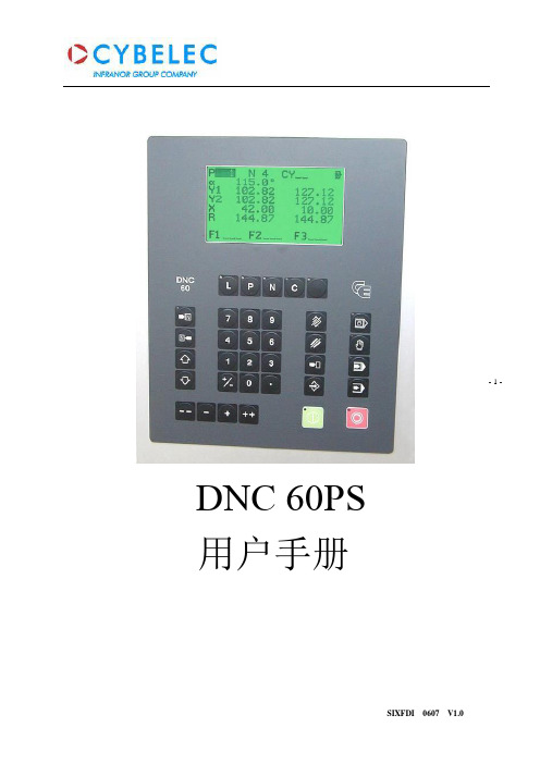
- 1 - DNC 60PS用户手册- 2 - 目录1 硬件介绍...................................................................................................................1 1.1 前面板....................................................................................................................1 2 按键功能...................................................................................................................2 2.1 屏幕页面选择键........................................................................................................2 2.2 工作模式选择键........................................................................................................2 2.3 指令键....................................................................................................................3 2.4 光标键....................................................................................................................4 2.5 “手动操作”键.......................................................................................................4 3 系统说明..................................................................................................................4 3.1 主菜单...................................................................................................................4 3.2 等级保护................................................................................................................5 4 模具编程..................................................................................................................6 4.1 查询上模目录..........................................................................................................6 4.2 查询下模目录..........................................................................................................7 4.3 上模/下模编制..........................................................................................................7 5 产品编程..................................................................................................................8 5.1 L-alpha 长度角度编程.............................................................................................8 5.2 N 页面直接编程. (16)5.3 产品校正...............................................................................................................19 6 产品目录管理...........................................................................................................20 6.1 调用产品...................................................................................................................20 6.2 删除产品...................................................................................................................20 7 参数模具备份和一键恢复功能......................................................................................20 7.1 Internal backup 内部备份......................................................................................21 7.2 Internal restore 内部恢复.......................................................................................21 8 系统报警信息说明 (22)- 3 -1 硬件介绍1.1 前面板下图为60系统的前面板,该前面板包括1块5.5英寸高对比度LCD 液晶显示器和编程及轴控制所需用到的各类按键.各按键功能将在下一章节详细介绍.按键面板包括以下按键: ·10个数字键(0-9) ·指令键·翻页与光标移动键 ·手动操作键·屏幕页面选择键(LED 灯显示按键状态) ·4种工作模式选择键(LED 灯显示按键状态) ·启动与停止键(LED 灯显示按键状态)液晶显示器 屏幕页面选择键 工作模式选择键 数字键 指令键 手动操作键 启动键 停止键- 4 - 2 按键功能2.1 屏幕页面选择键主菜单进入主菜单和EASY BEND(轻松折弯)页面。
DCS维护手册
DCS维护手册主要内容l.维护基础知识l.预防维护l.故障维护一、维护基础知识系统维护的意义l.必要性:系统中任一环节出现问题,均会导致系统部分功能失效或引发控制系统故障,严重时会导致生产停车。
l.系统维护——故障处理、保持系统的良好运行状态、优化系统系统使用维护的主要工作l.预防维护防患于未然,避免出现故障或出现影响生产的故障。
l.故障维护及时有效地发现和排除故障,保障正常生产。
树立正确的维护观念系统维护重在预防!用到哪些常用工具?l.硬件工具:l.仿真器l.过程校验仪、FLUKE、电子电位差计、电阻箱、信号发生器l.线缆测试l.除尘工具l.超声波清洗仪l.接地测试仪表二、预防维护.主要内容1.日常维护2.大修期间维护1、日常维护日常维护的主要内容:l.控制室维护管理l.控制站维护l.操作站维护l.网络维护控制室管理l.密封所有走线孔(坑);l.保证空调设备稳定运行,室温变化小于+5℃/h,避免凝露;l.现场与控制室合理隔离,防尘,定时清扫,保持清洁;l.通干净仪表空气使控制室保持正压,且室内外压差不应低于25Pal操作台内通入仪表风l尽量保持控制室密封设置两道门使用双层玻璃l使用胶泥封堵控制室电缆进出口l.制定严谨的控制室操作规程,减少人员出入。
l.进出控制室时做到快进快出,随手关门。
窗户密闭l.保持适当的湿度,40%~60%安放湿度检测仪,专人监测湿度过大-放置碱石灰,湿度过小-放置增湿器l.需考虑空调系统自身引入外部腐蚀性气体的问题控制室管理良好的标准l.完备的管理制度l.整洁的环境l.定期的检查和整改l.控制室及周边环境变动应经过严格审批控制站管理l.非维护人员不得擅进机柜室;l.保持柜内外的清洁;l.严禁擅自改装、拆装系统部件;l.不得无故拉动机笼接线、接地供电线及通信电缆;l.锁好柜门,专人保管钥匙;l.定时检查和维护;主控卡及数据转发卡切换l.正常生产过程中主控卡应尽量避免人工切换l.如需工作备用切换,应通过拔出一根工作主控卡的网线来实施l.拔出主控卡并插回后,必须等数据拷贝完成后才可拔另一块主控卡,否则在生产过程中会造成严重后果l.数据转发卡也尽量避免人工切换,如需切换,在拔出数据转发卡并插回后,必须等数据拷贝完成后才可拔另一块数据转发卡操作站硬件维护l.不带电插拔;l.保持清洁,防灰防水;l.严禁擅自改装、拆装机器;l.发现有硬件故障及时向厂家报修;操作站管理l.防止病毒侵入;l.严禁进行不必要的操作;l.做好驱动软件、组态软件的硬盘备份;l.做好组态的备份规范、组态修改记录管理规范;网络维护l.A网、B网不得相互交换;l.定期检查线缆连接的可靠性;l.定期检查各组件指示灯状态;l.定期从各个节点互相PING;l.观察动态数据是否正常显示和刷新;UPS系统维护UPS系统的使用与维护.1、UPS系统组成——UPS、电池.2、运行原理简介.3、电池的使用和维护电池是UPS系统中的重要组成部分,其好坏直接关系到UPS系统正常工作。
DSC-60软件更新指南说明书

Updating the DSC-60 SoftwareRefer to: “How to update system program”1) Remove the Top Cover and verify the switches on S3 are correct.2) Refer to the instructions for an IB581 or PC, depending on which unit will be used, toupdate the DSC-60.3) Update both the Main and Modem software.4) After programming cycle power and press the [3/Test] key.5) When the Test is done the alarm will sound.6) Press and hold the [1/RT] key, while pressing the [*/File] key 5 times.7) The software versions should now be: Main CPU 02.12Modem 01.04Refer to: “Resetting Memory-All Clear”1) Follow the “Resetting Memory-All Clear” procedure.Note: Refer to the photos of the Control/Modem PCB and Back panel during these Procedures.3. How to update system program 3. How to update system programThe program disk supplied includes two programs: main program and modem program. To update the system program, DIP switch #1 and #2 of S3 on the CONTROL/MODEM board must be set to ON position. Either of an IB-581 or a PC PC/A T compatible is connected as follows.Using IB-581Any IB-581 using for DP-6, Inmarsat-B and –C can be used.Using PCThe PC is connected to the DSC-60 as below.Connection between DSC-60 and PC/IB-581The connection is made with the following interconnection cable. The connector to the DSC-60 is a 25-pin D-SUB male, and to the IBN-581 or PC a 9-pin D-SUB female.D-SUB 9pin D-SUB 25pin3. How to update system program Refence)Refer er erence)The file size differs depending on the program revision level. The sizes listed here arereference only.File name SizeDSC60BIN689,056LOAD BIN15,304MODEM BIN29,129PROG TXT9UPDSC BA TY38UPMODEM BAT39UPPG EXE74,9603. How to update system program 3.1 Updating MAIN program with IB-5811. Connect the IB-581 to the DSC-60.2. Turn on the IB-581, but do not turn on the DSC-60.3. Terminate the terminal program.When using IB-581 for DP-6, FELCOM 12/81, while press and holding down [Alt] and[Fn], press [F2]. For example, A:\DP10\TERMINAL appears on the DP-6 terminal.When using IB-581 for FELCOM 11, press [F1] and [8] in order.4. Insert the program floppy disk in the slot.5. Type B: and press [Enter]. The prompt B:\> appears.6. Type “UPDSC” and press [Enter]. The following message appears.Program upload utility Version 6.21Copyright(c) FURUNO ELECTRIC CO., LTD.1997,1998,1999 (T.K)uppg infile 1 infile 2 p1 p2 p4 p5p1:Deletion waiting time.p2:Waiting time to write.p3:Password output interval.p4:ID number.(1,2...)p5:Poer number.(1,2...)Erase Wait:osecWait:oWait counter=100Port no.=1TARGET POWER ON.7. Turn on the DSC-60.The indication on the DSC screen changes as below. The picture on the IB-581 runs.8. Wait for about 5 minutes.9. The DOS prompt appears after the message “Finish version up.”10. Turn off the DSC-60, disconnect the IB-581 and turn on the DSC-60 again.11. Press [3/TEST/DEF] to perform the selftest and confirm the program has been updated.3. How to update system program 3.2 Updating MODEM program with IB-5811. Connect the IB-581 to the DSC-60.2. Turn on the IB-581, but do not turn on the DSC-60.3. Terminate the terminal program.When using IB-581 for DP-6, FELCOM 12/81, while press and holding down [Alt] and[Fn], press [F2]. For example, A:\DP10\TERMINAL appears on the DP-6 terminal.When using IB-581 for FELCOM 11, press [F1] and [8] in order.4. Insert the program floppy disk in the slot.5. Type B: and press [Enter]. The prompt B:\> appears.6. Type “UPMODEM” and press [Enter]. The following message appears.Program upload utility Version 6.21Copyright(c) FURUNO ELECTRIC CO., LTD.1997,1998,1999 (T.K)uppg infile 1 infile 2 p1 p2 p4 p5p1:Deletion waiting time.p2:Waiting time to write.p3:Password output interval.p4:ID number.(1,2...)p5:Poer number.(1,2...)Erase Wait:osecWait:oWait counter=100Port no.=1TARGET POWER ON.7. Turn on the DSC-60.The message “Now Loading” appears on the DSC screen. The picture on the IB-581 runs.8. Wait for about 5 minutes.9. The DOS prompt appears after the message “Finish version up.”10. Turn off the DSC-60, disconnect the IB-581 and turn on the DSC-60 again.11. Press [3/TEST/DEF] to perform the selftest and confirm the program has been updated.3. How to update system program3.3 Updating MAIN program with PC1. Connect the PC to the DSC-60.2. Turn on the PC, but do not turn on the DSC-60.3. Insert the program floppy disk in the slot.4. Type a: and press [Enter] to select drive A5. Type “UPDSC” and press [Enter]. The following message appears.Program upload utility Version 6.21Copyright(c) FURUNO ELECTRIC CO., LTD.1997,1998,1999 (T.K)uppg infile 1 infile 2 p1 p2 p4 p5p1:Deletion waiting time.p2:Waiting time to write.p3:Password output interval.p4:ID number.(1,2...)p5:Poer number.(1,2...)Erase Wait:osecWait:oWait counter=100Port no.=1TARGET POWER ON.6. Turn on the DSC-60.The indication on the DSC screen changes as below.Execute STEP1Execute STEP2xxxxxByte transferNow Erasingxxx percent completed7. Wait for about 5 minutes until the xxx percent reaches to 100.8. The DOS prompt appears after the message “Finish version up.”9. Turn off the DSC-60, disconnect the IB-581 and turn on the DSC-60 again.10. Press [3/TEST/DEF] to perform the selftest and confirm the program has been updated.3. How to update system program3.4 Updating MODEM program with PC1. Connect the PC to the DSC-60.2. Turn on the PC, but do not turn on the DSC-60.3. Insert the program floppy disk in the slot.4. Type a: and press [Enter] to select drive A.5. Type “UPMODEM” and press [Enter]. The following message appears.Program upload utility Version 6.21Copyright(c) FURUNO ELECTRIC CO., LTD.1997,1998,1999 (T.K)uppg infile 1 infile 2 p1 p2 p4 p5p1:Deletion waiting time.p2:Waiting time to write.p3:Password output interval.p4:ID number.(1,2...)p5:Poer number.(1,2...)Erase Wait:osecWait:oWait counter=100Port no.=1TARGET POWER ON.6. Turn on the DSC-60.The indication on the DSC screen changes as below.Execute STEP1Execute STEP2xxxxxByte transferNow Erasingxxx percent completed7. Wait for about 5 minutes until the xxx percent reaches to 100.8. The DOS prompt appears after the message “Finish version up.”9. Turn off the DSC-60, disconnect the IB-581 and turn on the DSC-60 again.10. Press [3/TEST/DEF] to perform the selftest and confirm the program has been updated.DSC-60Resetting Memory-All Clear1. Remove the top cover by removing the 4 side screws, and 1 screw from the rearpanel of the DSC-60.2. Connect power to the DSC-60.3. Turn on the unit and wait for the WATCH KEEPING screen to appear.4. Press the SETUP key. Use the arrow keys to select SYSTEM.Press the ENT key.5. Record the system settings, these will need to be reentered later.6. Press the CANCEL key to return to the WATCH KEEPING screen.7. Press the NMI switch located on the front right of the Control/Modem PCB(05P0702). Refer to the attached Control/Modem page.8. The unit will now display:9. Enter the password, 652111. As you enter the password, the unit will emit error tones.Ignore the error tones as you enter the password.10. Use the down arrow key to select ALL Clear. Press the ENT key.11. Enter the 9 digit MMSI number. Press the ENT key.DSC-60Resetting Memory-All Clear (Cont.)12. The display will now show PLEASE POWER OFF.Turn off the DSC-60 power.13. Turn the DSC-60 power back on.14. Now verify the System Settings and MMSI.15. Press the SETUP key. Use the arrow keys to select SYSTEM.Press the ENT key.16. Enter the password, 652111. As you enter the password, the unit will emit error tones.Ignore the error tones as you enter the password17. Renter the system settings recorded earlier.18. Turn the power off, put the top cover back on and reinstall the unit.2.3 CONTROL/MODEM(05P0702)(RS-232C/422)S2:DMC S3:NBDP S4:RTU21:PIO/SIOU4:F .ROM(MAIN)U6,7:SRAMU3:MAIN CPUU15:GATE ARRAY S 1: N M I S WU5:EEPROM U13:DSPC67U11:F .ROM(MODEM)U12:CODECC34(C.Loop/RS-422)S5(DMC) S8 S7 S6J1J2J3J4J5J6J7J8J9R152S4 [RT] S3 [NBDP]S2 [DMC]S6S7S8232422[CALL]DMCS4-S2: Selection of TX/RX data communication system of S4:RT“232” in case of MIF format“422” in case of IEC-6112 formatS3,S2:NBDP and DMC“232” in case of RS-232C “422” in case of RS-422S5: Selecting hardware of RX data (C.Loop/RS-422) S5-1 NBDP S5-2 RT S5-3 DMC S5-4 NMEAS6-S8: Selection of TX/RX data communication system of DMC2. PCBsS5[C.Loop]2.WIRING 2.1Wiring2.1.1Standard wiringAll external equipment are connected to appropriate connectors on the rear panel of the DSC-60. The figure below shows the location of these connectors. Note that all interconnection cables are optionally supplied. For further details, refer to the interconnection diagram at the end of this manual.DMC (current loop) or Distress Alert UnitReceiver AntennaPower 24 VDC TPower (24 VDC)Attach the connector (supplied) to the power cable and plug it into the 24 VDC connector at the rear of the main unit. When connecting to the optional AC-DC power supply unit PR-300, supply AC power and DC power to the PR-300. See paragraph “2.2 Connection of AC-DC Power Supply Unit PR-300” for detail.Ground ()Connect either a copper strap or 1.25 sq vinyl wire (local supply) between ship’s superstructure and ground terminal on the DSC-60.Note: Ground the equipment to prevent mutual interference.。
DSC操作指南
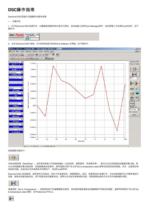
DSC操作指南Diamond DSC型差⽰扫描量热仪操作指南⼀、仪器开机1、打开Diamond DSC电源开关,仪器⾯板前⾯的RDY指⽰灯亮后,启动电脑上的的Pyris Manager软件,会在屏幕上⽅出现Pyris任务栏,如下图所⽰:2、点击“Diamond DSC”按钮,约10秒钟后就可启动Pyris Software 主界⾯。
如下图所⽰:控制⾯板功能如下:开始/结束按钮(Start/Stop)。
当所有的准备⼯作准备就绪后(⽐如加样、温度程序、热流稳定等),就可以点击该按钮启动数据采集过程。
再次点击则数据采集过程结束,实验数据被⾃动保存,程序温度以⽤户定义的“Go to temperature rates”速率⾃动回到加样温度。
另外,此按钮还有连线的功能。
当在DSC主机电源未开的情况下,启动Pyris软件和Diamond DSC 启动按钮,虽然软件已经启动,但处于未连接状态,按钮图案为。
此时,如果将DSC电源打开,点击该按钮就可以⽅便快速进⾏连接,按钮也恢复连接状态,⽽不⽤退出软件重新启动。
但再次点击却没有断线的功能,⽽是根据当前的⽅法⽂件开始数据的采集。
调温按钮(Go to Temperature)。
该按钮和其下的编辑框配合使⽤,⽬的是将程度温度⾛到编辑框中所指定的温度,速率同样是⽤户定义的“Go to temperature rates”速率,在“Preference”中定义。
回到加样温度(Go to Load)。
将程序温度调到加样温度。
加样温度在“Preference”中定义。
等温(Hold Temperature)。
不论仪器是在空闲状态还是数据采集状态,点击该按钮都将⽴即停⽌对程序温度的改变,也即开始在当前温度下的等温过程。
洗炉⼦(Clean Furnace)。
启动软件的“洗炉⼦”进程。
⽅法是将炉温升⾼到600℃保温⼀段时间。
⽤户可以通过再次电选该按钮随时终⽌洗炉⼦进程。
⾃动进样器控制(Autosampler Control)。
DSC操作规程范文
DSC操作规程范文一、引言数字选择通信(DSC)是一种国际海事通信标准,用于VHF和MF/HF频段的呼叫、紧急呼叫和广播通信。
DSC操作规程旨在规范和指导相关人员在DSC通信中的操作行为,确保通信的安全与有效性。
二、操作准备1.操作人员应熟悉DSC通信设备的使用方法,并确保设备处于正常工作状态。
2.在进行DSC通信前,操作人员应先进行预呼测试,确认设备的正常工作,并检查天线连接是否良好。
3.操作人员应保持和更新有关船舶的DSC通信设备的信息,包括船名、呼号、MMSI等。
三、DSC呼叫1.DSC呼叫应符合国际海事通信规定,按照相应频道的频率进行呼叫。
2.DSC呼叫前应先听取一段时间的频道,确保没有其他通信,避免互相干扰。
3.DSC呼叫时应选择适当的DSC呼叫类型,如一般呼叫、个体呼叫或广播呼叫,并正确填写相关的呼叫信息。
4.在进行DSC呼叫时,应保持语音通信频率的空闲,以便进行后续的语音通信。
四、DSC紧急呼叫1.在紧急情况下,操作人员应立即进行DSC紧急呼叫,并按照国际海事通信规定填写相关的呼叫信息。
2.紧急呼叫时应保持语音通信频率的空闲,以便进行后续的语音通信。
3.在紧急呼叫后,操作人员应尽快与相关救援机构进行语音通信,详细说明紧急情况并提供有关的信息。
五、DSC广播通信1.DSC广播通信应根据航行区域和航行计划进行选择,以接收并传播有关的航行警示和气象信息。
2.在收到DSC广播通信时,操作人员应及时进行相关的应答,并采取相应的措施。
3.在进行DSC广播通信时,应选择适当的广播频道和广播区域,并按照国际海事通信规定填写相关的广播信息。
4.每天结束前应对所收到的DSC广播通信进行总结和记录,以备后续参考。
六、操作注意事项1.DSC通信应遵守国家和国际通信规定,严禁进行非法呼叫和干扰通信行为。
2.在进行DSC通信时,应注意语音通信频率的空闲和使用正确的通信格式,确保通信的准确和清晰。
3.操作人员应保持良好的职业操守,不得泄露船舶的DSC通信信息,并妥善保管相关通信记录和文件。
福隆DSC-60手机号监控收音机用户操作指南说明书
Installation Manual DSC/WATCH RECEIVERDSC-60SAFETY INSTRUCTIONS .............................................................................i SYSTEM CONFIGURATION.........................................................................ii EQUIPMENT LISTS.....................................................................................iii 1. MOUNTING.. (1)1.1 Main Unit............................................................................................................................11.2 Antenna (option).................................................................................................................31.3 External Loudspeaker ........................................................................................................51.4 Handset Hanger (option)....................................................................................................51.5 AC-DC Power Supply Unit (option).....................................................................................51.6 Printer PP-510 (option).......................................................................................................61.7 Distress Alert Unit IC-302-DSC/Incoming Indicator IC-303-DSC. (6)2. WIRING (7)2.1 Wiring.................................................................................................................................72.2 Connection of AC-DC Power Supply Unit PR-300 (option) (11)3. INITIAL SETTINGS (13)3.1 System Setup...................................................................................................................133.2 Setting of DIP Switches....................................................................................................173.3 Preamp Setting (20)4. RX BOARD (OPTION)............................................................................21PACKING LISTS.......................................................................................A-1OUTLINE DRAWINGS..............................................................................D-1SCHEMATIC DIAGRAMS.........................................................................S-1The paper used in this manualis elemental chlorine free.9-52 Ashihara-cho,SYSTEM CONFIGURATION24 VDC100-115/200-220 VAC1φ, 50/60 HzNote: DISTRIBUTOR DB-120/DB-500 not necessarywhen using FS-5000 series radiotelephone.EQUIPMENT LISTSStandard SupplyName Type Code no.Qty RemarksMain Unit DSC-60-1Installation Materials CP05-07901005-950-180 1 setAccessories FP05-05200000-055-407 1 set FP05-05201, FP05-05202,LoudspeakerOptional EquipmentNameTypeCode no.QtyRemarksOP05-91005-950-34005P0703 boardRX Board Kit OP05-93005-950-610 1 set 05P0703 board, w/shield casesAC-DC Power Supply Unit PR-300000-130-4311PrinterPP-510- 1 setw/installation materials (CP16-01200), accessories (FP16-00100)Distress Message Controller DMC-5-Distress Alert Unit IC-302-DSC - 1 set w/Installation materials Incoming Indicator IC-303-DSC - 1 set w/Installation materials Whip Antenna 04S4176000-112-8451 2.6 meterPreamp Unit FAX-5000-075-016 1 set 05S0784*1m*000-123-58205S0784*3m*000-123-583Cable Assy05S0784*5m*000-123-5841For SSB radiotelephone, w/D-sub connectorsOP04-2*10m*000-041-174OP04-2*20m*000-041-175OP04-2*30m*000-041-176OP04-2*40m*000-041-177Extension Cable Kit OP04-2*50m*000-041-1781For extension of FAX-5 cableCO-SPEVV-SB-C 0.2X2P*5m*000-111-680CO-SPEVV-SB-C 0.2X2P*10m*000-120-792CO-SPEVV-SB-C 0.2X2P*15m*000-120-793CO-SPEVV-SB-C 0.2X2P*20m*000-120-794CO-SPEVV-SB-C 0.2X2P*30m*000-120-2141For navigator, DMC-5CO-SPEVV-SB-C 0.2X5P*5m*000-560-451CO-SPEVV-SB-C 0.2X5P *10m*000-560-452CO-SPEVV-SB-C 0.2X5P *15m*000-139-427CO-SPEVV-SB-C 0.2X5P *20m*000-103-868Twisted-pair CableCO-SPEVV-SB-C 0.2X5P *30m*000-103-8691For distress alert unit/received call unitHandset/bracket HSC701K-B20000-138-0001 set1. MOUNTINGUnit1.1 Main1.1.1 GeneralThe DSC-60 can be mounted on the overhead, on a tabletop, on a bulkhead, or flush mounted in a panel. Mount the unit where it can be easily viewed and operated. When selecting a mounting location, keep in mind the following considerations, in addition to those already mentioned.•Locate the unit away from water splash and rain.•The temperature and humidity of the location should be stable and moderate.•Keep the unit away from exhaust gas and heating and cooling vents.•Select a well ventilated location.•Select a location where shock and vibration are minimal.1.1.2 Compass safe distanceA magnetic compass will be affected if placed too close to the main unit. Keep the following compass safe distances in mind when selecting a mounting location.Standard compass:0.3 metersSteering compass:0.2 metersOverhead TabletopFlush Mount Bulkhead1.1.3 Mounting2581083065- 7.5190305100100150 3264545123Notes•All dimensions in millimeters.•For added support fasten unit to mounting location with nuts, bolts and washers instead of tapping screws.•Leave sufficient space at sides and rear of the unit for maintenance and service purposes.The minimum recommended space appears in the figure above.1.1.4Flush MountingThe hanger is mounted with the unit when the unit is flush mounted. Be sure the mounting location is strong enough to support the weight of the unit.Prepare cutout of 255 x 103 in panel.983897.5187.5(option)1.2 AntennaPerformance of this unit is directly related to the antenna installation. In general, the antenna should be installed as high as possible on the boat, free from the influence of nearby antennas, rigging and masts.The antenna commonly used for the DSC-60 is a 6 m whip antenna (local supply), long wire or optional whip of 2.6 m length with preamp unit (optional supply).The antenna input on this unit is automatically protected against strong induction by a protective circuit. For better performance, however, we recommended use of the preamp unit FAX-5.Antenna cable (option)Connect the antenna to the unit with any 50 ohm coaxial cable (RG-10U/Y or equivalent). Connect the center conductor of the coaxial cable using the junction box (type: AJB1-1A, code no.: 000-870-284, order from FURUNO).AJB1-1APreamp unit (option)The body of the preamp unit can be mounted two ways;1. The bottom of the preamp unit is designed to accept a threaded extension mast of 1 inchdiameter. The pitch of the thread should be 14 threads per inch. T o prevent undue flexing of the mast in heavy winds, the mast should not be longer than 5 feet (1.5 m).2. The side of the preamp unit has a molded channel so that it may be mounted directly to astub mast with two stainless steel hose clamps. Hose clamps must be arranged locally. Screw the 2.6 m whip antenna tightly onto the preamp unit and waterproof the junction and other exposed metallic parts with sealing compound (silicone rubber, putty, etc.).Note that a wire antenna of 2 to 3 meters length may be used instead of the whip antenna. Note: The preamp unit requires about 9 VDC power. See page 20.Thread(14 threads/inch)1" Pipe2.6 m Whip AntennaMastHose ClampCoupling NutAntenna Wire Wire Antenna FixturePreamp Unit50Earth1.3External LoudspeakerThe external loudspeaker sounds the alarm. It can be installed on a tabletop, the overhead or bulkhead. Fasten the loudspeaker to the mounting location with tapping screws, or nuts, bolts and washers. For mounting dimensions, see the outline drawing at the end of this manual.1.4Handset Hanger (option)The mounting location should provide easy access to front panel controls while operating the handset. Also, the length of the standard handset cable is 100 cm, so locate the handset hanger within 100 cm of the unit.1.5AC-DC Power Supply Unit (option)For Convention vessels, both AC and DC power must be fed to the DSC-60, via an AC-DC power supply unit. When AC input fails, DC power is supplied. FURUNO can supply the PR-300 AC-DC power supply unit.1.5.1Mounting considerationsWhen selecting a mounting location, keep in mind the following points.•Select a location which provides adequate ventilation.•The location must be clean and dry.•The mounting location must be able to support the weight of the unit (14.5 kg) under the continued conditions of vibration normally encountered aboard the vessel. If necessary,reinforce the mounting location.•The PR-300 will affect a magnetic compass if it is placed too near the compass. Observe the following compass safe distance to prevent deviation of a magnetic compass;Standard compass:0.9 metersSteering compass:0.7 meters1.5.2MountingRefer to outline drawing at the end of this manual.1.6Printer PP-510 (option)Install the unit with the two mounting fixtures (supplied). Refer to the outline drawing at the end of this manual. Connect the interconnection cable between the printer and the DSC-60.For how to load paper and set ribbon cassette, refer to the Operator’s Manual of the printer. Mounting1. Select a flat surface. (Compass safe distance, Standard, 1.0 meters, Steering, 0.8 meters)2. Fix the printer to the mounting location with two mounting fixture.1.7 Distress Alert Unit IC-302-DSC,Incoming Indicator IC-303-DSCSelect the mounting location where the button on the unit can be operated easily in an emergency. See the back of the manual for mounting dimensions and recommended clearance space. (Compass safety distance: Standard, 0.8 m, Steering, 0.6 m)Unfasten four screws to remove the cover.1.2. Fasten IC-302 with four tapping screws to remove the cover.3. Pass the cable through appropriate entrance to connect to the terminal board.There are two cable entrances, one at the bottom and on the back. Select one.4. Attach the cover with four screws.2.WIRING 2.1Wiring2.1.1Standard wiringAll external equipment are connected to appropriate connectors on the rear panel of the DSC-60. The figure below shows the location of these connectors. Note that all interconnection cables are optionally supplied. For further details, refer to the interconnection diagram at the end of this manual.DMC (current loop) or Distress Alert UnitReceiver AntennaPower 24 VDC TPower (24 VDC)Attach the connector (supplied) to the power cable and plug it into the 24 VDC connector at the rear of the main unit. When connecting to the optional AC-DC power supply unit PR-300, supply AC power and DC power to the PR-300. See paragraph “2.2 Connection of AC-DC Power Supply Unit PR-300” for detail.Ground ()Connect either a copper strap or 1.25 sq vinyl wire (local supply) between ship’s superstructure and ground terminal on the DSC-60.Note: Ground the equipment to prevent mutual interference.D.ANT (Distress & Safety Watch Keeping Receiver Antenna)The DSC antenna is connected to the main unit with a 50 ohm coaxial cable, type RG-8/8U or equivalent. Attach an M-type plug (if necessary) to the cable as shown below. Screw the plug into the D. ANT connector at the rear of the main unit.ANT (optional Rx Board kit is required)The antenna is connected to the main unit with a 50 ohm coaxial cable, type RG-8/U or equivalent. Be sure to leave some slack in the cable for future service and maintenance.Lay the coaxial cable and attach an M-type plug (if necessary) to the cable as follows.1. Remove the sheath by 30 mm.2. Bare 23 mm of the center conductor. Trim braided shield by 5 mm and tin.3. Slide coupling ring onto cable.4. Screw the plug assembly on the cable.5. Solder plug assembly to braided shield through solder holes. Solder contact sleeve toconductor.6. Screw coupling ring into plug assembly.7.Screw the plug into the ANT connector at the rear of the main unit.Solder here.sides of hole.SPConnects the loudspeaker MX910-X01 (supplied with the accessories) here.2.1.2External EquipmentIEC61162-1 (NMEA)Connects a navigator here. The DSC-60 can receive the following sentences in IEC-61162-1format. Use the FM14-5P connector (supplied) and interconnection cable type CO-SPEVV-SB-C 0.2x2P (option). For how to fabricate the cable, see the figure in below.• GLL: Latitude and longitude• RMC: Generic navigation information • RMA: Loran C data (L/L, LOPs, etc.)• GGA: GPA position, UTC •ZDA: UTC, day, month, and yearPriority: GGA>RMC>RMA>GLL>ZDAPriority is kept for one minute.DMCConnects the DMC Terminal DMC-5 or Distress Alert Unit IC-302 here using the appropriate cable and connector. For the fabrication, see the figure in below.• DMC-5: CO-SPEVV-SB-0.2X2P cable (option) and FM14-6P connector (supplied).•IC-302: CO-SPEVV-SB-0.2X5P cable (option) and FM14-6P connector (supplied)RCV. BZConnects the indicator IC-303 here. Use the FM14-7P connector (supplied) and CO-SPEVV-SB-C 0.2X5P cable (option). For how to fabricate the cable, see the figure in below.Twist and trim the shield.Vinyl tapeRemove the outer sheath and armor by 45 mm.Remove the inner sheath by 14 mm,and the sheath of the cores by 3 mm.Cut the unused cores.Solder a vinyl wire to the sheild.Vinyl wireSolder the cores to the connector,and tape the sheath.Fabrication of CO-SPEVV-SB-C for IEC61162-1, DMC and RCV. BZ terminalsPRINTERConnects the printer PP-510 (option).HANDSETConnects the HSC701K-B20 handset (option).RTConnects the SSB radiotelephone, by using the cable assembly 05S0784 (option).For the cable assembly UL2464-SB(M) (local supply, with no connector), fabricate the connector 17JE-23250-02 (DSC, supplied as installation materials) as below.Fold back the shield, and thenwind the metallic shield tapeCable ClampCableType: UL2464-SB(M)Code no.: 000-125-302Note: For this cable fabrication;FS-1562/2550: Connector supplied as installation material is not used.FS-5000 series: Cut one side of the cable, and connect to the terminal board in the equipment.2.2Connection of AC-DC Power Supply UnitPR-300 (option)When connecting to an AC and DC ship’s mains, the optional AC-DC power supply unit PR-300 is required. Attach the crimp-on lug FV5.5-S4 (local supply) to the power cable (local supply) for connection with the PR-300. Use the power cable as below.•For AC power:DPYC-1.25 (Japan Industrial Standard) or equivalent•For DC power:DPYC-2.0 (Japan Industrial Standard) or equivalentSheathPaintS =1.25 mm=1.35 mm2(DPYC-1.25)S = 2.0 mm=1.8 mm2(DPYC-2) DPYC, sectional view2.2.1Changing tap connectionsThe transformer tap for input voltage has been st to 220 VAC (fuse 5A) at the factory.If necessary, change the transformer taps setting according to ship’s mains.100VAC SHIP'S MAINS110VAC SHIP'S MAINS200VAC SHIP'S MAINS220VAC SHIP'S MAINSTap connections in the PR-3002.2.2 Changing the power fuseChange the power fuse according to AC input voltage as follows.AC ship’s mains Fuse100/110 VAC10 A200/220 VAC 5 AFuse for AC ship's mainsAC-DC power supply unit PR-300, rear view2.2.3 GroundingConnect a ground wire between ship’s superstructure and a fixing screw on the PR-300.3.INITIAL SETTINGWhen turning on the power for the first time, the following items should be set on the System setup or Alarm setup menus.•Own ship’s ID•Watch receiver frequency band•Line out level for DSC signal•Transmission key timing•Remote control protocol for RT (Radiotelephone) port•Remote station function•Remote control for NBDP port•Detecting DSC signal strengthSetup3.1 SystemThe system setting is necessary after the installation. To prevent accidental transmission of the distress alert, remove the connector of SSB radiotelephone except when the sailing. This setting should be entered by a qualified technician. Under no circumstances shall the operator enter ship’s ID.3.1.1Opening the System Setup menu1. Press [SETUP] key to display the Setup menu.Setup menu2. Select “SYSTEM” with the cursor pad.3. Press the [ENT] key to display the System setup menu.4.Enter a password referring to the FURUNO INFORMATION.<Page 1> <Page 2>System setup menu3.1.2Watch receiver frequency bandSet the watch receiver as below.1. Open the System setup menu.2. Press or to select “WATCH RCVR”.3. Press the [ENT] key to display the WATCH RCVR pop-up window as below.WATCH RCVR pop-up window4. Pressor to select “MF/HF” or “MF” as appropriate.MF/HF: Maximum six distress/safety frequencies are available. (A1, A2, A3 and A4 area)MF: Distress/safety frequency is 2187.5 kHz only (A1 and A2 area)5. Press the [ENT] key.3.1.3Line out level for DSC signal settingSet line out level. For FURUNO SSB (600 Ω), set 0 dBm.1.Open the System Setup menu.2.Press or to select “LINE OUT”.3. Press the [ENT] key to display the pop-up window for adjustment of line out level.LINE OUT LEVEL pop-up window4. Press or to adjust the indicator bar (1.5 dBm step).5. Press the [ENT] key.3.1.4Transmission key timing settingSelect transmission timing, that is, the delay time in seconds to allow for tuning of transmitter before message is transmitted. (When connecting to other makes of SSB, set according to specifications of equipment.)1. Open the System setup menu.2. Press ! or " to select “TX-KEY TIMING”.3. Press the [ENT] key to display the pop-up menu for adjustment of transmission timing.TX-KEY TIMING pop-up window4. Press # or $ to adjust the indicator bar (AUTO, 0.1, 0.5, 1, 2, 3, 4, 5, 10, 15).FURUNO’s SSB: Set to AUTO (Timing is controlled by the MIF command <TU>.)Other makes of SSB: Set according to specifications of equipment.5. Press the [ENT] key.3.1.5Remote control protocol for RT (Radiotelephone) Port Select the protocol depending on the SSB radiotelephone connected.1. Open the System setup menu.2. Press ! or " to select “RT PORT”.3. Press the [ENT] key to display the RT PORT pop-up window.4. Press ! or " to select the appropriate setting.MIF:When connecting a FURUNO SSB radiotelephone (ex. FS-1562, FS-5000/8000).IEC:When connecting another maker’s SSB radiotelephone having IEC-61162-1 format.OFF: When connecting the radiotelephone having protocols except MIF/IEC, or not having remote control function.5. Press the [ENT] key.Note: When connecting with FS-1562/2550, set the system setting for remote operation on radiotelephone.3.1.6Remote station functionThis equipment can function as a SSB radiotelephone remote station as following procedure.1. Open the System setup menu.2. Press or to select “REMOTE STATION”.3. Press the [ENT] key to display the REMOTE STATION pop-up window.REMOTE STATION pop-up menu4. Press or to select the appropriate setting.ON: Function as remote station. ([RT/2182] key is available.)OFF: Not function as remote station.5. Press the [ENT] key.3.1.7Remote control for NBDP PortSelect ON or OFF depending on whether NBDP terminal is connected or not.1. Open the System setup menu.2. Press or to select “NBDP PORT”.3. Press the [ENT] key to display the NBDP PORT pop-up window.NBDP PORT pop-up window4.Press or to select the appropriate setting.OFF: Connecting with other maker’s NBDP or no NBDP.ON: FURUNO’s NBDP (ex. DP-6).4. Press the [ENT] key.3.1.8DSC signal strengthCH DET S LEVEL judges whether the DSC frequency to use to send a DSC message (Routine and Business only) is in use or not. The DSC message is not transmitted when the signal strength on the DSC frequency is higher than that set here. When the DSC frequency becomes clear, the DSC message is automatically transmitted. The setting range is OFF - 250 and the default setting is 100.1. Open the System setup menu.2. Press or to select “CH DET S LEVEL”.3. Press the [ENT] key to display the CH DET S LEVEL pop-up window.CH DET S LEVEL pop-up window4. Press or to adjust the indicator bar. T oo low a setting stops transmission of a DSCmessage because it detects noise on the DSC frequency. Alternately, too high a setting transmits the DSC message though low signal level is present on the DSC frequency used.5. Press the [ENT] key.3.2Setting of DIP SwitchesWhen the following equipment are connected, set the DIP switches in the main unit to select Current Loop, RS-232C or RS-422.•SSB radiotelephone•NBDP terminal•DMC terminal•NavigatorS6S7S8S6S7S8S2S3S4(RT)(NBDP)(DMC)232CALL (Except IC-302)3.2.1 Setting for SSB radiotelephone and NBDP terminalconnectionConnection with FS-1562 and DP-6, exampleConnection with FS-5000 and DP-6, exampleTx/Rx control data of FURUNO’s SSB radiotelephone is MIF protocol, RS-232C format.For SSB radiotelephone (RT)DIP switch S4#1#2#3#4ON ON OFF OFF(Setting for RS-232C setting)For NBDP terminalDIP switch S3#1#2#3#4ON ON OFF OFF(Setting for RS-232C)Note 1:When not connecting to NBDP terminal, set 1 and 2 to ON, 3 and 4 to OFF of S3, select OFF at the NBDP on the system setting menu.Note 2:When the distance between the DSC-60 and radiotelephone is 5 m or more use the current loop specification. To do this, set 1/2 and 3/4 of DIP switch S4 to OFF and ON, 2 of DIP switch S5 to C. Loop respectively. Also, set up the radiotelephone for current loop specification.3.2.2For other transceiver connectionWhen connecting to the transceiver which cannot be controlled by IEC-61162 format, select OFF at RT PORT on the setup menu.When connecting to other maker’s transceiver which is controlled by IEC-61162 format, set the DIP switches in the main unit.For SSB radiotelephone (RT), TX dataDIP switch S4#1#2#3#4OFF OFF ON ON(Setting for RS-422)For SSB radiotelephone (RT), RX dataDIP switch S5#2 is ON Setting for RS-422#2 is OFF Setting for Current Loop3.2.3For navigator connectionDSC-60[IEC]Navigator NAV DA T A(GLL,RMC,RMA,GGA,ZDA)Navigator connectionSet the output data format from the navigator to IEC: RS-422 or Current Loop, and set S5 DIP switch in the main unit as below.For IEC: RS-422DIP switch S5#4ONFor Current LoopDIP switch S5#4OFF3.2.4Connection to DMC-5, IC-302-DSCThe above equipment can be connected at DMC port at the back of the main unit. When connecting to them, set DIP switches as below.DMCSet to RS-422 as follows.S2S5S6S7S8#1#2#3#4#3#1#2#3#4#1#2#3#4#1#2#3#4OFF OFF ON ON OFF ON ON ON ON OFF OFF OFF OFF OFF OFF OFFOFFIC-302-DSCSet to Current Loop for IC-302 connection.S6S7S8All All AllOFF OFF ON3.3 PreampSettingWhen using the preamp for the watch receiver antenna, set J3 on the RX Board to ACTIVE.4. RX BOARD (OPTION)The RX Board 05P0703 (option) enables reception of routine DSC frequencies without the SSB radiotelephone connection. For complete modification, the whip antenna for routine DSC frequency is necessary.• Necessary Parts :RX Board Kit, Type :OP05-91, Code No. :005-950-340:RX Board Kit, Type :OP05-93, Code No. :005-950-610 (with shield case)No.RemarksQtyCodeName TypeRX Board 05P0703 005-950-530 1Connector assembly PH16DK-180 000-142-865 1Pan head screws M3X8 000-881-404 6Shield case RX-1 05-085-1051 100-285-160 1 OP05-93 onlyShield case RX-2 05-085-1052 100-285-170 1 OP05-93 onlyPan head screws M3X8 000-881-404 13 OP05-93 onlyThe unit functions normally without the shield case, however its use is recommended when noise might be a problem.Mounting1. Unfasten ten binding screws to remove the upper and lower covers from the main unit.2. For mounting the OP05-93, remove RX Board for distress frequencies.3. For mounting OP05-93, set the shield case RX-1 inside the main unit as shown below.Set fixing holes in shield case RX-1 to “pegs” in main unit.4. Fasten the optional RX Board 05P0703 inside the main unit with six pan head screws (M3X8,supplied). For mounting OP05-93, fasten the RX Board with shield case RX-1 with sixscrews.5. Attach the coaxial cable (from the rear panel) to J1 on the RX Board. For mounting OP05-93,attach the coaxial cable to J1 through the square bush of shield case RX-2.6. Connect the PH16PDK-180 connector assembly (supplied) between J2 on the RX Boardand J7 on the CONTROL/MODEM Board.Pass the PH16DK-180 connectorassembly through this hole.Coaxial cable16P connector assy;From J2 on theRX Board (option)Note:When using the preamp unit (option), change jumper plug position on J3 to “ACTIVE” on the RX Board to supply power to the preamp unit. For detail, see “3.3 Preamp Setting”on page 20.7. For mounting OP05-93, fasten the shield case RX-2 inside the main unit with thirteen panhead screws.Be careful not to pinch 16P connector assembly by the shield cover RX-2.8. For mounting OP05-93, refasten the RX Board for distress frequencies with six pan headscrews.9. Reassemble the main unit.。
系统操作维护手册范文
GH-600S酒店客房智能管理控制系统操作维护手册XXXX酒店赤峰市声光科技有限公司二○○九年目录一、系统概述.......................................................................................................................... 错误!未定义书签。
二、系统设备安装.................................................................................................................. 错误!未定义书签。
三、系统设备接线.................................................................................................................. 错误!未定义书签。
一、系统概述GH-600S酒店客房智能管理控制系统,是利用计算机控制、通讯、网络等技术,基于客房内的RCU(客房智能控制器)构成专用的网络,对酒店客房的安防系统、门禁系统、中央空调系统、智能灯光系统、服务系统等进行智能化管理与控制,实时监测客房状态、宾客需求、服务状况以及设备情况等,协助酒店对客房设备及内部资源进行实时控制分析的综合服务管理控制系统。
系统采用模块化设计,具有节能、增效、为客人提供人性化服务、提升酒店管理水平和酒店形象等诸多优势。
由于其功能丰富,兼容性强,并支持与其它系统接口,已成为酒店全面智能化的必不可少的一部分。
一个完整的GH-600S系统由以下三部分构成:1、单客房系统(以RCU为核心,可独立运行),见图一;2、通讯系统(可由RS-485&TCP/IP和TCP/IP以太网二种网络供选择),见图二;3、系统软件(运行于C/S结构的网络系统软件)。
DSC操作规程
DSC操作规程DSC操作规程(包括DSC使用原则、装备准备、操作步骤等),以下是一份完整版的规程,超过1200字。
一、DSC使用原则1.DSC使用是为了确保通信的有效性和安全性,应按照国家相关法规和通信礼仪进行操作,绝不得滥用DSC进行虚假报警或传播虚假信息。
2.DSC操作人员应具备相关通信技能和知识,熟悉DSC设备的操作和功能,并持有有效的通信操作证书。
3.DSC操作应遵循以下原则:准确性、迅速性、简洁性、尊重他人和机构。
4.DSC设备应按照规定进行定期维护和检验,确保其正常工作。
二、装备准备1.操作人员应事先熟悉所使用的DSC设备的品牌、型号和功能,并确保设备处于正常工作状态。
2.确保设备的电源充足,如有需要,应随时准备备用电池或电源适配器。
3.确保设备的天线连接良好,没有任何杂音或干扰。
4.将设备放置在平稳的表面上,确保操作方便且不会滑动。
三、操作步骤1.打开DSC设备,等待设备启动完毕。
2.在设备界面上选择相应的操作模式(如呼叫、信息发送等)。
4.在输入框中填写要发送的信息内容,确保简洁明了。
5.确认输入无误后,点击发送按钮,等待对方的回复或响应。
6.如有需要,操作人员可以根据DSC设备的功能选择适当的操作选项,如呼叫特定频道、发送警报等。
7.操作完成后,及时关闭设备并做好相应的记录。
四、常见问题和应对方法1.无法开机或设备出现故障:检查设备的电源和连接是否正常,如有需要,更换电池或修理设备。
3.收到无关信息或骚扰信息:根据设备功能屏蔽或删除相关信息,并采取必要措施防止再次受到类似信息。
4.需要紧急报警或求助:根据设备功能选择相应的警报选项,并及时向相关机构报告和求助。
五、操作注意事项1.严禁使用DSC设备进行虚假报警或传播虚假信息,如有违反者,将依法追究其法律责任。
2.在操作DSC设备时应注意周围的通信环境,确保不会对其他通信系统造成干扰。
3.严禁擅自更改设备的设置或参数,如有需要,应在相关人员指导下进行操作。
- 1、下载文档前请自行甄别文档内容的完整性,平台不提供额外的编辑、内容补充、找答案等附加服务。
- 2、"仅部分预览"的文档,不可在线预览部分如存在完整性等问题,可反馈申请退款(可完整预览的文档不适用该条件!)。
- 3、如文档侵犯您的权益,请联系客服反馈,我们会尽快为您处理(人工客服工作时间:9:00-18:30)。
MF/HF DSC设备操作手册(Model: DSC-60)渤海石油通讯网络公司编制控制面板,LED描述◆控制面板菜单说明:按键及指示灯功能Power 开关电源DISTRESS 按下并持续3秒钟以上就可以发送遇险警告。
刚开始按下时闪烁,按住超过3秒钟以后常亮。
在船收到遇险确认信息前此灯一直常亮。
按此键的时间少于3秒钟,DSC-60不会发出遇险警告。
CALL 除遇险警告外的呼叫Cursor Pad 选择菜单;调整音量大小。
(遇险或紧急告警以最大音量接收,不受扬声器控制。
)ENT 记录按键的输入CANCEL ●取消错误数据●返回上一级菜单●返回到DSC待机屏幕●关闭告警音●取消发射,打印●消除错错误信息1/RT/2182 ●从DSC待机屏幕转到无线电话的设置屏幕●在无线电话设置界面下,按下此键持续2秒以上转到2182.0kHz/J3E2/DSC 从无线电话的设置屏幕转到DSC待机屏幕3/TEST 每日检测4/IntCom 开关与无线电话间的通讯5/ACK 切换手动/自动确认功能6/SCAN 开始/停止在DSC待机界面下对DSC常规频率的扫描。
7/ ●扬声器开关●关闭蜂鸣器注意此键不能关闭遇险或紧急告警8/PRINT 打印通讯日志文件,当前屏幕(除DSC待机屏幕和无线电话设置屏幕外)和测试结果9/调节键盘/LCD背景屏幕亮度和对比度*/FILE ●在DSC待机界面下打开发送的消息文件以便发送●当准备一个0/LOG 在DSC待机界面下打开TX/RX日志文件#/SETUP 在DSC待机界面下打开设置菜单ALARM灯●遇险或紧急呼叫时以红色闪烁●安全或常规呼叫时以绿色闪烁(更快)OVEN 灯电源打开时点亮DISTRESS CALL PROCEDURE(遇险呼叫方法)当船舶上的生命遇到危险的时候,请按照下面的流程操作:1.掀开DISTRESS 按钮的盖板,按住[DISTRESS]按钮至少3秒钟显示下面的信息后,松开[DISTRESS]按钮。
2.遇险呼叫发射后会出现下面的显示。
3.按[CANCEL]键,取消报警的警报声。
4.通过无线电台和陆地站联系的流程如下:a)说三次MAYDAY.b)说出你的船舶名称和呼号三次。
“T his is ………”c)提供出遇险的种类和需要求助的方法。
d)描述你的船舶(船舶类型,人数,等等)以及任何有助于别人援助的信息。
注意:(详细操作方法请参考下面第3节内容)OPERATIONAL OVERVIEW(操作概述)1.Turning the Power On/Off (开/关主机)按住在您右手边的[POWER]按钮,将主机电源打开或关闭。
电源打开后,DSC 的标准屏幕就会出现。
2.DSC Standby Screen, Radiotelephone Setting Screen and Their Indications(屏幕菜单显示及功能设置)2.1DSC Standby Screen按[2/DSC]键显示DSC的标准屏幕,在这个屏幕下你可以进行所有呼叫的操作。
2.2Radiotelephone setting screen(无线电台设置屏幕)按[1/RT/2182]键显示无线电台的设置屏幕。
在这个屏幕下您可以进行无线电台的相关设置。
注意:在无线电台发射的时候“TX”会特别显示出来。
2.3Panel Backlighting, LCD Contrast and Brightnessa) 在DSC标准屏幕或无线电台设置屏幕下,按[9/]键。
出现下面的显示信息。
b) 使用▲键增加面板的背景亮度,LCD的亮度;▼键降低亮度。
当前背景亮度的设置使用数字和模拟两种方式来表示。
c) 使用左箭头键降低LCD的灰度;右箭头键提高LCD灰度。
当前灰度的设置使用数字和模拟两种方式来表示。
d) 按压[ENTER]键确认后返回前面正在使用的屏幕。
2.4Loudspeaker, Buzzer On/Off(扬声器,蜂鸣器的开/关)1.在DSC 标准屏幕或无线电台设置屏幕显示下。
2.在日常的报文信息来往状态下,按[7/ ]键打开或关闭扬声器和报警声音。
每次按这个键的时候,报文信息SOUND: ON or SOUND: OFF都会出现在屏幕上。
当扬声器被关闭的时候DSC标准屏幕和无线电台设置屏幕的右下方会显示OFF信息。
3.当扬声器打开的时候,按左箭头键降低音量;右箭头键增加音量。
设置范围时从0到63。
音量设置的显示是使用条形图表和数字方式显示在屏幕底部。
注意:无论什么时候开机,扬声器处于ON位置时,音量的设置都是在5的位置。
2.5Starting, Stopping Scanning DSC Routine Frequencies(DSC日常工作频率的启动,停止扫描)在DSC标准屏幕下,按[6/SCAN]键开始或停止扫描DSC日常工作频率。
DSC 常规频率可以通过菜单来进行选择。
注意的是DSC遇险频率是不能停止扫描的。
注意:当你使用的是可选的接收板(对于只接收DSC日常工作频率的接收板),以及当你关闭了频率发送器接收遇险信号的时候,DSC的日常工作频率是不能被接收到的。
2.6Automatic Acknowledge On/Off(自动应答功能的开/关)自动应答功能的特性在于当接收到单独呼叫,寻址呼叫,轮寻呼叫的时候(对于寻址和轮寻呼叫,需要在AUTO ACK菜单上分别将其设置在Enable位置上),其会自动发送应答码(ACK BQ)信号到频率发送器上。
在DSC标准屏幕上通过按[5/ACK]键来打开或关闭自动应答的功能。
每按一次这个键,AUTO ACK 或MANUAL ACK信息会出现在DSC标准屏幕的右上角。
注意1: 若想在本船正在通信的同时,得到优先级,需选择MANUAL ACK方式。
注意2: 在下列条件下自动应答功能是不能实现的:优先级:遇险,紧急或安全通讯种类:莫尔斯电报,传真,数据,无信息通讯频率:无信息OFF HOOK(拿起话筒状态)2.7Intercom On/Off(内通功能的使用)内通功能是指在当内部的DSC-60与SSB无线电台连接在一起时,它们之间可进行话音通讯的功能。
1.显示无线电台设置屏幕。
2.拿起话筒( Off Hook the Handset)3.按[4/IntCom]键。
就可以开始和SSB单边带进行对话了。
4.当完成通话,要挂上话筒关闭内通功能。
当内通功能关闭时,无线电台的设置屏幕上就不会在显示INTERCOM了。
5.注意:如果你是被其他船上的SSB无线电台呼叫,就会有“BEEP”的蜂音。
拿起话筒就可以进行通话了。
2.8Selection of On-screen Items(菜单目录的选择方法)通过选择On-screen上的目录来进行菜单和呼叫的工作。
下面的例子显示出了如何选择目录以及报警菜单下进行可选选择。
1.按[#SETUP]键进入设置菜单。
2.使用光标键选择菜单然后按[ENT],例如选择Alarm Menu.3.使用▲或▼选择需要的菜单目录后按[ENT]键。
例如,选择RCVD CALL。
就会在主菜单上出现下面的窗口。
4.使用▲或▼选择需要的内容。
5.按[ENT]键确认所选内容,按[CANEL]键两次返回DSC标准屏幕。
2.9Manual Entry of Position and Time(人工输入船位及时间)如果没有EPFS(电子定位系统)连接到DSC-60上或者EPFS连接错误,就需要人工输入船位和时间,如下方法所示:1.在DSC标准屏幕上,按[# SETUP]键显示设置菜单。
2.选择POSITION 并按[ENT]键进入位置菜单。
3.按[ENT]键打开INPUT TYPE 菜单。
注意1:如果选择的是ATUO,来自导航议的输入信号中断后就会出现“EPFS error!”的提示信息。
出现这样的情况,请检查导航仪。
注意2:如果选择的是MANUAL,提示信息“Update position”就会不断的出现,询问你是否需要更改位置信息。
4.按▼箭头键选择MANUAL 并按[ENT]键。
5.按[ENT]键后出现了纬度输入窗口。
6.输入四位数的纬度位置然后按[ENT]键。
7.按[ENT]键后打开了经度的输入窗口。
8.输入五位经度数字后按[ENT]键确认。
9.按[ENT]键后打开时间输入窗口。
10. 输入UTC时间后按[ENT]键。
出现设置菜单。
2.10Remote Control of FURNO SSB Radiotelephone( 单边带电台的控制) FURUNO SSB单边带电台部分的设置可以从无线电台设置屏幕进行控制,可以通过按[1/RT/2182]键进入单边带部分的设置。
你可以通过输入规定好的信道来输入需要的频率,或者直接输入RX和TX频率。
话筒既可以拿起也可以挂在座内。
需要注意的是:将SSB无线电台设置到2182Khz/J3E时,按[1/RT/2182]键至少要超过2秒钟的时间。
Mode Selection1.按[1/RT/2182]键显示无线电台设置屏幕。
2.用光标来选择MODE区,按[ENT]键。
3.确认所选的模式后按[ENT]键。
Channel selection当模式处于FAX状态时无法进行信道的选择。
1.选择CH区按[ENT]键。
2.信道可以直接使用数字键来输入,或者使用光标键。
By numeric keys使用数字键直接输入波段和信道然后按[ENT]键。
By Cursor Pada)按左箭头键将光标移动到波段的输入区域内。
b)使用上箭头键或下箭头键设置波段。
波段的显示顺序如下:c)按右箭头键。
d)使用上箭头键或下箭头键设置信道。
e)按[ENT]键。
信道被输入后出现TX和RX频率。
TX/RX Frequency Selection选择TX 或RX区后按[ENT]键。
用数字输入需要的频率。
按[ENT]键完成。
注意:如果你输入TX频率,那么RX也是同样的输入方法。
Power selection使用光标来选择功率,按[ENT]键确认,选择需要的功率后按[ENT]键。
注意:有些FURUNO SSB不提供HIGH,MID,LOW功率的选择。
Turing使用光标来选择调协,按[ENT]键确认,选择调协后,调协会自动执行,显示结果为:TUNE OK或者TUNE: NG ( No good)3.1 Sending Distress Alert(发送遇险警报)3.1.1 Sending distress alert by DISTRESS button(用DISTRESS发送遇险警报)安装了GMDSS系统的船舶,其DSC设备是用于船舶在发生人员生命收到危险时发送遇险警报的一种终端设备。
陆地站在接收到该遇险警报时会向遇险船只发送遇险信息应答。