FARO操作手册
FAROARM快速入门操作指南说明书
1.4 在安装设备及被测件时,应考虑到在测量范围内探针能 到达的区域。
1.5 测量时,探针不能超出规定的测量范围,以保证各关节 处于自由状态,否则不能保证测量精度,同时可能损坏 设备。
2、测量准确度
不正确的探针位置
测量准确度以两种方式表示:单点鉴定精度;空间长度最大误差 。
2.1 单点鉴定精度(Max-Min)/2(2δ)
2.2.4 定期鉴定
应定期对设备进行单点精度鉴定及空间长度误差校准,检查各关节的机械精度、测 量臂、探针等是否处于稳定状态,保证测量结果的准确、可靠。 注: ➢ 在校准过程中应保证环境温度符合要求(20±0.5℃)。 ➢ 只有在符合“单点精度”及“空间长度最大误差”要求下,才能保证测量结果准确、可 靠。 ➢ 上述校准方法的依据:国际三坐标通用标准 B89.4.22 标准。
第一部分 FARO Arm 综述
2.2 空间长度最大误差
是指测量臂在测量范围内空间任意方向长度的最大误差。
2.2.1 要求:≤±0.036 mm
对于FaroArm,一般来说,单点精度如果符合要求,那么长度最大误差也应该符 合要求。
2.2.3 校准方法 将标准器(量块)置于测量范围内的各个位置和方向上进行长度测量。
关节应力超限警告
编码器应力超限警告
第三部分 安装 FARO Arm
3、设备诊断
从测量菜单中,点击“设备” →“CMM” → “诊断”,弹出“诊断”对话框:
➢ 位置: 探针球心坐标值(相对设备坐标); ➢ 连接角: 6个编码器的读数,点击“创建报告”,
根据提示操作,创建编码器检测报告;
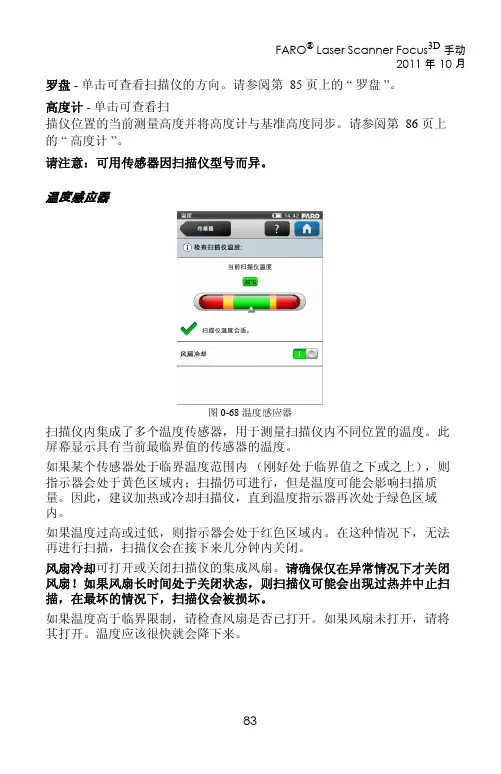
➢ 温度: 检查当前温度是否符合要求。
2、数据输入格式
IGES, ASCII, VDA/FS & ACL 支持的CAD软件: Unigraphics, Solidworks, Parasolid, CATIA, Solid Edge, ProE 和 Inventor。
法如3d激光扫描仪技术手册2
可用替换零件
• 带电源线的供电单元 • AC 电源线
• 装运箱
LED 行为
“
启动 / 停止 ”
按钮下方的 LED
扫描仪光学镜 一侧的 LED
扫描仪传感器 一侧的 LED
扫描仪底座上 的 LED
扫描仪关闭,外部 电源未连接
关闭
关闭
关闭
关闭
扫描仪关闭,外部 电源已连接
关闭
蓝色持续亮起 蓝色持续亮起 蓝色持续亮起
扫描仪传感器 一侧的 LED
扫描仪底座上 的 LED
扫描操作激光打开 红色闪烁 红色闪烁 红色闪烁 红色闪烁
扫描操作激光关闭 蓝色闪烁 蓝色闪烁 蓝色闪烁 蓝色闪烁
错误
橙色持续亮起 橙色持续亮起 橙色持续亮起 橙色持续亮起
关机
蓝色快速闪烁 蓝色快速闪烁 蓝色快速闪烁 蓝色快速闪烁
图 0-77 LED 行为
SD 存储卡的文件结构
Focus3D SD 卡的文件结构如下所示:
图 0-78 SD 卡文件结构
Backup (备份)- 扫描仪备份会保存到此文件夹中。在启动扫描仪备份 后,会立即自动创建备份文件夹。请参阅第 78 页上的 “ 备份 ”。 Log file (日志文件)- 从扫描仪导出日志文件时,该文件会保存到此文件 夹中。此文件夹将由扫描仪自动创建。请参阅第 77 页上的 “ 日志文件 ”。 Preview (预览)- 捕获的扫描的预览图片会保存到此文件夹中。在启动扫 描后,会立即自动创建此文件夹。请参阅第 48 页上的 “ 开始扫描 ”。 Projects (项目)- 扫描项目信息会保存到此文件夹中。此文件夹将由扫描 仪自动创建。请参阅第 59 页上的 “ 管理扫描项目 ”。 Scans (扫描)- 捕获的扫描会保存到此文件夹中。在启动扫描后,会立即 自动创建扫描文件夹。请参阅第 48 页上的 “ 开始扫描 ”。 Updates (更新)- 固件更新会复制到此文件夹中。此文件夹必须手动创 建。请参阅第 81 页上的 “ 固件更新 ”。
FARO操作手册
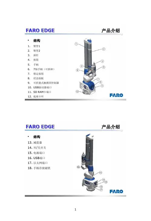
FARO EDGE产品介绍•结构1.臂管12.臂管23.探针4.按钮5.手柄6.7轴手柄(可拆卸)7.锁定按钮8.状态面板9.可折叠式触摸屏控制器B驱动器端口11.SD RAM卡端口12.底座卡环FARO EDGE 产品介绍•结构13.减震器14.开/关开关15.电源端口B端口17.以太网端口18.手柄存放磁铁FARO EDGE 安装操作•底座安装通过手柄拧紧底座卡环FARO EDGE 安装操作•探针安装1.握住EDGE的末端的按钮区域2.顺时针旋转探针,将其旋入注意:安装探针时,切勿在按钮区外的地方握住EDGE。
FARO EDGE 安装操作•探针的放置手柄放置时,确保磁扣对齐、吸住。
FARO EDGE 安装操作•FARO EDGE的7轴1.逆时针旋转松开锁定环2.将7轴手柄的前端插入槽里3.向里推7轴手柄,接好接头4.顺时针旋转拧紧锁定环注意:收起设备时,先卸下7轴手柄FARO EDGE 安装操作•FARO EDGE的电源1.电源开关2.电源端口FARO EDGE 安装操作•触摸屏控制器按下底座顶部的锁定装置可以打开触摸屏控制器。
FARO EDGE 安装操作•电池安装1.将圆的一面朝下滑入电池组。
2.向内推动电池,直至其卡入到位。
FARO EDGE 安装操作•电池拆卸1.向右推动电池组释放杆2.将电池组拉出FARO EDGE 安装操作•电池充电1.Edge 接通电源后,电池组便开始充电。
即使电源为关闭位置,电池组也将充电。
电池组充电完毕后将自动停止。
2.电池组内置有电量表。
按下连接器边上的软按钮,观察 LED 即可了解当前电量。
FARO EDGE操作规程•正确操作1.安装FaroEdge时,注意使用正确的手法进行提拎。
2.如果仪器安装在三脚架上,请确保三脚架上的所有螺纹连接已经拧紧;如果安装在磁力吸盘上,检查并除去磁力座的底部油污或铁屑等杂物;如果安装在真空吸盘上,一定要按说明书正确使用,以免漏气发生一些意外。
FARO Swift 移动扫描仪说明书
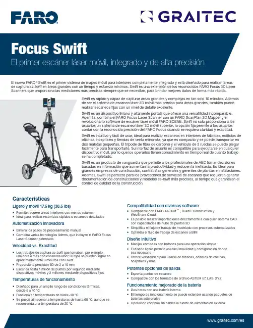
CaracterísticasLigero y móvil 17.5 kg (38.5 lbs)•Permite recorrer áreas interiores con menos volumen•Ideal para realizar recorridos rápidos o escaneos detalladosAutomatización innovadora•Elimina los pasos de procesamiento manual•Combina varias tecnologías líderes, que incluyen el FARO Focus Laser Scanner patentadoVelocidad vs. Exactitud•Los trabajos de captura as-built que tomaban, por ejemplo,una hora o más con escaneos láser 3D fijos se pueden lograr en aproximadamente 6 minutos con Swift •Proporciona precisión 3D de 2 a 10 mm•Escanea hasta 1 millón de puntos por segundo mediante dispositivos móviles y 2 millones mediante dispositivos fijosTemperaturas de funcionamiento•Diseñado para un amplio rango de condiciones térmicas,desde 5 a 40 °C•Funciona en temperaturas de hasta -10 °C•Se puede almacenar a temperaturas de hasta 60 °C, aunque se recomienda una temperatura de 25 °CCompatibilidad con diversos software•Compatible con FARO As-Built ™ , BuildIT Construction y WebShare Cloud•Es posible realizar importaciones directamente a cualquier sistema CAD con capacidades de nube de puntos 3D•Simplifica el flujo de trabajo de modelado con procesos automatizados •Optimiza el flujo de trabajo de escaneo a BIMDiseño intuitivo•Manijas cómodas con botones para una operación simple•El diseño ligero permite una fácil movilidad y configuración donde sea necesario•Ofrece versatilidad para usarse en fábricas, edificios de oficinas,hospitales y másPotentes opciones de salida•Exporta puntos de escaneo•Compatible con los formatos de archivo ASTEM 57, LAS, XYZFuncionamiento mejorado de la batería•Dos horas con una batería interna•El tiempo de funcionamiento se puede extender usando paquetes de baterías adicionales•Operación continua sin cables ni fuente de alimentación externaSwift es rápido y capaz de capturar áreas grandes y complejas en tan solo 10 minutos. Además de ser el sistema de escaneo láser 3D móvil más preciso para áreas grandes, también puede realizar escaneos fijos con un nivel de detalle excelente.Swift es un dispositivo liviano y altamente portátil que ofrece una versatilidad incomparable. Además, combina el FARO Focus Laser Scanner con un FARO ScanPlan 2D Mapper y el revolucionario software de escáner láser móvil FARO SCENE. Swift no solo proporciona a los usuarios un sistema de escaneo láser 3D móvil superior, la opción fija permite a los usuarios contar con la reconocida precisión del FARO Focus cuando se requiera claridad y exactitud. Swift es intuitivo y fácil de usar, ideal para realizar escaneos en interiores de fábricas, edificios de oficinas, hospitales y tiendas de venta minorista, ya que es compacto y se puede transportar en dos maletas pequeñas. El trípode de fibra de carbono y el vehículo de 3 ruedas se puede plegar fácilmente para transportarlo. Su interfaz de usuario es compatible para ejecutarse en cualquier dispositivo móvil, por lo que los operarios tienen conocimiento en tiempo real de cuánto trabajo se ha completado.Swift es un producto de vanguardia que permite a los profesionales de AEC tomar decisiones basadas en información que aumentan la productividad y reducen la ineficacia. Es ideal para grandes empresas de construcción, contratistas generales y gerentes de plantas e instalaciones. Además, Swift es perfecto para los proveedores de servicios de escaneo que requieren generar documentación de construcciones y modelos as-built más precisos, al tiempo que garantizan el control de calidad de la construcción.El nuevo FARO ® Swift es el primer sistema de mapeo móvil para interiores completamente integrado y está diseñado para realizar tareas de captura as-built en áreas grandes con un tiempo y esfuerzo mínimos. Swift es una extensión de los reconocidos FARO Focus 3D Laser Scanners que proporciona las mediciones más precisas siempre que se necesitan, para brindar mejores datos de forma más rápida.BeneficiosIncremento de la productividad•Permite que los operadores de mapeo móvil trabajen de forma más rápida e inteligente, ya que proporciona escaneos de mejor calidad y reduce enormemente el tiempo en la escena y que se destina al procesamiento •Incrementa la productividad, ya que captura los datos as-built 3D mientras el operario camina por una construcción •Fácil de aprender y de usar mediante la guía para usuarios de FAROMejora en la eficacia•No se compromete la máxima precisión y calidad de los datos gracias a la combinación de la captura de datos móvil con el escaneo láser fijo en un mismo dispositivo•Complete escaneos de áreas grandes y complejas en tan solo 10 minutos•Proporciona precisión 3D de 2 a 10 mmMejora en la calidad y confiabilidad•Permite que los usuarios aventajen a la competencia con un producto de mejor calidad y completamente integrado con el ecosistema de productos y software de FARO •El avanzado dispositivo de mapeo móvil brinda un rendimiento incomparable •Probado en condiciones extremas para garantizar la confiabilidad en entornos industriales desafiantes Maximización del ROI•Expande las posibilidades de los FARO Focus Laser Scanners para usarse en más aplicaciones•Dispositivo intuitivo y fácil de usar, con una curva de aprendizaje mínima•Garantía excepcional, bajos costos de mantenimiento•Cambie entre el modo de escaneo móvil o fijo para abarcar un área más grande o capturar más detalles1 Para la dispersión lambertiana, se usó Focus S 350 o Focus S Plus 3502Para los escaneos fijos, el rango de ruido se define como la desviación estándar de los valores con respecto al plano mejor adaptado para la velocidad de medición de 122 000 puntos/seg. 3En un ambiente interior controlado 4Según el ambiente escaneado 5Incluye el carrito, el trípode y los montajes de Swift, el Focus S Scanner y ScanPlan 6Temperatura baja de funcionamiento: Los dispositivos deben encenderse cuando la temperatura interna sea mayor a los 15 °C 7El almacenamiento extendido a temperaturas mayores a 40 °C puede afectar el rendimiento y la duración de la batería. 8Con FARO SCENELa precisión depende de la eficacia del algoritmo de registro SLAM, la cual puede ser afectada por la geometría del entorno capturado. Los trayectos extensos sin cierres, los cruces y las diferentescondiciones, como corredores estrechos o la presencia de ventanas o paredes de vidrio, pueden afectar la precisión. Si busca más información, consulte la hoja técnica de los escáneres Focus S /Focus S Plus y ScanPlan. Todas las especificaciones de precisión tienen una desviación de 1 sigma, se realizan después del calentamiento y dentro del rango de temperatura de funcionamiento, a menos que se especifique lo contrario. Sujeto a cambios sin aviso previo. Swift solo está disponible para los escáneres Focus S y Focus S Plus, requiere ScanPlan, accesorios y licencias adicionales de FW/SW, requiere SCENE versión 2020o posteriores y el firmware 6.6 o posterior de Focus.。
FaroSTEAM 烟雾净化器用户指南说明书

Faro STEAMInstruction ManualRev 0.0 Edition 2020/05Table of Contents1 WARNINGS AND SAFETY REGULATIONS (3)1.1 Before use (3)1.2 Safety Warnings (3)2 TECHNICAL DATA (4)2.1 Protection devices: (4)3 INSTRUCTIONS FOR USE (5)3.1 Description of the appliance and accessories (5)3.2 Controls (5)3.3 Setup (5)3.4 Fitting the Accessories (6)3.4.1 Flexible hose with Grip (6)3.4.2 Short black lance (direct connection with th flexible hose) (7)3.4.3 Circular brush (7)3.4.4 Multifunction Brush (7)3.4.5 Extension hoses (7)3.4.6 Sanix (8)3.5 Using the Steam Generator (8)3.5.1 Before Cleaning (8)3.5.2 After Cleaning (8)3.5.3 Cleaning with steam lance (9)3.5.4 Cleaning floors (9)3.6 Lack of water (9)4 MAINTENANCE (9)4.1 Removal of lime scale deposits in the steam generator (9)4.2 Cleaning of the appliance (10)5 DISCLAIMER (10)6 DISPOSAL OF WASTE OR RECYCLING (10)1WARNINGS AND SAFETY REGULATIONSStrictly follow the instructions and recommendations for maintenance that are the basis of the intended use.In case of improper use or failure to comply with the instructions for use, any warranty will not be recognized.1.1Before useOnce the appliance is unpacked, check that no visible damages are present. In case of doubt, do not use the appliance and contact your service center.The device is accepted for repair only if equipped with the ORIGINAL PACKAGING. Do not throw the original packaging.1.2Safety Warnings∙The appliance must only be used for its intended use.∙Before start the using od the appliance, read this manual completely and carefully.∙Any use of the appliance in contrast with the instructions in this manual will result in the loss of the warranty.∙The appliance must be connected only to domestic or professional electrical circuits conform to national and international safety standards.∙Do not use the appliance at extreme temperatures. The appliance must be used in a temperature range between +5 ° C and +40 ° C.∙Before connecting the appliance, make sure that the socket is safe and provided with three poles earthed.∙The energy consumption of the appliance can be seen on the mainplate located on the bottom of the appliance.∙Do not leave the appliance unattended. Even in the case of short breaks during work, disconnect the plug from the socket.∙Before handling the appliance, remove the plug from the socket.∙Do not unplug the appliance by pulling on the power cable.∙Protect the power cable from twists, breaks and sharp edges. Keep it away from heat sources.∙Do not use the appliance if the power cable or the appliance itself is damaged.∙Do not use an extension cord without a Safety Mark, and in no case use cable reels.∙If you need to replace the power cable, contact your service center.∙The appliance is equipped with a thermal protection switch which can only be activated or replaced by the manufacturer or an authorized service center.∙If the appliance is damaged or does not work properly, it must be turned off immediately. Do not perform any kind of intervention.∙For repairs, contact the manufacturer or your dealer.∙If the power supply cable of the appliance is damaged it should be immediately replaced by the manufacturer or authorized service center.∙Never use the appliance with wet hands or feet.∙Do not use the appliance nearby sinks, bathtubs, showers or tanks full of water.∙Do not dip the appliance, the cable or the plug in water or other liquids.∙It is forbidden to use the appliance in explosive environment or rich of oxygen.∙Do not use the appliance nearby toxic substances.∙Do not use the appliance on surfaces or objects sensitive to heat.∙Do not expose the appliance to atmospheric agents.∙Do not place the appliance near heated boilers, electric heaters or near heat sources.∙Appliances such as televisions, radios, lamps, etc. they must not be cleaned with steam, even when they are not connected to the mains.∙The appliance must not be used by children.∙Do not press the buttons with excessive force and avoid the use of sharp objects .∙Always place the appliance on a stable base.∙If the appliance falls from above and /or is damaged, stop using it and contact your service center.∙In case of no steam delivery or appliance failure, turn it off and never try to repair it by yourself.Contact your service center.∙In case of repair, use only original spare parts.∙When filling the appliance with water, unplug the power plug.∙Always keep the appliance horizontal.∙Never direct the steam jet into or towards electrical appliances.∙Before cleaning the appliance, always unplug the power cord.∙Always wait for the appliance to cool before storing it.∙Always empty the boiler if the appliance has not been used for more than three weeks.∙This appliance has several safety systems, which can only be changed by an authorized service center.∙Never direct the steam jet towards people or animals.∙Never touch the steam jet by hand.∙Never fill the water tank of the boiler with cleaning detergents or other additives. Use only tap water.∙This appliance is not suitable for use by people (including children) with physical, sensory, mental disabilities or who do not have the necessary competence or knowledge of use of the appliance.∙Watch children to make sure they do not play with the appliance.The manufacturer declines all liability for damage arising from improper or incorrect use of this appliance 2TECHNICAL DATAPower supply 230 Vac - 50/60 HzNominal Power 1700 WWater tank capacity 2.7 lMaximum pressure 3,9 barNet weight 4.5 kgElectrical control of steam 3 levels on grip of flexible hoseDimensions (mm) 440 x 280 x 265Approved Type ML7Q67004717 SD-1Manufacturer General Vapour srl - Strada per Castelletto, 19-2120080 Albairate (MI) Italy2.1Protection devices:∙Overpressure valve∙Protection class IP 24∙Electronic control of heating power∙Electronic control of the water level in the boiler∙Electronic control of water level in the water tank∙Automatic reset thermostat∙Thermal fuse3INSTRUCTIONS FOR USE3.1Description of the appliance and accessories1.Steam generator2.Cable compartment3.Flexible hose4.Extension hoses5.Safety cap6.Multi-function brush8.Brush for padded products(sofas, carpets, car seats, etc.)9.Squeegee (optional)10.R ectangular brush pad11.S hort black lance12.R ubber nozzle13.C ircular soft brush brush (Ø30 mm)14.C ircular brush with nylonbristles (Ø 60 mm)15.C ircular brush with steelbristles (Ø 30 mm)16.C ircular brush with bronzebristles (Ø30mm)17.C ircular brush with nylonbristles (Ø30mm)18.T riangular brush pad19.C leaning cloth20.B ottom3.2ControlsA Main SwitchB Working pressure lightC Light indicating voltage levelsD No water Light Steam adjustment:Power 1: press GPower 2: press F (G not pressed)Power 3: press F + G3.3SetupPlace the appliance on a flat surface.Unscrew the safety cap.Fill in the boiler with water using the tunnel. NOTE: The boiler holds 2 litres.Only fill the boiler with tap water.Never add detergents or other chemical additives. The “safety cap valve” has a special self- locking device that cannot be opened when the appliance is under pressure.Completely unwind the power cordPlug into earthed socketATTENTIONThis machine cannot be used for more than 3 hours continuouslyPress the main switch (A).the light on the main switch when the aplliance is switched OnWait for the light (B) to light on.The green light shows that the working pressure has reached the maximum level3.4Fitting the Accessories3.4.1Flexible hose with GripPress (F, G) on the grip to adjust the quantity of the steam. To enable the steam pull the trigger on the flexible grip. Lift the socket Cover on the steam cleaner.Insert the plug (H) in the socket on the appliance.Check that the plug (H) is correctly inserted (pull).3.4.2Short black lance (direct connection with th flexible hose)Insert the shrt lance on the grip of the flexible hose. Takecare that the connection clip E is inserted correctly into itsseat D.3.4.3Circular brushInsert the brush on the short lance3.4.4Multifunction BrushPut the stopper in middle position“Free” (K).insert the brush on the universalcurve joint.Move the stopper (K) to the left forposition “Movable” or to the right inposition “locked”.When the stopper is in positionMovable the brush can rotate of 180°arund the universal joint.When the stopper is in positionLocked the brush cannot rotatearund the universal joint.3.4.5Extension hosesInsert the extension hoses directly on the grip of the flexible hose.Take care that the connection clip is inserted correctly into its seat.3.4.6SanixSanix contains 0.5 lt of liquid and must be used at speed 3.The flow of steam in the upper part generates a venturi effectand the liquid is delivered together with the steam.Different detergents can be inserted inside Sanix depending onthe result you want to achieve.The liquid is slightly superheated in contact with the steam,when it reaches the surface it will be almost at roomtemperature.Sanix creates a jet of about 1 meter with a diameter of 30 cm.Use it at a distance of about 50/70 cm from the surface in orderto have an homogenous distribution.3.5Using the Steam Generatoraccessories.Before use, adjust the steam to power 2-3 (§3.2) and let the appliance run for a few seconds.Never use the appliance to clean non-heat-resistant materials.Never leave the steam switch in position 3 for a long time . The normal position 2 is sufficient and consumes less energy.If the soil is hard, the first phase will take more time and more cloths could be needed for the normal use of the steam generator.3.5.2After CleaningAlways turn off the boiler heating switch.Drain all the steam from the boiler. Otherwise the safety cap will not open.Remove the power plug.Before storing the appliance, wait until it has completely cooled down.If you will not use the appliance for 2 weeks, empty out any water left in the boiler, as described in the "Lime scale Removal" section § 4.1.3.5.4Cleaning floorsApply an absorbent cloth on the multifunctional brush.Press the steam button (Power 1-2, see §3.2Clean the floor without making excessive pressure.To clean very dirty floors and remove stains, use the brush without of the cloth .It is not necessary to rub excessively: the steam is sufficient to dissolve the dirt.Apply a cloth on the brush and remove the dirt.NOTE: Move the cloth regularly on the brush in order to always use a clean part of the cloth itself. 3.6Lack of waterThe lack of water in the boiler will be indicated by a red light (§3.2)In this case the heating stops automatically.What to doTurn off the boiler heating switch.Continue to work until all the water remaining in the boiler has been used. If necessary, the self-locking valve cover cannot be opened. If some water remains into the tank it will not be possible to open the cover with self locking valve.Turn off the main switch.Disconnect the plug.Unscrew carefully the boiler cover, to allow the residual steam to get out from the boilerFill the boiler with water as described in § 3.3 SetupReconnect the appliance and start-up as described in point §3.3 Setup4MAINTENANCEAlways remove the plug from the socket before carrying out cleaning and maintenance on the appliance. The following operations must only be carried out by competent and trained people!In any case, it is recommended to contact our authorized assistance service.4.1Removal of lime scale deposits in the steam generator∙According to the degree of hardness of the tap water, the machine must be cleaned of lime scale deposits every 3-4 weeks.Proceed as follows with the appliance cold and not under pressure!∙Remove the plug from the socketWARNINGNever use chemicals to clean lime scale or during normal operation.The appliance requires regular checks and maintenance on various parts of it, these operationsmust be carried out by specialized technicians of our company.These checks are carried under payment.4.2Cleaning of the applianceClean the appliance and accessories with a wet cloth. Never use steam or dip in water.5DISCLAIMERThis manual contains the information necessary for correct use, correct handling and qualified technical support for the maintenance of the machine.The knowledge and observation of what is indicated in this manual represents the condition for safe operation and safe maintenance to be performed on the appliance.Of course, this manual may not contain all the possibilities of use.If you would like further information or have other questions, please contact the Distributor:FARO SpAVia Faro 1520876 – Ornago (MB)Italywww.faro.it6DISPOSAL OF WASTE OR RECYCLINGTo dispose the appliance as special waste according to regulation 2012/19/UE on WEEEContact the public points for the disposal and recycling of the waste or to the dealer.The crossed-out container symbol on the appliance indicates that at the end of use, the product must be removed separately from other waste.For this reason, the user must deliver the appliance that will no longer be used in the appropriate centers for the separate collection of electric and electronic waste or return it to the point of sale when purchasing a new appliance or similar type.The adequate collection of ff differentiated appliances, subject to recycling, preparation and removal as waste, does not harm the environment, contributes to avoiding any negative impact on the environment and health. In addition, the secondary reuse of the materials from which the appliance was made is favored.。
法如激光扫描仪手册1

FARO® LASER SCANNER FOCUS3D 2011 年 10 月
©FARO Technologies Inc., 2011. 保留所有权利。 未经 FARO Technologies, Inc. 书面许可,禁止以任何形式或方式复制或转 载本出版物的任何部分。 FARO Technologies Inc. 不做任何涉及 FAROARM、FARO LASER TRACKER 及其材料的明示或暗示保证,包括但不限于适销性或适用于某特殊用途的 任何暗示保证,而且仅在 “ 按原样 ” 的基础上提供此材料。 因购买或使用 FAROARM、 FARO LASER TRACKER、 FARO LASER SCANNER 或其材料而引起的相关的,或由此产生的特殊的、间接的、偶 然的或继发性的损坏, FARO Technologies Inc. 对任何人概不负责。无论以 何种方式履行, FARO Technologies Inc. 的唯一赔偿责任不超过本文所述材 料的购买价格。 本手册所包含的信息如有更改,恕不另行通知,且不代表 FARO Technologies Inc. 的任何承诺。客户接受本文档即表示认可在英文版与非英 文版之间出现不一致时以英文版为准。
设置界面语言 ...................................................................................35 设置日期和时间 ................................................................................35 设置日期格式 ...................................................................................36 更改日期和时间 ................................................................................37 设置长度单位和温标 ........................................................................38 输入扫描仪信息 ................................................................................38
FARO 城市通勤头盔使用说明书
1W elcome to the UNIT 1 familiy .Congrats!Y ou are among the first to ever experience F ARO.This embodies the work of creators, designers, engineers and entrepreneurs trying to build something unique. F ARO is our best shot at what an urban commuter helmet should be and our small input towards making the roads safer .Y ou are now a part of this story - you helped mak e this happen. W ear it with pride.IMPORT ANTPlease read this manual carefully before using your helmet.2Do not use the helmet in direct sunlight, or very warm places for a long period of time. This can damage the product and generate heat that can cause serious injuries. Do not leave the product near open flames. Do not dispose de product in a fire. This can damage the battery, explode or ignite and cause serious injury. Never charge the helmets battery with a flawed charger, it may cause an explosion oringition. Battery life may vary depending on conditions, environmental factors, usage, etc.Please note some countries require the use of regular cycling lights. If this is the case, F ARO may not replace them. Before using F ARO, mak e sure you comply with local laws and regulations.1. Safety information3 WARNINGF ARO was made for non-motorized recreational pedal cycling only. No helmet can prevent against allinjuries. Serious injury or death may occur while cycling even with a helmet. Unit 1 Gear, Inc. and/or its subsidiaries mak e no claim that this helmet will eliminate all posibilities of injury.Lights are a supplement (not a replacement) of regular mount ed bik e lights. Certain places hav e laws that require lights, comply with local regulations. T urn signals are supplements, not a replacement of hand signals.Unit 1 Gear, Inc. and/or its subsidiaries are not responsible f or any f ailure of communication resulting from turn signals or brak e lights. Lights are no guarant ee againts pre venting an accident or collision.When activating the turn signal, at glance the remote to ensure that you activated the correct turn signal.Activating the wrong turn signal can increase the risk of an accident. If using the turn signals in manualmode, always remember to turn off the signal once used.This hemet was not designed for motor vehicle use, neither for sporting. Everytime you use this helmetcheck if nothing is torn, worn, missing, or out of adjustment. This helmet should not be used by children.Y our helmet has a built-in battery. Be careful to follow all the safety guidelines.2. Package content 41. F ARO Helmet2. USB Type-C / T ype-A3. Navigationremote (optional)3. Overview 51.1 Front light / 1.2 MIPS liner (optional) / 1.3 Magnetic buckle / 1.4 Back light / 1.5 Hidden lights / 1.6 Power button / 1.7 Charging port / 1.8 Fitting system4. Fitting instructionsA correct fitted helmet should sit comfortably on your head without pressing or chafing and should not move foward to obscure your vision or reaward to expose your forehead. Please mak e sure the helmet is positioned the right way .Be sure to position the buckle under the chin and back against the throat. The straps should fit comfortably around your ears. T est these adjustments before every ride. 6How to wear your helmet F ARO has a great fit. Follow these instructions carefully to aply your helmet correctly . Consult us if you are not sure which features your helmet has.Adjust your bucklesT o lock the Magnetic buckles bring the two parts together until they snap. T o unlock them, slide them sideways as shown below. T o k eep the chinstrap from loosening or flapping, it must be tuck ed through the k eeper.Fitting systemTighten or loosen the Fitting system dial to fit the circumference of your head as required.785. Function guide UNIT 1 App By simply pairing your phone with your Bluetooth system, you can use the F ARO app for quick er , easier setup and management.Apple Store Google PlayDownload Android: Google Play Store > F ARO appiOS: App Store > F ARO app or scan the QR code below .Power on / off Press& hold the power button for 1 sec.9Action with power button Helmet functions overview - Press & hold the power button for 1 sec: Power On / Off- 4 taps: Helmet reset- 8 taps: Full factory reset (forgets app and remote)10Pull and turn the silicone lid. Then plug the USB-C cable into the charging port. Once plugged in the hidden lights will display the status of your battery using 6 levels. All 6 levels in a solid green color mean the battery is full. For safety purposes,F ARO functions are not avaliable while charging. DO NOT use the helmet while charging with a powerbank.Charging3.1.2.Pairing F ARO with the U1 App 1. Mak e sure your phone’s bluetooth connection is active.2. Power up your helmet3. Look for your helmet using the U1 App4.Pair directly from the U1 App11TroubleshootingIf you are having trouble with your helmet, follow these steps.Charge the helmet using the USB-C cable.Not powering onMak e sure your helmet is fully charged and your bluetooth connection is active.Not pairingReset the helmet by pressing the power button for 5 times.Helmet not respondingMak e sure the USB-C power source is switched on and plugged correctly .Not charging1. Power on your helmet (should be off before you begin)2. Press & hold any button on the Nav Remote (lights will blink left & right)3. W ait for connection. Helmet will show 3 green flashes when complete, Nav Remotewill also flash 3 times.6. Navigation remote12EN3.1 Navigation remote / 3.2 Dock / 3.3 Rubber pad / 3.4 Rubber bandInstallationA ttach the dock to your handlebar using 1 of the rubber bands included in the package. Do so by looping the band in the center of the dock as shown below . Place the remote on the dock and twist it clockwise to lock it into place.The navigation remote is an optional feature.3.43.33.23.11314Pairing your Navigation Remote1. Start with both Helmet & Nav Remote OFF and close to each other (Fig 1.)2. Power on your helmet3. Press & hold any button on the Nav Remote (lights will blink left & right) (Fig 2.)4. Helmet will show 3 green flashes when complete and Nav Remote will flash 3 times when connection is made (Fig 3.).5. Y our remote will stay paired to your helmet unless you replace it by another one or perform a factory reset of your helmet.Action with L&R buttonNavigation remote function overview - 1 tap (L or R):Turn signal Activation- hold 3 secs: System resetIf set on Automatic , turn signal will endautomatically after designated time If set on Manual , T urn Signal will end by tapping any button (L or R)Fig 1.Fig 2.Fig 3.15ENPull and turn the silicone lid. Then plug the USB-C cable into the charging port. Use the same cable than the helmet.ChargingTroubleshootingIf you are having trouble with your Navigation Remote, follow these steps.Not powering onCharge the remote using the USB-C cable.Not chargingMak e sure the USB-C power source isswitched on and plugged correctly . The LED indicator will display a slow pulse when charging.Not pairingMove the device closer to each other and away from any interference or obstruction.Mak e sure the helmet is not connected to another remote when entering pairing mode.Remote not respondingReset the remote by pressing & holdingeither button for 3 seconds.3.1.2.5. More aboult your helmetGeneral safetyNo helmet can protect the wearer against all posible impacts. A severe impact, sharp object,imporoper use, or incorrect adjustment could cause conditions beyond the protection of the helmet.T o be effective, a helmet must fit and be worn correctly. The helmet is designed to be retained by a strap under the lower jaw. T o check for correct fit, place the helmet on your head and mak e anyadjustments inducated. Securely fasten retention system. Grasp the helmet and try to rotate it to the front and rear. A correctly fitted helmet should be comfortable and should not move foward toobscure vision or reaward to expose the forehead. Failing to properly position the helmet can result in sereious injury to you or others.The helmet is designed to absorb shock by partial destruction of the shell and liner. This damagemay not be visible. Therefore, if subjected to a severe blow, the helmet should be destroyed andreplaced even if it appears undamaged. The helmet has a limited lifespan in use and should bereplaced when it shows obvious signs of wear. Helmets parts lose strength over time, so even if the helmet has not been impacted or damaged, replace it after three years.RegulatoryF ARO was designed to comply with most International Safety Certifications and meets C.P.S.C. 16 CFRPart 1203 United States Federal Safety Standard for Bicycle Helmets (Consumer Product SafetyCommission) and with the CE, EN1078:2012 +A1:2012 Helmets for pedal cyclists, Skateboarders or Rollerskaters (European Safety Standard).1617SPECIFICA TION OF RADIO TRANSMISSION FCC ST A TEMENTF AROF ARO Navigation Remote PRODUCT: F ARO_HELMET F ARO_REMOTE MODEL NUMBER: 2402 - 2480MHz 2402 - 2480MHz OPERA TING FREQUENC Y:DC 3.7V 1850mAHDC 3.7V 100mAHPOWER:The above product is in conformity with the PPE Regulation(EU) 2016/425 and is identical to the PPE which is subject of EU certificate (TBC) issued by ITS T esting services UK LtdThis device complies with Part 15 of the FCC Rules. Operation is subject to the following two conditions:(1) This device may not cause harmful interference, and(2) This device must accept any interference received, including interference that may cause undesired operation.W arning: Changes or modifications not expressly approved by the party responsible for compliance could void the user’s authority to operate the equipment.The above product is in conformity with the European Radio Equipment Directive (RED) (2014/53/EU) which is subject of EU certificate (TBC) issued by T eleficationY ou can find the declaration of conformity by the following links:Bluetooth LEMaximum Output Power: 0dBm EIRP A verage (Calculated)Maximum Antenna Gain: 1dBi www .unit1gear .com/EU_DoCNOTE: This equipment has been tested and found to comply with the limits for Class B digital device, pursuant to Part 15 of the FCC Rules. These limits are designed to provide reasonable protection against harmful interference in a residential installation. This equipment generates uses and can radiate radio frequency energy and, if not installed and used in accordance with the instructions, may cause harmful interference to radio communications. However, there is no guarantee that interference will not occur in a particular installation. If this equipment does cause harmful interference to radio or television reception, which can be determined by turning the equipment off and on, the user is encouraged to try to correct the interference by one or more of the following measures:Reorient or relocate the receiving antenna.Increase the separation between the equipment and receiver.Connect the equipment into an outlet on a circuit different from that to which the reciver is connected.Consult the dealer or an experienced radio/TV technician for help.RF W ARNING ST A TEMENT:The device has been evaluated to meet general RF exposure requirement. The device can be used in portable exposure condition without restriction.-English:”This device complies with Industry Canada license-exempt RSS standard(s). Operation is subject to the following two conditions:(1) This device may not cause interference, and(2) This device must accept any interference, including interference that may cause undesired operation of the device.”18Helmet careStore your helmet in a dry place, away from excessive heat soulrces lik e radiators, automobile trunks or direct sunlight. Clean your helmet only using a slighty damp soft cloth or sponge.The helmet can be damaged using chemical cleaners, specialy petroleum base solvents.Replace your helmet if there is any sign or hint of damage, DO NOT use a damaged helmet. Using a damaged helmet or worn may result in more serious injuries in the event of a fall.Inner pads are removable and can me washed by hand with mild soap and water, rinsed and dried. The protection of this helmet may be severly reduced by the aplication of paint, adhesive stick ers and transfers, cleaning fluids, chemicals, and other solvents.Never remove or modify the original elements that constitute the helmet, or add any accesories not recommended by Unit 1 Gear, Inc., this may affect the protection given by the helmet.Store in a dry place, away from heat (for example, sunlight through a car window) .196. W arranty1 year limited warrantyUnit 1 Gear, Inc. warrants to the original purchaser of this product that the product is free of defects in material and workmanship for a period of (1) year from the original date of purchase. This warrantydoes not apply to defects of physical damage resulting from abuse, neglet, improper repair,improper fit, alterations, or use unintended by the manufacturer.If your F ARO is found to be defective in materials or workmanship within one year from the date of purchase, Unit 1 gear, Inc. will at its sole option either repair or replace the helmet free of charge. Unit1 Gear, Inc. does not warrant any helmet damaged due to heat or contact with solvents. Thiswarranty does not affect your statutory rights. This warranty is in lieu of all other agreements andwarranties, general or special, express or implied and no representative or person is authorized to assume liability on behalf of Unit 1 Gear, Inc. in connection with the sale or use of this product.This limited warranty only applies to products purchased directly from Unit 1 Gear, Inc. official stores or a Unit 1 Gear, Inc. authorized reseller.This limited warranty does not cover normal wear and tear.Unit 1 Gear, Inc. does not offer warranty regarding battery life used in F ARO. Battery life may varydepending on its configuration and use. Unit 1 Gear, Inc. does not guarantee or promise any specific level of performance or battery life associated with the use of its product or any feature in it.2021contact@unit1gear .comUnit 1 Gear , Inc.3411 Silverside Road, Rodney Building #104Wilmington. DE 19810USA.www .unit1gear .com/unit1news/u1gear/unit1gear。
FARO悬挂电机套件用户手册说明书
HANGING MOTORS KITDear Customer,FARO wishes you success with your new suspended laboratory engine.To work safely and to take full advantage of the product's performance, please read this manual carefully before using the device. In particular, please follow all warnings and notes described in the Safety Recommendations .Warranty Conditions:FARO offers the end customer a warranty of 12 months from the date of installation up to a maximum of 18 months from the date of manufacture.Warranty repairs must be carried out by FARO or its approved service network. The guarantee is considered valid only when:• theuserhassentthedulycompletedCertificateofWarrantytothefollowinge-mailaddress:***************• the user registered the guarantee through the Faro website;The guarantee covers manufacturing and engineering defects; in the event of a valid claim, the guarantee only covers the free replacement of parts. Manual work is not included in the guarantee.The guarantee shall not be considered valid, at FARO's sole discretion, if the defect is due to tampering, damage, unauthorised modifications to the product, improper use, incorrect maintenance and normal wear and tear.This product has a service life of: 10 years.1SAFETY REGULATIONSThe 486500 laboratory motor meets the directives2006/42/EC - 2014/35/EU - 2014/30/EU - 2016/425/EU1.1SYMBOLS USED1.1.1 symbols used within the manualWARNINGPROHIBITIONParagraphs marked with this symbol contain instructions that must be followed carefully to avoid damage to the device or the operator .This icon highlights what not to do to avoid damage to the device.ATTENTIONNOTESGreat care must be taken to avoid situations that could damage the device.With this icon, information is provided that allows the device to be used more effectively.1.1.2 Labelling And Packaging SymbolsSymbolDescriptionSymbolDescriptionSymbo lDescriptionEuropean Conformity MarkUse the device at atemperature between 10°C and 40°CFragileRead the instructions for use. Supplied electronically.Use the device at a pressure between 80 kPa and 106 kPaProtect packaging from rain and high humidityInstructions for use include safety warningsUse the device at a relative humidity between 30 RH and 75RHDo not rollWEEE equipment according to Directive 2012/19/EC. Double insulation. Class 2 device against electrical hazards Do not use hooksRecyclable cardboardLot numberHigh1.2Intended UseElectronically-controlled laboratory motor with flexible shaft for use in dental laboratories, goldsmiths' workshops and mechanical tooling for finishing workpieces.1.3Main Safety Warnings•Follow all directions in the following manual.•It should only be used by trained personnel.•Disconnect the power cable from the mains during maintenance work.•Do not perform maintenance operations on the flexible shaft when the motor is rotating.•Do not introduce foreign objects into the flexible shaft connection.•We recommend wearing appropriate clothing, goggles and protective clothing when using the engine.•Tighten the ring nut securing the flexible shaft to the motor.•Avoid blocking the cutter d u r i n g use.•Use thermal protective gloves in case of excessive temperature.•Only use handpieces capable of withstanding a maximum number of revolutions equal to those of the motor.•Only use handpieces with a suitable connection to the flexible shaft.•Do not perform maintenance operations other than those described in the manual.2DESCRIPTION OF PARTS AND CONTROLS1.Motor.2.Motor power cable.3.Flexible shaft.4.Rheostat (Standard or Contronic)5.Mains power cable6.Rheostat pedalModel 486500Model 486750Differences from 486500 highlighted in B):fig. 1 presence of separation band between upper and lower dome•Presence of label on the upper shell3INSTRUCTIONS FOR USECheck that all components of the suspended motor are contained in the package:•Rheostat.•Motor.•Flexible shaft.•Documentation.3.1ENGINE INSTALLATIONA.Fasten the stand firmly and securely to the bench.B.Secure the motor to the bracket, locking it with the appropriate screw pin.C.Connect the flexible shaft to the motor, taking care to insert the gears properlyD.Tighten the ring nut firmly. Ensure that the ring nut is compatible with the motor:•For motor 486500 ring nut code 082001•For engine model 486750 use ring code 486758fig. 2DANGER OF DISENGAGEMENT OF THE FLEXIBLE SHAFTFerrules 082001 on 486500 motors are not compatible with ferrules 486758 on 486750 motors. The visual difference lies in the presence of a passage scan ('A') on 082001 not present on 486758.F.Insert the power plug into the power socket.DANGER OF OVERHEATINGBefore plugging the plug into the power socket, make sure that the mains voltage corresponds to the voltage stated on the name plate of the rheostat.3.2 ENGINE START-UPDANGER OF DISENGAGEMENT OF THE FLEXIBLE SHAFT OR HANDPIECERun the engine idle for a few seconds, ensure correct operation.In the event of abnormal noises or loose connections, disconnect power to the motor3.3 SPEED ADJUSTMENTThe speed by stopping the rheostat pedal to the right for minimum speed and to the left for maximum speed4 MAINTENANCE4.1 Replacing Carbon BrushesWhen it becomes necessary to replace the carbon brushes, proceed as follows: Disconnect the power plug.Remove the top cover, using a 3 mm hexagonal key, to unscrew the two screwsblocking it (fig. 2).Straighten connection terminal 'A' (Fig 3-4) and pull it out of the connector. Fig 3) Replace the carbon brushes (fig. 2).Replace connector 'A' in the housing and fold it back to ensure it is tight (Fig. 3),Replace the cap, securing it with the two screws (Fig. 2).DANGER OF MALFUNCTION It is important not to reverse the connection wire of the carbonbrushes, as this would rotate the motor in the opposite direction!Fig 4)4.2 FUSE REPLACEMENTThe fuse is located inside the rheostat and the hexagonal screw on the top of the cover must be removed to remove it.5 GUIDE TO THE MOST COMMON PROBLEMSThe engine does not run.Check that the power plug is inserted into the socket and that the socket is working properly. Check the state of the fuse in the rheostat.Disconnect the flexible shaft from the motor and try again.If it works now, the fault lies in the flexible shaft or the handpiece.Check the wear condition of the carbon brushes and replace them if necessary Consult technical assistance.The motor turns regularly, but there is no transmission of motion to the flexible shaft.Disconnect the flexible shaft from the motor and check the integrity of the transmission gears located between it and the motor. Please contact technical support for possible replacement.Motion is transmitted regularly to the flexible shaft, but the handpiece shaft does not rotate. Disconnect the handpiece from the flexible shaft and check the transmission status. Please contact technical support for possible replacement.6TECHNICAL SPECIFICATIONS6.1ENGINE SUSPENDEDModel ; 486750Speed 22,000 rpm (no-load speed)Supply voltage 230 V ACMains frequency 50 / 60 HzPower :280 WMax. current consumption : 2 AMax. torque : 11 N-cmNoise level 75 dB (A) maxEngine weight 2.6 kgElectrical hazard protection class II (double insulation)Degree of protection : commonType of operation : continuous alternating loadWorking temperature from 040°C6.2REOSTAT:Speed 8,00022,000 rpmSupply voltage See motor specificationFuse: T 3.15 A6.3CONTRONIC' RHEOSTATSpeed : 3,00020,000 rpmSupply voltage See motor specifications Fuse : T 3.15 A6.4FLEXIBLE SHAFTSpeed 22,000 rpmType of connection towards gear motor- towards the normal slip handpiece FARO S.p.A.via Faro, 15 - 20876 Ornago (MB) - Italy Tel. +39 039.68781**************************************@faro.itFARO FRANCE SAZa Tgv Coriolis - 71210 Monchanin - France Tel. +33 385.779680********************************************FARO SpA reserves the right to change, without notice, the specifications indicated in this manual. FARO SpAreserves the right to change the specifications of this equipment without notice.FARO SpA se reserve le droit de modifier, sàns préavis, les caractéristiques dans ce manuel.FARO SpA behält sich rechtvor, jederzeit stillschweigend technische oder bauliche Änderung worzunehmen.FARO SpA se reserva el derecho de modificar sin aviso previo la caracteristicas incluidas en el presente manual de uso.。
FAROARM三坐标测量机基本操作过程
FARO ARM三坐标测量机基本操作过程一.重型三角架1.1三角架底座的移动1.1.1升起三角架底座1.1.1.1脚踩在脚踏板上,将其向下并朝向三角架中心压动,同时握住三角架稳定杆,向上提起,使三角架底座升起,确定只有滚动轮接触地面,以便将三角架移动到需要的位置。
1.1.1.2将脚从脚踏板上移走,脚踏板将锁定在适当位置。
1.1.2 降下三角架底座:脚踩在脚踏板上,将其向下并向三角架中心向外压动,使三角架的底座下降,滚动轮回缩,然后,弹起脚踏板。
1.1.3 固定三角架:手动调整三个调整螺钉,直到平稳,然后用扳手将三角架底座上的锁紧螺母锁定,防止三角架在不平坦的地面摇晃。
1.2调整三角架1.2.1升起三角架立柱1.2.1.1将锁紧手柄逆时针方向旋动,放松夹具,使立柱可以上下移动。
1.2.1.2逆时针方向旋动升降手柄,调整三角架立柱到希望高度。
1.2.1.3锁紧锁紧手柄,推下顶舌,使立柱固定不动。
1.2.2降低三角架立柱1.2.2.1将锁紧手柄逆时针方向旋动,放松夹具,使立柱可以上下移动。
1.2.2.2逆时针方向旋动四方手柄大约1英寸,将顶舌抬起。
1.2.2.3顺时针方向旋动四方手柄,使立柱降低。
1.2.2.4锁紧锁紧手柄,使立柱锁定在固定位置。
二.安装FARO ARM:正确的安装方法是保证测量精度的基础。
2.1将快速安装卡盘安装到三角架底座安装面板上,拧紧固定螺栓。
2.2将FARO ARM的下底座安装到快速安装盘上,并用扳手拧紧。
2.3选择所需用的测头安装到FARO ARM上,注意用力适度,以免损伤螺纹和影响测量精度。
2.4注意:三角架最好安装在水平面上,坡度较大时要防止ARM 坠落摔伤。
ARM暂时不用时要把第2和第6关节相对放置,并用臂固定贴固定好。
三.选择相应的校准器(球校准器或锥校准器),并固定在FARO ARM臂长的1/2-2/3范围处,以备FARO ARM校准之用。
四.连接计算机和FARO ARM4.1将端口锁(加密狗)插入到计算机的USB接口上,以授权CAM2正常运行。
法如(FARO)柔性臂测量机及PI软件在检具上的应用手册
分类代码:备案号:法如(FARO)柔性臂测量机及PI软件应用手册目次前言 (III)1范围 (4)2规范性引用文件 (4)3术语和定义 (4)4参考文献 (4)5测量条件 (4)5.1环境条件 (4)5.2操作条件 (4)5.3系统条件 (4)5.4设备点检 (5)5.5设备连接 (5)6测量要求 (7)6.1检具数模要求 (7)6.2检具恒温要求 (7)6.3底板相关项目要求 (7)6.4检具基准要求 (7)6.5检具的制造精度要求 (7)6.6检具常规标识要求和测量构成部分 (8)6.7测量元素的测量要求 (9)6.7.1本体面的测量要求 (10)6.7.2检测线的测量要求 (10)6.7.3定位的测量要求 (10)6.7.4检测销的测量要求 (11)6.7.5检测块的测量要求 (12)6.7.6卡板的测量要求 (13)6.7.7基准块的测量要求 (13)6.8数模颜色与测量精度 (14)7测针校准 (14)7.1探测误差校准方法的原理 (14)7.2取点原则 (14)7.3测量结果的处理 (14)7.4操作流程 (14)7.5注意事项及结果查看 (15)8建立坐标系 (16)8.1几何法 (16)8.2迭代法 (18)8.3自由拟合法 (19)9对检具的测量 (21)9.1检具的定义 (21)9.2测量流程 (21)10对检具的复测 (23)10.1复测的重要性 (23)10.2复测事项 (23)10.3不同种类检具的复测 (23)11对检具的整改 (25)11.1整改流程 (25)11.2完善程序及归档 (27)12关节臂的维护与保养 (27)12.1维护环境 (27)12.2保养流程 (27)12.3使用事项 (28)12.4稳压电源 (28)前言本手册旨在规范关节臂测量机的使用,提高测量专业度意识,保证测量精度。
主要从测量条件、测量要求、测针校准、建立坐标系、对检具的测量、对检具的复测、对检具的整改、关节臂的维护与保养几个方面,针对日常测量使用中遇到的问题和易忽略的细节,来规范合理的标准。
- 1、下载文档前请自行甄别文档内容的完整性,平台不提供额外的编辑、内容补充、找答案等附加服务。
- 2、"仅部分预览"的文档,不可在线预览部分如存在完整性等问题,可反馈申请退款(可完整预览的文档不适用该条件!)。
- 3、如文档侵犯您的权益,请联系客服反馈,我们会尽快为您处理(人工客服工作时间:9:00-18:30)。
FARO EDGE产品介绍•结构1.臂管12.臂管23.探针4.按钮5.手柄6.7轴手柄(可拆卸)7.锁定按钮8.状态面板9.可折叠式触摸屏控制器B驱动器端口11.SD RAM卡端口12.底座卡环FARO EDGE 产品介绍•结构13.减震器14.开/关开关15.电源端口B端口17.以太网端口18.手柄存放磁铁FARO EDGE 安装操作•底座安装通过手柄拧紧底座卡环FARO EDGE 安装操作•探针安装1.握住EDGE的末端的按钮区域2.顺时针旋转探针,将其旋入注意:安装探针时,切勿在按钮区外的地方握住EDGE。
FARO EDGE 安装操作•探针的放置手柄放置时,确保磁扣对齐、吸住。
FARO EDGE 安装操作•FARO EDGE的7轴1.逆时针旋转松开锁定环2.将7轴手柄的前端插入槽里3.向里推7轴手柄,接好接头4.顺时针旋转拧紧锁定环注意:收起设备时,先卸下7轴手柄FARO EDGE 安装操作•FARO EDGE的电源1.电源开关2.电源端口FARO EDGE 安装操作•触摸屏控制器按下底座顶部的锁定装置可以打开触摸屏控制器。
FARO EDGE 安装操作•电池安装1.将圆的一面朝下滑入电池组。
2.向内推动电池,直至其卡入到位。
FARO EDGE 安装操作•电池拆卸1.向右推动电池组释放杆2.将电池组拉出FARO EDGE 安装操作•电池充电1.Edge 接通电源后,电池组便开始充电。
即使电源为关闭位置,电池组也将充电。
电池组充电完毕后将自动停止。
2.电池组内置有电量表。
按下连接器边上的软按钮,观察 LED 即可了解当前电量。
FARO EDGE操作规程•正确操作1.安装FaroEdge时,注意使用正确的手法进行提拎。
2.如果仪器安装在三脚架上,请确保三脚架上的所有螺纹连接已经拧紧;如果安装在磁力吸盘上,检查并除去磁力座的底部油污或铁屑等杂物;如果安装在真空吸盘上,一定要按说明书正确使用,以免漏气发生一些意外。
3.使用前一定要检查电源是否符合相关标准,保证电源相位正确并且可靠接地。
如果仪器和高功率机械,例如铣床,大型空调,弧焊机等共用线路,应使用稳压器。
否则,可能导致设备电压的不稳定,影响FaroEdge的操作。
FARO EDGE操作规程•使用注意事项1.测量过程中,不可随意插拔软件狗,容易造成软件狗的损伤或者程序异常中断。
2.在生产线使用时,注意电源的电压,确保电源符合相关标准,且不可插入到380V的电压,否则会造成设备的严重损坏。
3.使用胶枪时应注意安全,熔化状态下有100多度高温,防止皮肤灼伤。
不使用时,及时应拔掉电源。
4.FaroEdge是精密的测量设备,操作人员应当小心操作,且应由专人保管,负责仪器的硬件软件,仪器的参数数据管理工作。
仪器的重要参数不要随意改动,以免导致仪器无法正常工作。
5.测量工件时应注意臂的摆放位置,周围是否有障碍物,是否有影响关节臂的活动,避免撞击,以免设备精度损失。
FARO EDGE操作规程•拆卸设备1.拆机前首先要关闭电脑中的测量软件。
2.先关闭电源,再拆去线缆。
3.拆下的线缆要整理好,线要圆形整理,避免线缆折断。
4.臂的拆卸要注意轻拿轻放,放置于运输箱中的规定位置。
5.把其他附件放置于相应的包装箱中规定位置,按照清单完全对齐,防止遗漏。
FARO EDGE操作规程•运输的注意事项1.短距离移动时,应避免在地面凸凹不平的拉动运输箱。
2.长距离运输时,将臂妥善放置于运输箱,再将运输箱放置于运输工具,避免运输箱和运输工具发生撞击。
FARO EDGE操作规程•保养1.保持清洁:每月至少一次用无水乙醇或优级丙酮擦拭接触式测头、校准锥、校准球,避免锈蚀。
2.每月检查线缆的连接状况一次。
选用干净的清洁布,蘸上清水,将线缆擦拭一遍,再用柔软的干棉布将线缆上的水擦拭干净。
3. 每月将仪器的所有部件的表面用干净的棉布擦拭一遍。
4. 防止水汽潮汽,不要把仪器置于雨中进行操作。
5. 如果将仪器固定在某一地点长期使用,每周至少检查两次仪器的安装稳定性。
6.使用探针时,避免撞击。
7.进行测量时,不要用很大的力压迫测头。
过大的压力可能会影响测头或工件,从而导致产生不准确的数据。
FARO EDGE 触摸屏设置•FARO EDGE的触摸屏软件FARO EDGE 触摸屏设置•设置连接方式B2.WiFi3.以太网:设置静态IP地址4.蓝牙注意:USB和无线蓝牙同时连接时,无线优先。
无线连接可以同时连两台电脑。
FARO EDGE 软件连接设置•连接软件的方式1.从“开始”菜单中,找到软件设置程序“FARO Ethernet Setup”2.从下拉列表框中,选择相应的硬件FARO EDGE 软件连接设置•FARO EDGE的激活当设备与软件正确连接后,软件会有引用“引用编码器”对话框显示。
活动Edge 中的各个关节处,相应的编码器警示会消失。
FARO EDGE 软件连接设置•FARO EDGE异常设备若有关节始终无法激活或其他异常情况,请生成错误日志信息文件,联系FARO Customer service。
FARO EDGE 精度•Single Point单点重复性测试:反复测量同一点的误差•Volumetric空间长度精度:测量标准长度的误差精度FARO EDGEFARO EDGE•影响测量臂精度的情况1.安装在木质的、薄钢板等易于变形的平台上2.折叠三脚架、固定三脚架放置不牢固3.加长杆附件装置4.极限位置情况下测量5.周围环境温度变化迅速,5分钟之内,温度变化超过±3℃6.周围区域振动过大7.测量方法不正确提示:测量之前,开机让设备预热至少30分钟,可以获得设备的最佳性能。
精度CAM2 Measure 10一.灰色状态,表示未测量界面显示当前设备 投影平面选择 当前坐标系 当前对齐方式测量模式特征的数据信息查看报告 功能主菜单 所有特征子菜单快捷面板CAM2 Measure 10•硬件配置1.探针管理2.硬件配置3.温度4.测量模式设备配置CAM2 Measure 10设备配置•探针管理探针补偿两种方法:1.孔补偿(推荐)2.球体补偿(触发式探针和针探针)提示:遇到下列情况,探针必须补偿。
a.探针拆卸重新安装后b.测量环境温度变化较大c.较长时间未重新校准CAM2 Measure 10设备配置•探针管理孔补偿1.选择正确直径大小的探针,确保取消导航方式。
2.校准锥必须安装稳固,探针必须稳固地固定在孔中。
CAM2 Measure 10设备配置•探针管理查看孔补偿结果1.X 、Y、Z值是探针中心的位置2.2Sigma值是补偿期间获得的点偏差CAM2 Measure 10设备配置•硬件配置1.应力停止:默认设置为0.1822.跟踪速度3.睡眠模式CAM2 Measure 10设备配置•温度检查当前温度是否符合要求,温度变化率不超过±3℃/5min。
CAM2 Measure 10设备•采点模式1.单点2.距离间隔3.时间间隔提示:“测量模式”也可以在测量时切换。
CAM2 Measure 10•测量模式1.测量模式:点击测量命令时,直接进入测量过程2.编辑模式:点击测量命令时,进入等待测量过程灰色状态,表示未测量测量编辑模式中,特征处于灰色的待测状态CAM2 Measure 10•平面测量方法1.最少3点2.补偿测量CAM2 Measure 10•探针补偿灰色状态,表示未测量测量平面测量r探针在未补偿平面的上方按向后键探针的半径就是未补偿平面和测量平面的距离未补偿平面补偿平面探针直径CAM2 Measure 10•平面特征信息1.X 、Y 、Z 表示测量平面的中心坐标2.形态(平面度):最大误差-最小误差12345最大误差=0.015最小误差=-0.015最佳拟合测量CAM2 Measure 10测量•圆测量方法1.选择一个投影平面2.最少3点3.补偿CAM2 Measure 10测量•探针补偿圆的测量将探针向圆心移动(远离测量工件的实体)表示圆向外补偿未补偿圆补偿圆最大误差=0.003 最小误差=-0.0041 23 4CAM2 Measure 10•圆特征信息1.X 、Y、Z 坐标表示圆心2.形态(圆度):最大误差-最小误差测量最佳拟合CAM2 Measure 10•直线测量方法1.选择一个投影平面2.最少2点3.补偿测量12CAM2 Measure 10•直线特征信息1.直线的矢量方向2.形态(直线度)测量12345最大误差=0.004 最小误差=-0.003•圆柱测量方法1.无需投影平面2.最少6点3.补偿CAM2 Measure 10 测量CAM2 Measure 10 测量•圆柱特征信息1.直径2.圆柱度CAM2 Measure 10 测量•圆锥测量方法1.无需投影平面2.最少6点3.补偿CAM2 Measure 10 测量•圆锥特征信息1.X、Y、Z坐标表示顶点2.发射孔(锥角)表示全角CAM2 Measure 10 测量•球测量方法1.无需投影平面2.最少4点3.补偿CAM2 Measure 10 测量•球特征信息1.X、Y、Z坐标表示球心2.直径CAM2 Measure 10 测量•圆槽测量方法1.需投影平面2.最少6点3.补偿CAM2 Measure 10 测量•圆形槽特征信息1.圆槽的中心点2.长度3.宽度CAM2 Measure 10 测量•矩形槽测量方法1.需投影平面2.最少6点3.补偿CAM2 Measure 10 测量•矩形槽矩形槽信息1.投影平面2.矩形的中心点3.长度4.宽度CAM2 Measure 10 测量•平面点测量测量方法1.选择投影平面2.最少1点3.无补偿●•高/低点测量1.测量方法•选择参考平面或直线或点 •测量多点•结果为测量点当中,到参考特征 距离最远/最近的点CAM2 Measure 10测量•高/低点测量2.测量特征属性•选择参考特征CAM2 Measure 10●●●●●●●●●●● ●●●●●● ●●测量•单点圆测量方法1.设置投影平面2.将测头放入孔中,采集1个点3.通常用于测量孔直径小于测量探头直径CAM2 Measure 10 测量•单点圆计算方法CAM2 Measure 10●测头半径r球心到指定平面距离h所测圆孔的半径R2=r2-h2测量CAM2 Measure 10 测量•检查曲面点测量方法1.导入CAD数模2.建立坐标系对齐CAM2 Measure 10 测量•检查曲面点自由曲面的局部不能像基本几何特征那样被描述。
沿曲面法线补偿的点特征信息显示结果是每个轴上的偏差(dX,dY, dZ )及三维偏差的点CAM2 Measure 10测量•特征栏显示所有测量、构造、标称的特征,每个特征右边都有对应的符号。