安捷伦和瓦里安工作站操作手册v1.0
安捷伦操作
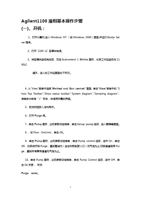
Agilent1100液相基本操作步骤(一)、开机:1、打开计算机,进入Windows NT (或Windows 2000)画面,并运行Bootp Server程序。
2、打开 1100 LC 各模块电源。
3、待各模块自检完成后,双击Instrument 1 Online图标,化学工作站自动与1100 LC通讯,进入的工作站画面如下所示。
4、从“View”菜单中选择“Method and Run control”画面, 单击”View”菜单中的“Show Top Toolbar”,“Show status toolbar”,“System diagram”,”Sampling diagram”,使其命令前有“√”标志,来调用所需的界面。
5、把流动相放入溶剂瓶中。
6、打开Purge阀。
7、单击Pump图标,出现参数设定菜单,单击Setup pump选项,进入泵编辑画面。
8 、设Flow:5ml/min,单击OK。
9、单击Pump图标,出现参数设定菜单,单击Pump control选项,选中On,单击OK,则系统开始Purge,直到管线内(由溶剂瓶到泵入口)无气泡为止,切换通道继续Purge,直到所有要用通道无气泡为止。
10、单击Pump图标,出现参数设定菜单,单击Pump Control选项,选中Off,单击Ok 关泵,关闭Purge valve。
11、单击Pump图标,出现参数设定菜单,单击Setup pump选项,进入Pump编辑画面,设Flow:1.0ml/min。
12、单击泵下面的瓶图标,如图所示(以二元泵为例),输入溶剂的实际体积和瓶体积。
也可输入停泵的体积。
单击Ok。
(二)数据采集方法编辑:1、开始编辑完整方法:●从“Method”菜单中选择“Edit entire method”项,如上图所示选中除“Data analysis”外的三项,单击Ok,进入下一画面。
2、方法信息:●在“Method Comments”中加入方法的信息(如:方法的用途等)。
安捷伦液相工作站操作
安捷伦液相工作站操作安捷伦(Agilent)液相工作站(LC workstations)是一种用于高效液相色谱(HPLC)操作的设备。
它提供了一个集成的系统,可用于样品准备、柱装载、方法开发和数据分析等各个方面。
以下是关于安捷伦液相工作站操作的详细说明,总字数超过1200字。
1.准备工作2.样品准备3.柱装载4.方法开发与优化5.数据采集与分析1.准备工作在开始使用液相工作站之前,需要进行准备工作以确保设备和耗材的正常运作。
首先,检查液相工作站的供电情况,确保电源接地良好。
然后,检查各个部件的接口连接是否紧固,并根据需要更换各种液相耗材,如进样针头、柱、连接管等。
此外,还需确认液相工作站是否已经经过了正确的校准和验证。
2.样品准备样品准备是液相工作站操作的关键步骤之一、首先,将待分析的样品进行准备,包括样品的稀释、过滤和提取等步骤,以确保样品处于适合分析的状态。
其次,根据样品的性质和分析要求,选择适当的进样方法。
常见的进样方法包括自动进样器和手动进样器,用户可以根据需要选择合适的进样方式。
在进行样品进样之前,还需要选择适当的固定相和流动相,以满足样品的分离要求。
3.柱装载柱装载是将柱和连通装置安装到液相工作站上的过程。
首先,选择适当的固定相和柱,然后将柱安装到液相工作站的柱槽上,并确保柱和连通装置之间的连接紧固可靠。
在进行柱装载之前,还需要确保柱和液相工作站的温度控制系统正常运作,并根据需要设置适当的柱温。
4.方法开发与优化方法开发与优化是为了实现样品的高效分离和准确分析。
在进行方法开发之前,需要进行一系列的优化步骤。
首先,根据样品的性质和分析要求,选择适当的分析模式,包括梯度洗脱、等温洗脱和等流速洗脱等。
然后,进行柱平衡和调整流速等步骤,以达到最佳的分离效果。
在进行方法开发的过程中,可以利用液相工作站的自动化功能,通过改变流速、梯度条件和柱温等参数,来寻找最佳的分析条件。
同时,还可以通过监测峰面积、保留时间和分辨率等指标来评估方法的优劣。
瓦里安最新工作站说明书

*此时已完成开机步骤,接下来就可以打开分析方法开始进样分析。
is 2.2 关机步骤
步骤 1 1. 将一个装有洗针溶剂的样品瓶放在自动进样器上,并记住摆放位置。
g 2. 执行原厂工程师所建立的清洗色谱柱及预柱的方法。 UnRe (AcquisitionàQuick Startà找出 Wash Column 的 method)
10
步骤 2 1. 建立新方法,请选择 FileàNew Method
tered 步骤 3 点击后出现下面窗口,此时需要选择该新方法属于哪一个仪器使用。 UnRegis 选好后点击”Next”继续。
11
步骤 4 1. 输入 方法名称 2. 输入 方法描述(可以不填写) 3. 按 OK 键继续
输入方法名称
13
步骤 8
red Misscellaneous:
1. Start mode:请选择 inject trigger on pumpA
te 2. End of Sequence:请选择 Leave pump on UnRegis 以上设定如无特别需要,建议不需要更改内容。
14
步骤 9
ed Pressure:保护系统及色谱柱的压力设定 r Min. Pressure :请设定 100psi te Max. pressure:请设定 4000psi
210 pump 设定结束。
is 步骤 10 1. 以下为 325 detector 的设定: UnReg (i) 点击 325 图标
15
Signal: Detector Bunch Rate、Noise Monitor Length、Response time: 定义为检测取样的点数及噪声监 控时间选取点数。 Detector Bunch Rate:建议设定为 2 (10Hz)。 Noise Monitor Length:建议设定为 64。 Response time:建议设定为 0.5。
瓦里安356-LC控制软件操作手册说明书
OPERATOR’S MANUALFORVarian 356-LCControl Software Polymer Laboratories Ltd, Now a part of Varian, Inc., Essex Road, Church Stretton,Shropshire SY6 6AX, UKTel +44 (0)1694 723581, Fax +44 (0)1694 722171, Service Tel +44 (0)1694 724333Polymer Laboratories, Varian, Inc., Amherst Fields Research Park, 160 Old FarmRoad,Amherst, MA 01002, USA Tel +1 413 253 9554, Fax +1 413 253 2476Polymer Laboratories, Varian B.V., Herculesweg 8, 4339 PL Middelburg,The Netherlands Tel +31 (0) 118 671500, Fax +31 (0)118 671502Polymer Laboratories, Varian Belgium NV SA, Mechelsesteenweg 362,2860 St.-Katelijne-Waver, Belgium Tel +32 (0) 15 556460, Fax +32 (0) 15 556186Polymer Laboratories, Varian Deutschland GmbH, Alsfelder Stra€e 6,D-64289 Darmstadt, Germany Tel: +49 (0) 6151 7030 Fax: +49 (0)6151 703237Varian S.A.,7 Avenue des Tropiques, Z.A. Courtaboeuf, B.P. 12F-91941 Les Ulis Cedex, France Tel +33 1.6986.3838 Fax: +33 1.6928.2308Please note that Varian, Inc. is now part of Agilent Technologies. For more information, go to /chem.CONTENTS1GENERAL INFORMATION3 1.1I NTRODUCTION (3)1.2S PECIFICATIONS (4)1.3C ONNECTING THE V ARIAN 356-LC TO A PC (5)1.3.1Use a Universal Serial Bus Interface (USB)51.3.2Adding an Extra Serial Card to your PC -Using Multiple Serial Ports5 1.4U SING S TAR W ORKSTATION WITH I NSTRUMENT C ONTROL S OFTWARE (5)1.5I NSTALLATION P ROCEDURES-S OFTWARE (7)1.5.1Installation of the PL Instrument Control Software from CD71.5.2Installation of the PL Instrument Control On-line Help from CD71.5.3Configuring the PL Instrument Control Software8 2THE GRAPHICAL USER INTERFACE10 2.1O VERVIEW (10)2.2S UMMARY V IEW (11)2.3C OMPONENT V IEW (11)2.4A UTOMATING THE V ARIAN 356-LC (12)3TROUBLESHOOTING14 3.1E RRORS (14)3.2V ARIAN 356-LC E RRORS (15)1General Information1.1IntroductionThe Varian 356-LC differential refractometer is a universal detector designed for high-performance analyses where the refractive index of a flowing liquid with respect to a reference is required. Its small cell volume, high sensitivity, and accurate temperature control make it well-suited for use as a detector in automated and manual high performance liquid chromatography.The Varian 356-LC RI detector can be operated as an integrated module within a Liquid Chromatography System using Galaxie™ Chromatography software. Alternatively, the detector can be used as a stand-alone HPLC detector through serial communications.This manual instructs the user how to install the PL Instrument Control software for operation of the Varian 356-LC RI as a stand-alone detector. For information on operating the detector please refer to the Operation manual.1.2SpecificationsRI range 1.0~1.75 RIURange 150-600x10-6/FS RIULinearity 600 ‚RIUSensitivity LOW (2), MED (4), HIGH (8) mV/‚RIUShort-term noise 1<5.0x10⁻⁹RIUDrift <2.5x10⁻⁷RIU/hourResponse time 0.1-5.0 secTemperature control OFF, 30-50 ƒC (1 ƒC increments)Cell volume 6 ‚LLight source LED 880 nmAnalogue output 1 V FSDDigital output24 bit (10 Hz) via serial portPolarity Positive/NegativeExternal communication RS232Autozero YESPurge YESFlow rate range0.1-10 mL/minPressure rating100 kPa (15 psi)Internal volume-inlet15 ‚LInternal volume-outlet459 ‚LTotal internal volume Normal operation 474 ‚LPurge mode 491 ‚LWetted material 316 SST, Quartz Glass, PTFE, PerfluoroelastomerPower requirements AC 100~240 V 50/60 HzPower consumption150 W (max)Dimensions (wxdxh)(unpacked)296 x 475 x 212 mmDimensions (packed)460 x 775 x 385 mmWeight (unpacked)11 kgWeight (packed)13.5 kgPC Requirements Windows…2000 & XPproRemote operation Remote purge & autozeroSafety features Error and leak detectionTable 1.Performance Specification of the Varian 356-LC RI Detector1According to ASTM method E-1303-95 “Practice for Refractive Index Detectors used in Liquid Chromatography”. Detector conditions; temperature 35 ƒ C, response time 4 sec.1.3Connecting the Varian 356-LC to a PC1.3.1PC RequirementsTo operate the Varian 356-LC detector using the Instrument Control Software, a free Serial (RS-232) communications port (1 to 255) is required on your PC. Mostcomputers are supplied with at least one serial port as standard, but if your PC does not provide a serial port, please see section 1.3.1.1& 1.3.1.2The Varian 356-LC Instrument Control Software is only compatible with Windows…2000 & XP Pro.1.3.1.1Use a Universal Serial Bus (USB)to Serial InterfaceIf your PC has one or more Universal Serial Bus (USB) connectors then you can use a “USB –Serial Port Adaptor” (part # 0860-0620), which provides a Serial Port connection to your PC. The Universal Serial Bus interface is supported on:④ Windows 98④ Windows ME④ Windows 2000④ Windows XPUSB is NOT Supported on NT 4.0. You may require extra software to use USB on Windows1.3.1.2Adding an Extra Serial Card to your PC -Using Multiple Serial Ports Multiple Port Serial cards are available, which allow 4, 8 and 16 extra serial ports to be added to your PC using a single PCI card.1.3.2Serial ConnectionEnsure that the Varian 356-LC detector is switched on and operating normally. Make sure you have one free and valid RS-232 communications port (1 to 255).Connect the serial port on your PC to the port labelled "RS232" on the rear of the detector, using the serial cable provided. Ensure that the flash upgrade switch, (see figure 1) is located in the RUN position (i.e. downwards).1.4Instrument Control for non-Galaxie UsersThe Varian 356-LC was designed to integrate fully into Galaxie Chromatography software, allowing the user to control the instrument,remotely for unattendedoperation.However, for non-Galaxie users (e.g. Star or MS workstation)the Varian 356-LC Control software (v2.2), provides a standalone control of the Varian 356-LC NOTE !The 356-LC Instrument Control software provides direct control of the Varian 356-LC, via the RS232 port, in much the same way as front panel control. It does not provide data acquisition.For data acquisition and control, the Control software must be used in conjunction with a chromatographic data acquisition package,such as Star or MS Workstation. The Varian 356-LC’s analogue data can be collected by connecting the supplied analogue output cable (Part No. PL0880-0310) from the rear of the detector (see figure 1) to an A/D interface (e.g.Star MIB 800 module). Please refer to the Star or MS workstation user manual for more information on how to configure the Star 800 modules.Figure 1. Rear view of the Varian 356-LC RI Detector1.Serial RS232 connector –24 bit digital output2.Control firmware flash upgrade switch3.Connector control I/O –15 pin D type female4.Analogue output -‰1 V5.Mains switch6.Mains input1235461.5Installation Procedures-Software1.5.1Installation of the PL Instrument Control Software from CDPlace the CD-ROM containing the Varian 356-LC Control software into the CD drive. In most cases the CD browser window will automatically open. However if the window does not appear then select the Run option in the Start menu, and type in D:\launch.exe (where D: denotes the CD drive).From the CD browser window select the Install the Software option and follow the on-screen instructions, it is recommended that the default settings are selected.Ensure that when you log on to the PCyou have full administration rights.You may need to restart your computer at the end of installation; if this is required you will be prompted to do so.After successful installation of the Control software, the program is simply run by clicking on the application named PL Instrument Control (PLInstControl.exe) installed in the PL Instrument Control group of the Programs option in the Start menu.The default location for the program files will be C:\Program Files\Polymer Laboratories\PL Instrument Control, which contains the following files:-Before running the program thesoftware must be first configured,see section 1.5.3.1.5.2Installation of the Instrument Control On-line Help from CDFrom the CD browser window select the Install Online Help option and follow the on-screen instructions, it is recommended that the default settings are selected. Thetwo help files (one for the PL Instrument Control software and the other for the PL Instrument Configuration Editor program) will be installed and the default location will be C:\Program Files\Polymer Laboratories\PL Instrument Control\Docs.1.5.3Configuring the Instrument Control SoftwareThe Control Software needs to be closed down before startingthis program.The configuration of the Varian 356-LC should normally be doneby a qualified Varian representative.To configure the Control software for the Varian 356-LC, you need to run the PL Instrument Configuration Editor to define the components that make up the instrument. The PL Instrument Configuration Editor is simply run by clicking on the application named PL Instrument Configuration Editor (PLInstConfigEd.exe) installed in the Service group of the PL Instrument Control group of the Programs option in the Start menu.The first time the PL Configuration Editor program is run, theprogram displays all the components that are available forcontrol.For the initial configuration of the system select the Varian 356-LC from the list by left clicking on the name of the component so that the configuration matches the instrument.Once the Varian 356-LC configuration has been completed the correct Com port needs to be assigned. To set the Com port, double click on the component name. The Configure Component dialog will open, where the correct Com port can be entered.Once the Com ports is set correctly, close the configuration editor and wait while the new configuration is saved. While the new configuration is being saved the following message will be displayed: -Updating the instrument configuration cantake up to a minute so please bepatience.For further information on configuring a system then please see the on-line help within the PL Configuration Editor program.Chapter 2-The Graphical User Interface2The Graphical User InterfaceTotal instrument control of the Varian 356-LC is provided by a Windows-based Graphical User Interface (GUI). This intuitive interface provides simplistic control as well as a comprehensive monitoring system.For further information on the PL Instrument Controlsoftware please see the on-line help within theprogram.To start the 356-LC Control software, select the PL Instrument Control item in the PL Instrument Control program group of the Programs option in the Start menu. 2.1OverviewThe Control screen is effectively divided into two main Views, these are:1.The Summary View2.The Component View2.2Summary ViewThe summary view displays the status of the Varian356-LC and a quick way of accessing the various parameters and options available within the PL Instrument Control software.A green LED next to the Varian 356-LC name indicates the module is being controlled and running whereas a red LED would indicate the module is either not running or not controlled.For further information on the Summary View please see the on-line help within the PL Instrument Control software.2.3Component ViewThe component view provides direct access to the Varian 356-LC control parameters. In general each component view contains a number of common items and options. The actual items available in a view are dependent on the component selected.The general component view for all components except for autosamplers/carousels is shown below.Status Bar–This displays Varian 356-LC description and current status.On-line Help Button–This is a direct link to the on-line help for that component view. Parameter Grid–This displays the current set parameter(s) for the 356-LC. To set and update the parameter(s) enter the required value(s) in the Set Value column and press the UPDATE button.To undo any parameter(s) prior to pressing the Update button press the Undo button,.To reset the parameter(s) back to the default value(s) press the Factory Reset button, .Help Output Window–This displays a simple summary help for each parameter and action. To view this information, select the parameter or action. The information displayed in the Help Window will be a short description about the action or parameter, the Factory Default Value and the Minimum and Maximum Values for the parameter.Action Button(s)–The Varian 356-LC can be Purged or Autozeroed using the Action Buttons, as well as from the Action List. To run an action, press the required Action button.Press the STOP button, to stop all the procedures currently running on the selected component.For information on the Toolbar menus please see the on-line help within the PL Instrument Control software.2.4Automating the Varian 356-LCThe Instrument Control software provides the ability to automate the control of the Varian 356-LC using the Events Schedule Editor. To open the Events Schedule Editor and create a schedule, select the Edit Schedule option from the Automation menu on the toolbar. The editor will initially display a default Events Schedule consisting of a single Process and Sequence entry. This ensures you only have to add a Procedure entry for the schedule to be valid.To add a Procedure right click on the Sequence entry in the schedule, the Procedure Details window will open where the required action can be selected.Once the Events Schedule is completed press the Start button, to start the schedule.The schedule can be used to equilibrate the detector by automatically purging a autozeroing the detector.Message boxes can be displayed at key stages during an Event Schedule. These message boxes require user input before the rest of the schedule can be run. The text displayed in the message box is customisable allowing simple status information or more detailed instructions to be displayed to the operator. Two examples of this are: -∙ Providing a simple guide path to an operator for the manual operation of the system.∙ Providing feedback / key information to an operator at key stages of a more automated system.For further information on the Event Schedule Editor please see the on-line help within the Instrument Control software.3Troubleshooting3.1ErrorsAny error(s) that occur with communications or operations (running component actions, updating parameters etc.) with the instrument, the Diagnostic Output Window will automatically open with the error(s) displayed in the Component Error Status Tab of the Diagnostic Output Window as shown below. Each error is uniquely identified with a number that can be referenced back to the control code.Figure 2.Diagnostic Output WindowNote:The information displayed in last two Tabs is primarily for service diagnostics and the Window does not need to be open for normal operation of the instrument.If an error is displayed it needs to be cleared in order for the diagnostic window to be closed, allowing access back to the PL Instrument Control software. To clear an error press the Select button to highlight the row and press the Clear button. Multiple errors can be selected at a time. Once all errors have been cleared the diagnostic window can be closed.Clearing an error will stop all procedures that are running and attempting to communicate with the component. To re-establish communications with the component either select the Reconnect option from the Instrument menu or return to the component view and resend the parameters or repeat the required action.The errors that can be displayed from the software are listed on the following pages.3.2Varian 356-LC ErrorsGeneral System ErrorsError Cause(s)ActionCould not initialise specified comms port Incorrect Com portassigned to thecomponent, the PL-GPC50 Plus is not poweredon or the USB cable isnot connected.Ensure the correct Com port has beenassigned within the PL InstrumentConfiguration Editor program. Ensurethe PL-GPC 50 Plus is powered on andthe USB cable is connected.No response received from the device Incorrect Com portassigned to thecomponent orcommunications lost withthe component, e.g.power failure.Ensure the correct Com port has beenassigned within the PL InstrumentConfiguration Editor program. Ensurethe PL-GPC 50 Plus and/or componentis powered on. If assigned Com port iscorrect and the system is powered onthen contact Polymer Laboratories oryour local agent.Unrecognised response from the device Turn the PL-GPC 50 Plus off and then on again (ensure the control software has been closed before turning the instrument off). If this error persists then contact Polymer Laboratories or your local agent.The device rejected the last command Incorrect componentassigned to the Comport.Ensure the correct component hasbeen assigned to the correct Com portwithin the PL Instrument ConfigurationEditor program.The device returned an error The component failed tocomplete an action.Reinitialise the component from the PLInstrument Control software and ensurethe initialisation is completedsuccessfully. Otherwise turn the PL-GPC 50 Plus off and then on again(ensure the control software has beenclosed before turning the instrumentoff). If unsuccessful and no obviouscause for the error then contactPolymer Laboratories or your localagent.Instrument ErrorsError Cause(s)Action01Fan stopped/failed Fault with the circuitry/wires/fan. Callyour Varian customer supportrepresentative if this happens regularly.02Upper leak detectorthermistor failure.Liquid sensor needs replacing. Call your Varian customer supportrepresentative.03Lower leak detectorthermistor failure.Liquid sensor needs replacing. Call your Varian customer supportrepresentative.04Internal vapour sensorfailure.Vapour sensor needs replacing. Call your Varian customer supportrepresentative.05External vapour sensorfailure.Vapour sensor needs replacing. Call your Varian customer supportrepresentative.06Liquid leak sensor hasdetected liquid in driptray.Liquid in the base of the unit -Stop pump and investigate.07High concentration ofvapour detected outsideof unit.Ensure sufficient ventilation around themodule.Check for a solvent leak.08Heated block thermistorbelow minimumthreshold.Call your Varian customer supportrepresentative.09Heated block thermistorabove maximumthreshold.Call your Varian customer supportrepresentative.0A Light source error Replace the light source assembly. Callyour Varian customer supportrepresentative.Auto-Zero (01)Autozero timeout Re-autozero the detector.。
安捷伦A操作规程
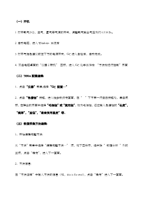
(一)开机1 打开载气(N2),空气,氢气等气源的开关,调整载气输出气压为约0.5 M Pa。
2 启动电脑,进入Windows 系统后3 打开气相色谱仪前左下方的电源开关,GC进入自检后,启动完成。
4. 双击电脑桌面的“仪器2联机”图标,进入GC化学工作站“方法和运行控制”界面(二)7890A配置编辑:1.点击“仪器”菜单,选择“GC 配置…”2.点击“色谱柱”按钮,进入柱参数设定画面,在“”下方第一行空白按钮处,单击鼠标,在弹出的界面中选择“毛细柱”或“填充柱”,如为毛细柱,还应输入色谱柱的“长度”,“模厚”,“直径”,“最高使用温度”等。
(三)数据采集方法编辑:1、开始编辑完整方法:从“方法”菜单中选择“编辑完整方法…”项,如下图所示,选中除“数据分析”外的三项,点击“确定”,进入下一画面。
2、方法信息:在“方法注释”中输入方法的信息(如,this is for test!),点击“确定”进入下一画面。
3、进样器设置:在“选择进样源/位置”画面中选择“GC 进样器”,并选择所用的进样口的物理位置(前或后)。
点击“确定”,进入下一画面。
4、柱模式(CFT)设定:点击“”图标,进入柱模式设定画面,选择控制模式,“流速”或“压力”。
如:压力,25 psi;或流速,6.5ml/min。
5、分流不分流进样口参数设定:点击“”图标,进入进样口设定画面。
点击“模式”右方的下拉式箭头,选择进样方式为“不分流”(或分流方式,分流)。
输入进样口的温度(如250℃),输入隔垫吹扫流量(如3ml/min)。
在“分流出口吹扫流量”下边的空白框内输入吹扫流量(如0.75min 后60ml/min); 如选择分流方式, 则要输入“分流比”。
6、柱温箱温度参数设定:点击“”图标,进入柱温参数设定。
在空白表框内输入温度,选中“柱温箱温度为开”左边的方框;℃/min—升温速率;输入合适的升温参数。
7、FID检测器参数设定:点击“”图标,进入检测器参数设定。
Agilent 化学工作站操作说明

Agilent 化学工作站操作说明目录第一章 工作站和色谱仪的开启 (1)第二章 编辑分析方法 (2)第三章 运行方法 (31)第四章 数据分析 (33)第五章 校正设置 (39)第六章 工作站的配置 (47)一、工作站和色谱仪的开启1.1 检查色谱仪主机的所有气源是否连接好、所有气体是否打开并进行试漏。
1.2 确保上述情况完好,开色谱仪主机电源并等待通过自检。
开计算机电源。
图1:工作站开启界面1.3 在计算机屏幕上单击Start选择Programs再选择ChemStations双击Instrument 1 Online.等待GC与工作站的连接出现初始状态。
如有第二通道则有Instrument 2 Online 存在。
图2:工作站开启图标1.4 也可在计算机屏幕上双击图标。
1.5 Instrument 1 Online为连接GC状态、Instrument 1 Offline为脱离GC状态。
先开Instrument 1 Online可继续打开Instrument 1 Offline、先开Instrument1 Offline不能继续打开Instrument 1 Online。
1.6 注意:在Instrument 1 Offline状态下改动分析方法如果存储则Instrument 1Online下的方法也将改动。
1.7 本操作说明均指在Instrument 1 Online状态并安装EPC。
二、编辑分析方法在这只对仪器控制和数据采集参数进行说明,数据分析处理将在后面说明。
图3 显示菜单2.1 此菜单提供显示的画面,前三项与选择是方法和运行控制界面、数据分析界面还是报告设计界面相同,Show Top Toolbar为快捷方式工具栏(本界面最上的图标一栏),Show Status Toolbar为仪器状态栏(本界面第二图标栏),其他经常使用的为在线信号(Online Signals)1或2和仪器状态(Instrument Actuals)及化学工作站状态(Chemstation Status)。
安捷伦操作手册

提问汇总:1.GC静态顶空能做农产品或水质中痕量物质检测吗?2.PE顶空原理是什么?怎么只有注射器和定量环?3.用静态顶空测定有机残留溶剂,如苯系列化合物,如果用FID,能检测到大致多少限量呢?4.顶空进样的参数优化问题能否举几个例子详细讲解下5.在静态顶空进样过程中,样品瓶需要一直放在水浴中不拿出吗?一旦样品瓶凉了,是不是结果就不准确了?如果不是密封针,会不会在吸取顶空气的时候吸入空气啊?6.顶空进样可以分几种?有静态顶空,是不是还有动态的?7.顶空进样的检测灵敏度跟哪些因素有关系呀?8.顶空技术的最大优势是什么?9.传输线的温度和组分沸点的关系什么?10.我现在用顶空做二氧化硫的检测,现在除了重复性差之外线性也不好,(色谱柱DB-624,检测器FPD,亚硫酸钠与盐酸反应生成的二氧化硫)请问我现在应该从哪些方面排查问题呢?11.顶空技术应该进的是气体样品,那么,应该进多大体积呢?顶空技术进样和液体进样有什么不同?农药残留检测可以用在顶空技术上么?12.顶空技术中所谓的气液平衡,液体是什么液体,是有机溶剂吗?还是别的?13.我觉得这项技术比较适合易挥发物质的检测,相溶于溶液中的物质是不检测不了,局限性还是挺大的,不知道我说的对不对?14.这项技术对色谱仪有没有特殊的要求?15.在现有的仪器上加装顶空进样系统有什么难点或者需要注意的地方?16.DMF在100度恒温20分钟,会不会分解产生杂质?我们用PE顶空,最近发现采用DMF作为溶剂,在100度恒温20分钟进样,柱温40度,用DB-624的柱子,在5分钟左右总是有一个小杂质峰。
空气和水作为溶剂就没有。
17.我们常用水,DMF,DMSO作为溶剂,有的文献采用二甲基乙酰胺,不知道老师用过没有,能不能介绍一下二甲基乙酰胺作为顶空系统的溶剂使用时,有哪些优点。
18.顶空时样器如果长时间用脏了怎么办?曾经有过这样的例子,无论进什么溶剂都会有很多杂质峰出来,如果用手动进样的话就没有,后来把顶空所有的管路都取下来用高压锅煮,煮了半天拿出来重新安装效果比原来好多了,但这可操作性太差了,不是人人都能做的,请问有没有可操作性强,而且省力的好方法呢?19.我用的PE的顶空仪器,检测液体样品的话,一般取样量多少质量或体积?因为对于含有很多有机物的液体来说,即使进几十微升的量也可能出现检测器饱和的问题。
安捷伦液相色谱系统化学工作站站安装与卸载B版软件
安捷伦气相色谱系统化学工作站安装与卸载:(本方法适用于B.01.01C/B.02.01SR1/B.03.01SR1 版安捷伦气相化学工作站安装与卸载,本方法仅供你们使用,请勿向外传播,谢谢!祝一切顺利!!)卸载化学工作站有时,可能需要卸载化学工作站(例如,化学工作站出了问题,或要在其他位置安装该软件)。
要完全删除化学工作站安装,您可以使用标准Windows 卸载程序(“控制面板”→“添加/ 删除程序”)。
要进行卸载,请执行以下步骤:1 如果化学工作站正在运行,请关闭所有会话并重新引导计算机。
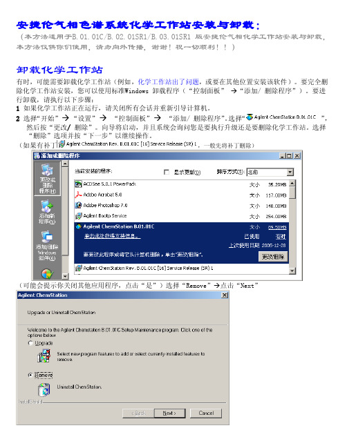
2 选择“开始”→“设置”→“控制面板”→“添加/ 删除程序”。
选择“”,然后按“更改/ 删除”。
向导将启动,并且系统会询问您是要执行升级还是要删除化学工作站。
选择“删除”选项并按“下一步”以继续操作。
(如果有补丁,一般先将补丁删除)(可能会提示你关闭其他应用程序,点击“是”)选择“Remove”→点击“Next”2开始卸载之前,系统将在继续操作之前提示您确认卸载。
单击“是”以继续操作。
4 在卸载过程中,系统将备份化学工作站数据、方法、序列、UV 库和自定义报告类型,以及所有自定义宏(例如user.mac)(如果有)。
系统将创建一个目录(例如,名为c:\Chem32_Backup)来存储数据。
数据的原始结构将保留,例如:• \CHEM32_Backup\1\• \CHEM32_Backup\2\• \CHEM32_Backup\3\• \CHEM32_Backup\4\包含仪器1 至4 的所有数据、方法、序列和超级序列软件• \CHEM32_Backup\REPSTYLE 包含自定义的报告• \CHEM32_Backup\CORE 包含最终的自定义宏user.mac5 完整的CHEM32 文件夹将从硬盘上被删除。
6 化学工作站路径声明将从Windows 操作系统环境中的环境路径变量中被删除。
删除完毕,重新启动计算机后,即可重新安装安捷伦化学工作站了。
- 1、下载文档前请自行甄别文档内容的完整性,平台不提供额外的编辑、内容补充、找答案等附加服务。
- 2、"仅部分预览"的文档,不可在线预览部分如存在完整性等问题,可反馈申请退款(可完整预览的文档不适用该条件!)。
- 3、如文档侵犯您的权益,请联系客服反馈,我们会尽快为您处理(人工客服工作时间:9:00-18:30)。
安捷伦和瓦里安工作站操作手册
安捷伦
1激活安捷伦工作站的导出功能
以安捷伦主目录安装在C盘根目录为例:
第一步:备份win.ini(c:\windows)或者/chemstation.ine(c:\windows)
第二步:XML功能的启用需要按照下面的设置修改初始化文件:
对于A版化学工作站,需要修改win.ini(C:\WINDOWS)
对于B版化学工作站,需要修改Chemstation.ini(C:\WINDOWS)
需要在以上两个文件中的[PCS]部分添加以下内容:
[PCS]
XMLEnableImport=1
XMLEnableExport=1
添加完成后,重新进入化学工作站中将会看到“识别峰,计算结果并将结果文件上载到远程服务器”该功能被激活。
第三步:与导入相关的录入项
与导入相关的录入项是仪器专用的,并且设置在chemstation.ini/win.ini文件的[PCS,n] 部分(其中n 为仪器编号)。
指定缺省导入目录
以下录入项指定要导入的文件所在的缺省目录。
[PCS,n]
XMLImportPath$=d:\xml\wrkl\
【注:在D盘建立xml文件夹,并在其中建立wrkl文件夹】
第四步:与导出相关的录入项
与导出相关的录入项可以是系统级的(设置在chemstation.ini文件的[PCS]部分),也可以是仪器专用的(设置在chemstation.ini文件的[PCS,n]部分,其中n为仪器编号)。
启用自动模式
在自动模式下,系统会在序列运行时自动将XML 结果文件从本地原始数据文件目录复制到的远程位置。
[PCS]
XMLAutomation=1
第五步:设置超时条件
以下录入项指定复制结果文件至远程位置的尝试次数以及每次尝试之间的等待时间(以秒为单位)。
[PCS]
XMLExportCopyWaitTime=3
XMLExportCopyTries=10
第六步:指定恢复路径
如果复制过程在尝试指定的次数(请参阅上文)之后失败,以下录入项会指定保存XML 文件的恢复目录。
该目录必须是本地目录。
[PCS]
XMLExportLocalRecovPath$=c:\Chem32\recovery\
【注:在Chem32文件夹下建立recovery文件夹】
第七步:设置缺省导出路径
以下录入项指定启用“自动”(请参阅上文)时文件导出到的缺省远程路径。
[PCS,n]
2数据自动导出
第一步:将安捷伦中的分析方法按照Samplemanager里面的分析方法来重新命名;
第二步:调用相应的分析方法来处理谱图;
第三步:将谱图处理完毕以后,再次确认Sample ID是否正确;
第四步:切换到“数据处理”页面,此时点击已激活的“识别峰,计算结果并将结果文件上载到远程服务器”按钮,即可将数据自动导出到LIMS服务器。
瓦里安CP3800
1文本文件的形成
谱图处理完毕后,可以看到报告的界面,点击工具栏的“文件”按钮,在其下拉菜单中单击“转换ASCⅡ码”,此时在数据文件夹DATA下面会生成一个报告模式的文本文件;
2文本文件的导出设置
通过批处理的方式将文本文件导出
第一步:在数据文件的根目录建立一个文本文件,将其命名为Auto1(2、3),格式修改为“.bat”;
第二步:用记事本打开该文件,在其中写入如下内容(注意空格);
Xcopy .\*.txt /Q/S \\10.112.211.31\CP3800\
Del .\*.txt /Q/S 【见下图】
第三步:将已建好的批处理文件的快捷方式发送至桌面。
3文本文件的导出
第一步:通过点击报告界面工具栏的“文件”,在其下拉菜单中选择“转换ASCⅡ码”;
第二步:修改导出文本文件的名称为“样品号”;
第三步:双击桌面上相应的批处理文件的快捷方式,数据即导出。