YD2512直流低阻说明书
汽车充电机及DCDC测试内容
JLxxx
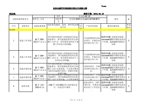
长沙众泰汽车供应商自我认可试验大纲
注1:完成供应商认可试验大纲是签订试验计划的必要条件之一。
2:表格中供应商的测试仪器/设备一栏中所填写的内容须与《长沙众泰汽车供应商自我认可
试验能力报审表》对应,而且其功能/精度应满足标准的要求。
供应商自我试验室及仪器/设备经长沙众泰汽车产品认可部门确认后,其资源将列入长沙众泰
汽车可合作的试验室数据库中,供应商将承诺长沙众泰汽车有其资源共享的权利。
3:表格中测试方法一栏中所填写的内容应该是在满足标准条件下,结合供应商测试设备操
作程序的试验方法。
第 11 页,共 11 页。
大毅2512合金低温漂采样电阻RLM25系列选型手册

pull 300 mm/min standard: 0.1 ~ 0.7 N
12. Storage Conditions:
Temperature: 5℃~35℃,Humidity:40%~75%
13. Shelf Life:
2 years from manufacturing date.
TA-I TECHNOLOGY CO., LTD
www.jepsun.com
Document No
TRLM-250S149C 2015/11/24 4/6
Lead-Free Current Sensing Resistors RLM Series ( Halogen-Free )
Issued date Page
7. Number of Package: 4000 Pieces / package
2. Type Designation:
RLM Item 25 Series No. 25:2512 (6432) F Resistance tolerance F:±1% G:±2% J:±5% E Packaging C Power rating C=1W D=1.5W E=2W R010 Resistance
Iron Solder:350±10℃ , 3+1/-0 sec
℃ , 5 sec
15. ECN
Engineering Change Notice: The customer will be informed with ECN if there is significant modification on the characteristics and materials described in Approval Sheet.
TH2511直流低电阻测试仪使用说明书
3.上极限设定: 按下上极限置限按钮,仪器显示当前上 限值,调节上限置限电位器至所需电阻值。
4.下极限设定:按下下极限置限按钮,仪器显示当前下 限值,调节下限置限电位器至所需电阻值。
5.按下测量按钮,由置限状态返回到测量状态。 6.分选结果指示
1
AB
R
D+
D-
S+
S-
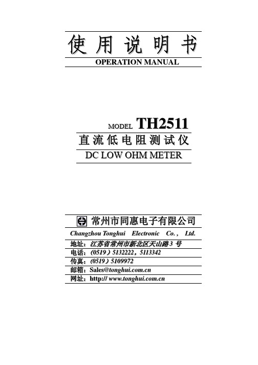
6.4.2 错误的测试连接方法。如果采用下图的连接方法测 试。测试结果包含了 S+、S-端至 A、B 端的引线电阻。当被 测标准电阻值很小时,将引入较大的误差。
DS-
D+ S+
6.4.3 正确的连接方法如下图所示,采用四端分开的测试线, 以便消除标准电阻引线的误差。
5
TH2511 型直流低电阻测试仪
当测量值>上限时,上超灯(OVER)亮. 当测量值<下限时,下超灯(DOWN)亮. 当下限<测量值<上限时,合格灯(PASS)亮. 当合格灯亮的同时,蜂鸣器响.(蜂鸣器可由后面板上 的开关控制)
3. 工作原理 恒流源产生稳恒电流加到被测电阻 Rx 上,产生电压降 Ux;稳恒电流同时加到基准电阻 Rs 上,产生电压降 Us。 Ux 和 Us 经放大器放大后分别连接到 A/D 转换器的测量端 和基准端,A/D 转换结果送显示器显示。
2. 技术参数 2.1 本仪器采用 4 位半数码管显示,最小分辨率为:10μΩ。
当被测电阻超出量程范围时,显示器闪烁,提醒操作者 切换量程。 2.2 测量范围
10μΩ - 1.9999kΩ分五个量程 量程 1 : 10μΩ - 199.99mΩ 量程 2 : 100μΩ - 1.9999Ω 量程 3 : 1mΩ - 19.999Ω 量程 4 : 10mΩ - 199.99Ω 量程 5 : 100mΩ - 1.9999kΩ 2.3 测量误差 2.3.1 工作误差 在环境温度为 20℃±5℃的条件下 量程 1、2 误差为: ±0.2%读数值±4 个字 量程 3、4、5 误差为: ±0.2%读数值±2 个字 2.3.2 温度系数 环境温度在 0℃~15℃或 25℃~40℃的条件下, 由 于温度变化而引的起误差为: (±0.003%读数值±1 字)/℃。
KD2531T2说明书

使用说明书KD2531T2等电位连接电阻测量仪武汉市康达电气有限公司目录1 性能特点 (1)2 技术指标 (2)2.1 主要指标 (2)2.2 其它指标 (2)3 仪表外形 (3)4 使用方法 (4)4.1 电池 (4)4.1.1 电池配置 (4)4.1.2 电量检查 (4)4.2. 锂电池充电和拆装 (4)4.3 电阻测量 (5)5 注意事项 (6)6 附件 (6)7 常见现象及说明 (7)尊敬的用户:欢迎您使用KD2531T2等电位连接电阻测量仪。
为保障您的安全和仪表正常使用,请先仔细读完本说明书再进行操作。
本仪器安全性能符合国际标准IEC61010-1:2001。
本仪器执行标准Q/WKD07,符合GB/T 21431-2008 建筑物防雷装置检测技术规范1 性能特点●适于测量等电位连接电阻、各种电气设备间连接导体的电阻。
也可以测量开关、插座触点的接触电阻以及其它低值电阻。
●采用“四端子”测试技术,消除引线电阻引起的测量误差。
●采用数字微处理器,示值准确精度高,稳定可靠。
●3 1/2LCD大屏幕数字显示,并带有背光及读数锁定功能。
●有二种工作模式,短定时4秒钟和长定时5小时,当定时时间到后自动锁定读数、停止测试,并伴有声光提示。
●内置11.1V/1.8Ah锂电池供电,可连续工作约8小时。
●电池符号“”显示电量,并具备电池欠压报警功能。
●电流测试极开路时有开路指示符“OPEN”指示。
●操作简单,携带方便。
●具有防震、防尘、防潮结构,适应恶劣工作环境。
2 技术指标2.1 主要指标2.2 其它指标●绝缘电阻:500V ≥20MΩ●耐压:AC 1.5kV 50Hz 1min●工作温度和湿度:-10℃~+50℃≤85%RH●贮存温度和湿度:-15℃~+55℃≤90%RH●电源:8×1.5V(AA,LR6) 电池或11.1V/1.8Ah锂电池耗电:≤180mA●外形尺寸:255mm(L)×135mm(W)×80mm(D)●重量:≈0.8kg注:此说明书所述技术指标仅适于您现用的仪表,本公司保留对其变更的权力。
2512 0.027R 贴片电阻_顺海科技
2512 0.027R 贴片电阻贴片电阻指的是电阻的一种生产与使用的方式,贴片电阻最开始是有插件色环电阻与玻璃釉电阻,金属膜电阻,炭膜电阻等以插件形式的为主,随着便携式产品不断发展,以及人们对电子产品的需求不断增加的情况下,是机械化生产的一次重大进步,除了贴片电阻以外,其他的元器件均转型成功,如贴片电容,贴片电感,贴片二三极管等等。
下面介绍下 2512 0.027R 贴片电阻有哪些特点与型号参数:2512 0.027R 贴片电阻在电路中主要起到采样电流的作用,因此也被称为采样电阻,因为单位为毫欧(mR),因此也被称为毫欧电阻。
2512 0.027R 贴片电阻,下面列举下参数与材质:2512 0.027R 3W 1% 50ppm/℃,铁铬铝合金,康铜合金,镍铬合金,镍铜合金等。
2512 0.027R 2W 1% 50ppm/℃,陶瓷合金,铁铬铝合金,康铜合金,镍铬合金,镍铜合金等。
1225 0.027R 3W 1% 50ppm/℃,锰铜陶瓷合金(1225 长电极合金电阻)2512 0.027R 2W 1% 75ppm/℃,金属膜贴片电阻2512 0.027R 2W 1% 600ppm/℃,厚膜升功率贴片电阻2512 0.027R 1W 1% 600ppm/℃,厚膜贴片电阻因为2512 0.027R 贴片电阻基本上都是应用在采样电路,因此对电阻的精度与可靠性要求极高,所以大部分均为1%或者更高精度,但是有部分产品对采样电阻的宽度较大和节约成本,因此有会有很多选择5%精度的。
5%精度的基本上都是属于厚膜普通贴片电阻,参数如下:2512 0.027R 2W 5% 600ppm/℃,厚膜升功率贴片电阻2512 0.027R 1W 5% 600ppm/℃,厚膜贴片电阻。
ZC2512A直流低电阻测试仪说明书

ZC2512/A/B 智能低电阻测试仪专用于测试各种电阻。ZC2512 可 测量从 1uΩ到 2MΩ范围内电阻,ZC2512A 可测量从 10uΩ到 200kΩ范 围内电阻,ZC2512B 可测量从 1uΩ到 20kΩ范围内电阻。
本机另外附加分选功能。在分选状态时,可选择显示电阻值或百 分比值,且可依设定值判断电阻值的太大,太小或为良品。在仪器后 面板同时有分选接口,使能该接口启动信号,使仪器进行测量,测试 结果同时由后面板该接口输出,通过此信号接口使本仪器可接于元件 机械处理设备而进行自动测试。
测试中应注意的几个问题
ZC2512/A/B 使用说明书
1. 开机预热:测试前必须开机预热 10 分钟以上,以等待仪器内部线 路电参数稳定后再进行测试。 2. 零点及清零:当使用 20mΩ和 200mΩ两量程时,应首先清零再进 行测试,而在其它量程一般不必清零。测试时,使用者可先选定量程, 再把测试夹互夹,使 S+端与 S-端直接接触,D+端与 D-端直接接触, 并保持良好接触,如若仪器显示不为零时,请按前面板清零键,则清 零 ON 指示灯亮,仪器清零。
直至符合需要。再按下设置键,仪器会退出设置状态,结束设置。
c.此时,用户就可以根据所设置的值进行分选了。
七. 接口信号说明(Handler)
Handler 接口信号为一个 D 型 9 PIN 的连接器选购配备,其信号定义如
下表:
PIN 信号名称
定义
1
LOW
下超差信号(小于下限)
2
HIGH
上超差信号(大于下限)
另外,本机亦有 GPIB(IEEE-488)接口(选件),面板功能可完 全由电脑控制,测试结果亦可通过 GPIB 送回电脑保存。 本机有如下特点: 1. 电阻测试范围宽:
JK2512 系列型智能直流低电阻测度仪使用说明书
MODEL2512B系列智能直流低电阻测度仪操作使用手册常州市金艾联电子科技有限公司TEL:*************89187775概述JK2512B智能直流低电阻测试仪的外观流畅简洁,操作简便直观。
以新颖的设计思路,让各类触及者拥有全新的感觉。
特点介绍1直观的显示使用液晶显示,使得各项参数的显示都有明确的提示,也不管白天黑夜,都有清晰的字符让您一目了然,更没有让人眼花缭乱的各种指示灯让您难以记忆。
2少量的按键本仪器仅有四个操作按键,让您无须记忆更多条条款款,设置更多的功能数据。
3多参数显示当您读出了电阻值将其换算成百分比误差而感到麻烦,当您读出了百分比误差而将仪器显示改为显示电阻时感到重复工作时,您不妨选择本仪器的分选功能吧。
本仪器在分选测量时既显示电阻值,又显示百分比误差;在直读测量时既显示电阻值,又显示测量量程和读数范围,方便了您的阅读。
并且在设置时显示文字告知您正在做什么。
4等级品讯示在生产线上您也许要将电阻分成三个精度级别,本仪器完全可以满足您的要求。
本仪器可以按百分比的形式设置为三个等级品。
有合格闪光提示和合格的级别显示,也有合格讯响,但您可以关掉讯响而仅有合格灯指示和级别显示。
5通信接口如果您需要自动化测量,您可以利用通信接口达到这一目的。
本仪器的接口设计充分考虑了用户的方便性,您只要根据说明书对您的“编程器”或“计算机”简单编程,也可以用简单的硬件电路就可轻松完成。
6方便的校准如果为了校准要打开仪器机箱是一件多么麻烦的事情,如果为了校准要调节电位器是一件多么古老的方法。
本仪器的一种新的校准方法——人机对话的标准方式,只要按按键盘即可完成校准。
手册目录章节目录次目录页次第一章测试中注意事项4第二章安全规定4第三章安装要点5第四章技术规范6第五章面板和背板7面板图7面板说明7背板说明8第六章中英文词语对照表9第七章测试参数设定程序10第八章操作程序及步骤13第九章校准程序和步骤15JK2512B型智能直流低电阻测试仪使用说明书第一章:测试中的注意事项1开机预热仪器开机测试前必须预热15分钟,以等待仪器内部线路电参数稳定后再测量。
YD2511A说明书
目录一、概述 (2)二、性能特点 (2)三、面板功能说明 (4)四、后面板功能说明 (6)五、操作步骤说明 (7)六、成套与保修 (9)一、概述2511A型智能直流多电阻测试仪能对变压器、电机、开关、继电器、接插件等各类电阻进行测试,仪器测量范围1uΩ~2M Ω,仪器产生高精度恒流经被测件进行四端点测量,有效地扣除了引线误差,适合用户作高精度测量;由于使用直流测试及最多可以进行10组负载的快速扫描测试,对各类变压器及电感的铜阻测量尤为适合;本仪器扩展了同类仪器的功能,用户可直接设置两组标称值,即电阻直读显示上/下限值,百分比标称值和+/-百分比误差值,且所有设置判断针对于全量程,百分比误差最大可显示9999%,最小显示0.000%,极大地提高了仪器使用范围;此外,测试速度(快速、慢速)的改变,全状态、全设置数值的断电保护等功能也极大的方便了用户对产品的测试。
二、性能特点1、显示:7段LED显示窗,以五位数字显示阻值、百分比值和简单的操作提示。
2、测量范围;1uΩ~1.9999MΩ(分九个测试档)⑴超量程显示:└┘└┘└┘└┘└┘⑵ %显示上超:└┘└┘└┘└┘└┘下超:─┌┐┌┐┌┐┌┐┌┐3、测试速度:慢速(4次/秒)、快速(8次/秒)4、档位选择:自动或锁定5、电源:AC 50Hz 220V±5%6、操作环境温度:18~28℃, RH≤80%7、联机模式:HANDER界面8、外形:300mm×110mm×280mm9、分选:分选输出LOW(下超)、PASS(合格)、HIGH(上超),上、下超报警功能。
YD2511A型直流低电阻测试仪三、面板功能说明(一)图3-1是仪器面板示意图。
图3-1:2511A前面板布局图(二)面板功能说明1、电源开关:开关的状态见按键的标志。
2、测试线插座:用于连接四端测试线。
3、测试指示灯:该指示灯闪动一次,表示仪器作一次测量。
4、电阻单位:分为mΩ、Ω、KΩ、MΩ,和3配合作全量程显示。
2512轨道巷探放水设计
2512轨道巷探放水设计编制日期:2014年8月22日目录第一章地质概况 (3)一、工作面的概况 (3)二、水文地质情况 (3)第二章探放水设计 (4)一、探水目的 (4)二、探水设备 (5)三、探水前的准备工作 (5)四、2512探放水设计 (5)五、通风要求 (6)六、压风自救、供水施救 (8)七、供电系统 (8)八、排水系统 (8)九、通讯系统 (9)十、灾害预防及避灾路线 (9)根据《煤矿防治水规定》要求,依据“预测预报、有掘必探、先探后掘、先治后采”的原则。
执行“物探先行、化探跟进、钻探验证”综合探测手段。
结合我矿实际情况,为保证我矿探放水工作安全有序、有效的进行,特制定以下内容:第一章地质概况一、2512轨道巷基本概况2512轨道巷,开门位置在二采西翼集中轨道巷, 2512轨道巷巷道设计长度630米(含二采西翼轨道巷和二采西翼集中回风巷的联络巷),巷道方位为318°33′。
二、水文地质情况根据《山西东江煤业地质报告》、《山西东江煤业矿井水文地质类型划分报告》、《山西东江煤业地面物探报告》分析。
1、工作面含水层主要有奥陶系中统石灰岩、石炭系上统太原组石灰岩、二叠系下统山西组砂岩、二叠系石盒子组砂岩、第四系全新统砂砾层含水层。
工作面内本溪组厚度29m左右,岩性主要由泥岩、砂质泥岩和铝土泥岩组成,质地细腻,致密,具有良好的隔水性能,为主要隔水层。
此外,相间于石炭系太原组各灰岩含水层和二叠系各砂岩含水层间的泥岩、砂质泥岩,由于其岩性致密,亦可起到层间隔水作用,但当其位于浅部层段时,因受风化作用影响,隔水性能受到不同程度破坏。
2、工作面范围各含水层受补给条件影响,除奥灰含水层和太原组灰岩含水层局部富水性较强外,大都属弱含水层。
3、2512工作面煤层的直接充水含水层为煤层之上山西组砂岩含水层和煤层下伏的太原组灰岩含水层,因为这些含水层的水可以通过冒裂带和底鼓等途径直接进入矿井。
由于太原组以上各含水层大都含水性较弱,—般不会对煤层开采造成威胁。
YD2512英文说明书
Table of ContentsCHAPTER1: Overview1. Introduction (2)2. Technical Index (2)3. Operating Environment (3)CHAPTER 2: Instrument Structure1. Front Panel Instruction (3)2. Rear Panel Instruction (4)CHAPTER3: Operation Instruction1. Conventional Test (5)2. Parameter Setup (6)1 R Value Direct-Read Mode Setup (6)2 △%Read Mode Setup (6)3 Sorting Setup (7)4 Clear Setup (7)5 Alarm Setup (7)6 Speed Setup (7)7 External Trigger Setup (7)8 Serial Communication Setup (7)3. Example (8)Chapter4: Packing and Warranty1. Packing (10)2. Warranty (10)Chapter 1: Overview1. Product IntroductionYD2512 DC is intelligent DC Low-ohm meter with wide measurement range and high-accuracy. It can be used to measure resistance of transformer, electric engine, switch, relay, connector contact, etc.The measurement range is 1u Ω-1.9999M Ω.The high-accuracy constant current thatinstrument produces through DUT (under test device) will carry on four terminal measurement, which removes leader error effectively and suits user to make the high-accuracy measurement; It is especially suitable to all kinds of tra nsformer and inductance‟s copper measurement; The resistance reading straightly displays High/low-limit and +/- percentage error value, and all setup judgment is for entire range. The percentage error may maximum display ±99.99%, minimum ±0.000%, which enhances instrument‟s application range. Besides, test speed (Fast, Slow) changing, total state and total setup value power-off protection ,etc all make it easier for user to test the product..2. Technical Index1,Display Mode: High-brightness display (VFD )2, Test speed: Slow: 5 Fast: 10 (times/second)3,Read Mode: R value direct-read and △% read4, Measurement Range and each range's Basic Accuracy RangeMeasurement Range Resolution Current Accuracy 20m Ω1u Ω~19.999m Ω 1u Ω 1A ±0.1%+3digits 200m Ω10u Ω~199.99m Ω 10u Ω 100mA ±0.05%+3 digits2Ω100u Ω~1.9999Ω 100u Ω ±0.03%+2 digits 20Ω1m Ω~19.999Ω 1m Ω 10mA 200Ω10m Ω~199.99Ω 10m Ω 1mA 2K Ω100m Ω~1.9999K Ω 100m Ω 100uA 20K Ω1Ω~19.999K Ω 1Ω 10uA 200k Ω10Ω~199.99K Ω 10Ω ±0.05%+3 digits 2M Ω 100Ω~1.9999M Ω 100Ω 1uA ±0.1%+3 digits 5, Range Selection: Auto or Lock6, Trigger Mode: Internal and External trigger Test7,Sorting Signal: Pass, High, Low(online-test)Pass, Fail(Single-test)7, Exterior Size and Weight:Dimension: 290mmX110mmX350mmWeight: Approx.5kg3. Operating Environment:1,Power Supply: AC 50Hz 220V±5%2,Temperature:18~28℃, RH≤80%To guarantee measurement accuracy or not to damage instrument, pay attention to the following items:1. Please do not put the instrument in the environment of multi-dusts, multi-vibrations, straightsunshine or corrosion gas condition when use.2. Although the instrument has dealt with AC current noise, it's better place and use it in lowernoise environment. If can not avoid, please add power filter for instrument.The instrument should be operated in temperature form 0℃~30℃.Package the instrument well if not use for long time.Chapter 2: Panel1. Front Panel Schematic and Function Specification:Display Screen Graph:Graph 2-1Key Area Graph:Graph 2-2Graph 2-3Function Description:1、Test Line Socket(Graph 2-3):Connect four terminal test lines.2、Power Switch: Switch condition depends on makings in the key.3、Display Screen Graph(Graph2-1):Display company brand, test data or unit, setup data or unit,sorting results, setup interface etc.4、Key Area(Graph2-2):(1)Number key: Input setup value directly, range value, code etc.(2)Function Key:Sorting Key: Turn on(COMP lights)or Turn off(COMP disappears)Speed Key: Select slow(Display ‘S’)test or Fast(Display‘F’)TestAlarm Key: Select Pass, Fail Alarm/Alarm turn offLock Key: Test Unit lock or Auto(‘AUTO’Highlights)Display Key: Select R(Display‘R’)or△%(Display‘△%’)Zeroing Key:If necessary, clear test base number to enhance test accuracySetup Key: Enter setup interface or calibration keyEnter Key: Input data to confirmR232 Key: Turn on or off Serial communicationTrigger Key: Select external trigger(EX TRIG Highlights)or internaltriggerNote: Details on Display Graph please contrast Display Screen Indicator2. Rear Panel:Function Description:1, Power Socket: 220V 50Hz 1A2, Handler: PLC Interface3, RS-232C: Serial Interface4, Grounding Protection TerminalChapter3: Operation Instruction1. Conventional TestAfter preheating 20 minutes, connect test jig. Press “Clear "key to make test jig short circuit. To carry on Low-ohm high-accuracy test, do as Graph3—1 to short circuit.图3—1 High-Accuracy Short-circuitTest jig must be in the same side, short circuit bar uses 10 X 5 X 3 red copper or other fine electric conduction material, and the jig should be as near as possible. The jig should not be turned arbitrarily in regular measurement.When doing single-piece measurement, after the instrument tripped stop automatically, then read data after choosing the right range. When measuring with a breed and the first product, press “Display”key to lock in the suitable range after data is stable. It can improve measurement speed.2. Parameter Setup1, R Value Direct-Read Mode Setup1.1 Press“Display” key to select R value in measurement state. Display screen displays ‘R’,High,low-limit resistance setup value and sorting ‟s range setting value.1.2 Press “Setup” key to enter setup state. Display screen displays ‚-Pro-‛.1.3 Press “Setup” key to enter sorting range setup state. When‘RANGE’flashes, now throughNumber key, select test range in need.1~9 respectively represents20mΩ,200mΩ,2Ω,20Ω,200Ω,2KΩ,20KΩ,200KΩ,2MΩmeasurement range. After selecting range, high, low-limit decimal and unit will be fixed, which can not modify in high, low-limit setup.1.4 P ress “Setup” key to enter resistance high-limit setup state. On display screen ‘HIGH’highlights, ‘LOW’disappears, and value after‘HIGH’begins to flash, which shows setup of high-limit nominal value. Display‚×××××‛the first value in the left flashes .Note: X Represents Any Value1.5 Press‘Enter’key to select flash range, then input setup data through Number key. Keeppressing‘Enter’key can make flash range cycle. If do not need modify data, enter next step directly.1.6 Press “Setup” key to enter resistance low-limit setup state. On display screen ‘LOW’highlights, ‘HIGH’disappears, and the value after‘LOW’begins to flash, which shows setup of low-limit nominal value begins. Display‚×××××‛the first value in the left flashes .Note: X Represents Any Value.1.7 Operate as 1.5.1.8 Press “Setup” key to enter complete state. Display screen displays ‘End’.1.9 Press “Setup” key to enter exit setup state, and enter R value test state.2 △%Read Mode Setup2.1 Press“Display” key to select △% in measurement state. Display screen displays ‘△%’,High,low-limit resistance setup value and sorting ‟s range setting value.2.2 Press “Setup” key to enter setup state. Display screen displays ‚-Pro-‛.2.3 Press “Setup” key to enter sorting range setup state. When‘RANGE’flashes, now throughNumber key, select test range in need.1~9 respectively represents20mΩ,200mΩ,2Ω,20Ω,200Ω,2KΩ,20KΩ,200KΩ,2MΩmeasurement range. After selecting range, high, low-limit decimal and unit will be fixed, which can not modify in high, low-limit setup.2.4 P ress “Setup” key to enter△%high-limit setup state. On display screen ‘HIGH’highlights,‘LOW’disappears, and the value after‘HIGH’begins to flash, which shows setup of high-limit nominal value begins. Display‚×××××‛the first value in the left flashes .Note: X Represents Any Value.2.5 Press‘Enter’key to select flash range, then input setup data through Number key. Keeppressing‘Enter’key can make flash range cycle. If do not need modify data, enter next step directly.2.6 Press “Setup” key to enter △% low-limit setup state. On display screen ‘LOW’highlights,‘HIGH’disappears, and the value after‘LOW’begins to flash, which shows setup of low-limit nominal value begins. Display‚×××××‛the first value in the left flashes .Note: X Represents Any Value.2.7 Operate as 2.5.2.8 Press “Setup” key to enter complete state. Display Screen displays ‘End’.2.9 Press “Setup” key to enter back setup state, and enter R value test state.3, Sorting SetupPress “Sorting” key, select whether sorting is open. Open state, On display screen ‘COMP’highlights., instrument enters sorting state. In test state,‚HI‛,‚GD‛, ‚LO‛respectively indicates the sorting results.4, Clear setupMake test jig short circuit correctly(3-1 Graph Indicates).Press …Zero‟ key, when clearing state is open, display screen display‘CLR’.5, Alarm SetupT urn off sorting, press‘Alarm’key directly, There are three state in the display screen indicates:‘((.))’Sign and‘GD’displays which represents Pass Alarm,‘((.))’sign and ‘NG’displays which represents Fail Alarm,‘((.))’sign,‘GD’and‘NG’no display which represents Alarm off.6, Speed SetupIn test state, press‘Speed’key, select Fast (Display‘F’)and Slow(Display‘S’)test. 7, External Trigger SetupIn test state, press‘Trigger’key, select trigger signal source, display screen displays‘EX TRIG’which selects external trigger signal, No display selects internal trigger signal.8, Serial Communication SetupIn test state, press‘R232’key, displays ‘’sign which selects serial communication.Execution work operating as PC signal, no display means no serial communication.3. ExampleTake input 10.000Ω±10% for example, in sorting state, use operation steps of R and△% respectively.1, R Value Direct-Read Mode1.1 Setup high, low-Limit nominal value in R mode10.000Ω×(1+10%)=11.000Ω;10.000Ω×(1-10%)=9.000Ω1.1.1 Press “Setup” key. Display Screen displays ‚-Pro-‛.1.1.2 Press “Setup” key, display screen will display present setting High, low-limit resistance valuemeanwhile‘RANGE’flashes. Now through Number key, select test range in need. That is number‘4’.1.1.3 P ress “Setup” key .On display screen ‘HIGH’highlights, ‘LOW’disappears, and the valueafter‘HIGH’begins to flash, which shows setup of high-limit nominal value begins. Display ‚×××××Ω‛the first value in the left flashes .Note: X Represents Any Value.1.1.4 Press number‘1’directly in numerical keyboard to input number‘1’to make displaywindow display 1×.×××Ω.1.1.5 Press‘Enter’key to make the second range flash from the left.1.1.6 Press number‘1’in numerical keyboard to make display window display 11.×××Ω.1.1.7 Repeat 1.14~1.16 steps to make display window display 11.000.1.1.8 Keep pressing‘Enter’key can make flash value range cycle.1.1.9 Press “Setup” key. On display screen ‘LOW’highlights, ‘HIGH’disappears, and the valueafter‘LOW’begins to flash, which shows setup of low-limit nominal value begins.1.1.10 Repeat 1.1.4~1.1.8 steps to set display window to 09.000 Ω.1.1.12 Press ‘Setup’key. Display screen displays ‚-End-‛. Press(Setup)key again to end setupstate and back to normal measurement state.1.2 SortingPress “Sorting” key to make display screen‟s‘COMP’highlights.2, 2 △%Read Mode2.1 Setup percentage nominal value and high, low-limit percentage error value in △% mode2.1.1 Press “Setup” key. Display Screen displays ‚-Pro-‛.2.1.2 Press “Setup” key, display screen will display present setting high, low-limit resistance valuemeanwhile‘RANGE’flashes. Now through Number key, select test range in need. That is number‘4’.2.1.3 Press Number key in keyboard to select suitable range. Operation steps are the same as Rmode Setup.2.1.4 Press “Setup” key. Display screen displays ‚×××××‛,the first range in the left flashes.According to Range, use number key in keyboard to input resistance. Input way is the same as1.14~1.16.In this example, input ‘10000’.2.1.5 Press (Setup) key. Display screen displays ‚HIGH‛and the first range after value ‘XX.XX’flashes. Now it begins percentage error high -limit setup.2.1.6 Operate as 1.14~1.16and set present value to ‚10.00‛2.1.7 Display screen displays ‚LOW‛,the first range after value ‘XX.XX’flashes. Now itbegins percentage error low -limit setup.2.1.8 Operate as 1.14~1.16and set present value to ‚10.00‛2.1.9 Press ‘Setup’key to finish percentage low limit setup. Display screen displays ‚-End-‛.Press(Setup)key again to end setup state and back to normal measurement state. Note: ①Please turn off power source immediately when the instrument displays chaos or not being able to test normally .Keep pressing any key to turn on power and instrument carries on internal parameter initialization setup automatically. Now high-limit value in R mode is1.000kΩ,low-limit value is 0.5000 kΩ.△%mode nominal value is 1.0000kΩ,percentagehigh-limit is10.00%,percentage low-limit 10.00%.②As instrument has data protection function , setup value in R and △% mode will bepreserved respectively in the storage, unless revised by (Setup) key.③Under △% mode, when percentage nominal value is set to 00000,display windowdisplays‚Error‛or abnormal characters,‚HI‛‚GD‛‚LO‛Indicator lamp ineffective, usermust setup percentage nominal value to nonzero value, then instrument can test normally.④The instrument zerocleareffective to entire range.Special Cautions!Under any display mode,enter setup state, when display window displays "Pro-”, user is not allowed to press “speed”key. If press "speed" key display window will display "ID-PW" .This is the instrument’s standard resistance percentage calibration function. To setup this parameter will directly influence the test results, user should not enter to this function . Please keep pressing <Setup>key to make instrument exit if user enter to this function.Chapter4:Packing and Warranty1. Packing:The standard accessories should include the following items :1. YD2512 DC Low-ohm Meter1set2. Power cable x 1pcs3. Test Line 1pair4. Service Manual1set5. Warranty Card1set6. Certification1pcs7. Test Report1setCheck the contents when you received the instrument, opens the box .If the contents are incomplete; please contact our company or business department immediately.2. Warranty:The period of warranty:Users are those who purchases instrument from our company and business department; Date starts from delivery date from our company and business department.The period of warranty is two years.The Warranty Card is needed when the instrument needs to be repaired. In warranty period, instrument damage caused by user‟s improper operation, maintenance cost should be undertaken by the users.Chanzhou Yangzi Electronic Co., Ltd. Note: If you have any questions about the usage of instrument, welcome consultation by phone.。
- 1、下载文档前请自行甄别文档内容的完整性,平台不提供额外的编辑、内容补充、找答案等附加服务。
- 2、"仅部分预览"的文档,不可在线预览部分如存在完整性等问题,可反馈申请退款(可完整预览的文档不适用该条件!)。
- 3、如文档侵犯您的权益,请联系客服反馈,我们会尽快为您处理(人工客服工作时间:9:00-18:30)。
目录第一章概述一、引言 (2)二、技术指标 (2)三、使用环境 (3)第二章仪器结构一、前面板说明 (3)二、后面板说明 (5)第三章操作说明一、常规测试 (5)二、参数设置 (6)1、R值直读模式设置 (6)2、△%读取模式设置 (6)3、分选设置 (7)4、清零设置 (7)5、讯响设置 (7)6、速度设置 (7)7、外触发设置 (7)8、串行通讯设置 (7)三、举例示范 (8)第四章成套与保修一、成套 (10)二、保修 (10)第一章概述一、引言YD2512型智能直流多电阻测试仪是能对变压器、电机、开关、继电器、接插件等各类电阻进行测试的精密测试仪器。
仪器测量范围1uΩ-1.9999MΩ,仪器产生高精度恒流经被测件进行四端点测量,有效地扣除了引线误差,适合用户作高精度测量;对各类变压器及电感的铜阻测量尤为适合;电阻直读显示上/下限值,百分比标称值和+/-百分比误差值,且所有设置判断针对于全量程,百分比误差最大可显示±99.99%,最小显示±0.000%,极大地提高了仪器使用范围;此外,测试速度(快速、慢速)的改变,全状态、全设置数值的断电保护等功能也极大的方便了用户对产品的测试。
二、技术指标1、显示方式:高清真空荧光屏显示(VFD)2、测试速度:慢速5次/秒,快速10次/秒3、读取方式:R值直读和△%读取4、测试范围及各档基本精度:5、档位选择:自动或锁定6、测试模式:内触发测试和外触发测试7、分选信号:合格信号、上超信号、下超信号(联机测试)合格信号、不合格信号(单机测试)7、外形尺寸和重量:尺寸:290mmX110mmX350mm重量:5kg三、使用环境:1、电源:AC 50Hz 220V±5%2、温度:18~28℃, RH≤80%为了保证仪器测量精度或不损坏仪器,请注意以下事项:(1)请勿将仪器放在多灰尘、多振动、日光直射或有腐蚀气体下使用。
(2)尽管仪器针对电源交流噪音进行了处理,但仍尽可能放置在噪音小的环境下使用。
如实在无法避免,请为仪器另加电源滤波器。
请将本仪器保存在温度0℃~30℃的环境下,长时间不用,应包装保存好。
第二章仪器结构一、前面板示意图及功能说明:显示屏图:图2-1 按键区图:图2-2图2-3功能说明:1、测试线插座(图2-3):用于连接四端测试线。
2、电源开关:开关的状态见按键的标志。
3、显示窗(图2-1):显示公司图标、测试数据及单位、设置数据及单位、分选结果、设置界面等等。
4、按键区域(图2-2):(1)数字键:直接输入设置值、档位值、密码等(2)功能键:失)分选速度键:选择慢速(显示‘S’字符)测试或快速(显示‘F’字符)测试讯响键:选择合格讯响、不合格讯响或讯响关功能锁定键:测试单位锁定或自动(‘AUTO’高亮)显示键:选择R值读取(显示‘R’字符)或△%读取(显示‘△%’字符)清零键:必要时清除测试底数设置键:进入设置界面或校准键确认键:输入确认R232键:打开或关闭串行通信触发键:选择外触发或内触发二、后面板示意图及功能说明功能说明:1、电源插座:220V 50Hz 1A2、HANDLER:PLC接口3、RS-232C:串行接口4、接地保护端第三章操作说明一、常规测量开机预热20分钟,连接测试夹具,将测试夹具短路,按一下‘清零’键。
若要进行低阻高精度测试,应按图3—1方式短路图3—1高精度短路法测试夹具必须在同一侧,短路片最好使用10×5×3紫铜片或其它导电良好的材料,夹具应尽量靠近。
正常测量时,不要将夹具任意翻动。
作单件测量时,等待仪器自动跳档,选到合适档位后读取数据。
同一品种测量,测第一个产品,数据稳定后按‘方式’键锁定在合适档位,就能提高测量速度。
二、参数设置1、R值直读模式设置1.1 按‘显示’键选择在R值测试状态下,显示屏幕显示‘R’字符,同时显示上限和下限的阻值设置值以及分选的档位设置值。
1.2 按‘设置’键进入设置状态,显示窗显示“-Pro-”。
1.3 按‘设置’键进入分选档位设置状态,有字符‘RANGE’闪动,此时通过数字键,选择需要的测试量程。
1~9分别代表20mΩ、200mΩ、2Ω、20Ω、200Ω、2KΩ、20KΩ、200KΩ、2MΩ测试量程。
选择了量程后,上下限的小数和单位就会固定,不能在上限和下限设置中更改。
1.4 按‘设置’键进入阻值上限设置状态,字符高亮显示,进行上限标称值的设置。
显示“×××××”左边第一位闪动。
注:X代表任意数值。
1.5 通过‘确定’键选择闪动位,再通过数字键输入要设置的数据。
‘确定’键一直按,可以使闪动位循环。
如无需更改设置数据,直接进入下一步。
1.6进行下限标称值的设置。
显示“×××××”左边第一位闪动。
注:X代表任意数值。
1.7 操作同1.5。
1.8 按‘设置’键进入设置完成状态,显示屏显示字符‘End’。
1.9 按‘设置’键确认退出设置状态,进入R值显示测试状态。
2 △%读取模式设置2.1 按‘显示’键选择在△%测试状态下,显示屏幕显示‘△%’字符,同时显示上限和下限的阻值设置值以及分选的档位设置值。
2.2 按‘设置’键进入设置状态,显示窗显示“-Pro-”。
2.3 按‘设置’键进入分选档位设置状态,有字符‘RANGE’闪动,此时通过数字键,选择需要的测试量程。
1~9分别代表20mΩ、200mΩ、2Ω、20Ω、200Ω、2KΩ、20KΩ、200KΩ、2MΩ测试量程。
选择了量程后,上下限的小数和单位就会固定,不能在上限和下限设置中更改。
2.4 按‘设置’键进入△%进行上限标称值的设置。
显示“××.××”左边第一位闪动。
注:X代表任意数值。
2.5 通过‘确定’键选择闪动位,再通过数字键输入要设置的数据。
‘确定’键一直按,可以使闪动位循环。
如无需更改设置数据,直接进入下一步。
2.6 按‘设置’键进入△%进行下限标称值的设置。
显示“××.××”左边第一位闪动。
注:X代表任意数值。
2.7 操作同2.5。
2.8 按‘设置’键进入设置完成状态,显示屏显示字符‘End’。
2.9 按‘设置’键确认退出设置状态,进入R值显示测试状态。
3、分选设置字符高亮显示。
,仪器进入分选状态。
在测试状态下,“HI”、“GD”、“LO”指示符分别指示出分选结果。
4、清零设置将测试夹具正确短路(按图3-1示),按‘清零’键,清零状态开时,显示屏显示字符‘CLR’。
5、讯响设置关掉分选,直接按‘讯响’键,显示屏会有3种状态指示:‘((.))’符号和‘GD’同时显示代表合格讯响,((.))’符号和‘NG’同时显示代表不合格讯响,((.))’符号、‘GD’和‘NG’都没有显示代表讯响关闭。
6、速度设置在测试状态下,按‘速度’键,选择快速(显示字符‘F’)和慢速(显示字符‘S’)测试。
7、外触发设置在测试状态下,按‘触发’键,选择触发信号的来源,显示屏显示字符‘EX TRIG’,为选择外触发信号,没有显示为选择内触发信号。
8、串行通信设置在测试状态下,按‘R232’键,显示‘执行工作按PC机的信号工作,没有显示,为没有进行串行通信。
三、举例示范以输入10.000Ω±10%为例,在分选状态下,分别用R、△%模式测量的操作步骤1、R值直读模式1.1 设置R模式下的上、下限标称值10.000Ω×(1+10%)=11.000Ω;10.000Ω×(1-10%)=9.000Ω1.1.1 按‘设置’键,显示窗显示“-Pro-”。
1.1.2 按‘设置’键,显示屏中依次显示出当前设置的上下限阻值,同时有字符‘RANGE’闪动,此时通过数字键,选择需要的测试量程,即按数字‘4’。
1.1.3置。
显示“××.×××Ω”左边第一位闪动。
注:X代表任意数值。
1.1.4 直接按数字键盘中的数字‘1’输入数字‘1’,使显示窗显示1×.×××Ω1.1.5 按‘确定’键,使显示窗左边起第二位闪动。
1.1.6 按数字键盘中的‘1’,使显示窗显示11.×××Ω1.1.7 重复1.14~1.16步骤,使显示窗显示为11.000。
1.1.8 一直按‘确定’键可以使闪烁的数值位循环。
1.1.9 按‘设置’键,置。
1.1.10 重复1.1.4~1.1.8步履相同,将显示窗设置为09.000 Ω1.1.12 按‘设置’键,显示屏显示“-End-”。
再按(设置)键,结束设置状态,返回到正常测量状态。
1.2 分选2、△%读取模式2.1 △%模式下的百分比标称值,上限/下限百分比误差的设置。
2.1.1 按‘设置’键显示屏显示“-Pro-”.2.1.2 按‘设置’键,显示屏中依次显示出当前设置的上下限阻值,同时有字符‘RANGE’闪动,此时通过数字键,选择需要的测试量程,即按数字‘4’。
2.1.3 按数字键盘中的数字键,选择合适的量程,操作方法同R模式下的设置相同。
2.1.4 按‘设置’键,显示屏显示“×××××”,左边第一位闪动。
根据量程利用数字键盘中的数字键输入表称电阻阻值,输入方法同1.14~1.16。
本例中输入‘10000’2.1.5 按(设置)XX.XX’的第一位在闪动,此表示开始进行百分比误差上限的设置。
2.1.6 同1.14~1.16步骤把当前值设置为“10.00”.2.1.7 XX.XX’的第一位在闪动,此表示开始进行百分比误差下限的设置2.1.8 同1.14~1.16步骤把当前值设置成“10.00”2.1.9 按‘设置’键,完成百分比下限的设置,显示窗显示“-End-”,再按(设置)键结束设置状态,返回到正常测量状态。
说明:①当仪器出现显示混乱或不能正常测试时,请马上关闭电源,按住任一键后,打开电源,仪器自动进行内部所有参数初始化。
此时R模式上限为1.000kΩ,下限为0.5000 kΩ。
△%模式标称值为1.0000kΩ,百分比上限为10.00%,百分比下限为10.00%。
②由于仪器具有数据保护功能,R模式设置的数值和△%模式设置的数值分别被保存在存贮器中,除非通过(设置)键修改。
③在△%模式下,当百分比标称值被设置成00000,显示窗显示“Error”或不正常字符,“HI”“GD”“LO”指示灯无效,用户必须把百分比标称值设置成非零值,仪器才能正常测试。
④本仪器清零对全量程有效特别警告!在任何显示模式下,进入设置状态,显示窗将显示“-Pro-”,用户不允许按“速度”键。