Doping-dependence of nodal quasiparticle properties in high-$T_{rm c}$ cuprates studied by
partial_dependence原理

partial_dependence原理Partial dependence, also known as partial dependence plots (PDPs), is a concept and technique used in machine learning and data analysis to understand the relationship between a target variable and a subset of independent variables while holding all other variables constant.The principle behind partial dependence is to examine how the target variable changes as the values of one or more independent variables change, while keeping all other independent variables fixed at specific values. This allows researchers and practitionersto analyze the marginal effect of a single variable or a group of variables on the target variable, without the confounding effects of other variables.To generate a partial dependence plot, one first selects the independent variable(s) of interest and specifies the values over which they should be varied. Then, for each combination of specified values, a machine learning model is used to predict the target variable and the average predicted value is computed. This process is repeated for all specified combinations, and the resulting predicted values are used to create the partial dependence plot. Partial dependence plots can be used in various applications, such as feature importance analysis, model interpretation, and model validation. They provide a way to understand how changes in one or more independent variables influence the target variable, allowing for insights into the relationships and interactions within a dataset. Additionally, partial dependence plots can be used to detect non-linear relationships that may not be captured by simplecorrelation analysis.In summary, partial dependence is a technique for examining the relationship between a target variable and a subset of independent variables while holding all other variables constant. It offers a way to understand the marginal effect of specific variables on the target variable and can be a valuable tool in machine learning and data analysis.。
社会科学因果推断前沿方法

社会科学因果推断前沿方法1.引言1.1 概述社会科学因果推断的前沿方法是指通过科学的方法和技术分析,来揭示社会现象背后的因果关系。
社会科学因果推断的意义在于帮助我们更好地了解社会现象的原因和结果,从而指导社会政策的制定和社会问题的解决。
本文旨在介绍社会科学因果推断的前沿方法,包括实验设计与随机控制试验、自然实验与断点回归设计、工具变量法、倾向得分匹配法、差分处理法、面板数据模型和计量经济学模型等。
通过对这些方法的详细介绍和分析,可以帮助读者了解各种方法的原理、应用场景以及优缺点。
本文将首先在引言部分概述社会科学因果推断的意义和前沿方法的重要性。
接着,将详细介绍各种前沿方法的原理和实际运用。
实验设计与随机控制试验是一种被广泛应用的方法,可以通过随机分组来消除干扰因素,得出因果关系。
自然实验与断点回归设计则是在现实环境中观察自然变化的结果,从而进行因果推断。
工具变量法通过利用某种外生变量来估计被观察变量的因果效应。
倾向得分匹配法则是通过选择控制组来进行比对,以减少样本选择偏差。
差分处理法则是通过比较同一单位在不同时间或空间条件下的结果,得出因果关系。
面板数据模型则是利用面板数据进行因果推断。
最后,计量经济学模型是一种利用数学模型来分析因果关系的方法。
在结论部分,本文将总结前沿方法的优缺点,评估各种方法的适用场景和局限性,并展望未来的发展方向。
希望通过本文的阐述,读者能够更全面地了解社会科学因果推断的前沿方法,为今后的研究和实践提供参考和借鉴。
1.2 文章结构本文分为引言、正文和结论三个部分。
引言部分包括概述、文章结构和目的三个子部分。
首先,我们将概述社会科学因果推断的重要性以及相关领域的研究现状。
然后,介绍文章的整体结构,明确各个部分的内容要点和安排顺序。
最后,说明本文的目的,即探讨社会科学因果推断的前沿方法,以期给读者提供一个全面的了解和参考。
正文部分是本文的核心部分,涵盖了七个前沿方法。
首先介绍社会科学因果推断的意义,为读者提供背景和理解。
Effects of the network structural properties on its controllability

I.
ห้องสมุดไป่ตู้
INTRODUCTION
The control of the complex dynamics which take place on networks of many interconnected units is an issue of primary importance in various fields of applied sciences. In a recent paper [1], the problem of how a dynamical complex network of diffusively coupled systems, can be controlled onto a synchronous evolution, was studied by applying a local feedback action to a small portion of the network nodes. In nature, there are many situations where the control of a very large complex network is an important functional requirement; this is the case, e.g., of some bodily functions, such as the contemporaneous beats of the heart cells [2], or the synchronous behaviors of the cells of the suprachiasmatic nucleus in the brain, which sets the clock of the circadian bodily rhythms [3]. Other examples can be easily found in social networks, where the formation of mass-opinions and the emergence of collective behaviors are frequently observed. Generally speaking, this issue is particularly relevant to those situations where a given common behavior of all the network microscopic systems represents a functional requirement for the network dynamics at the macroscopic level. It is worth noting here that sometimes, in the literature, the same phenomenon is also referred to as the entrainment of a network of dynamical systems; however in what follows, for simplicity, the common term control is used. In [1], the problem of network controllability was studied via a Master Stability Function approach [4]. Under the hypothesis of all the network dynamical systems being identical, and the coupling being diffusive, a quantity was defined to assess the propensity of any given complex network (or lattice) to being controlled. In so doing, the network controllability was defined as a structural property, independent of the particular type of dynamics considered at the network nodes. Specifically, the network controllability was measured in terms of a simple matrix spectral index (to
Doping dependence of the coupling of electrons to bosonic modes in the single-layer high-te

a r X i v :c o n d -m a t /0602508v 1 [c o n d -m a t .s u p r -c o n ] 22 F eb 2006Doping dependence of the coupling of electrons to bosonic modes in the single-layerhigh-temperature Bi 2Sr 2CuO 6superconductorW.Meevasana,1,∗N.J.C.Ingle,1,†D.H.Lu,1J.R.Shi,2F.Baumberger,1K.M.Shen,1,†W.S.Lee,1T.Cuk,1H.Eisaki,3T.P.Devereaux,4N.Nagaosa,5J.Zaanen,1,‡and Z.-X.Shen 11Department of Physics,Applied Physics,and Stanford Synchrotron Radiation Laboratory,Stanford University,Stanford,CA 943052Department of Physics,University of Texas,Austin,TX 3Nanoelectronic Research Institute,AIST,Tsukuba 305-0032,Japan4Department of Physics,University of Waterloo,Waterloo,Ontario,Canada N2L 3G15CREST,Department of Applied Physics,University of Tokyo,Bunkyo-ku,Tokyo 113,Japan(Dated:February 3,2008)A recent highlight in the study of high-T c superconductors is the observation of band renormaliza-tion /self-energy effects on the quasiparticles.This is seen in the form of kinks in the quasiparticle dispersions as measured by photoemission and interpreted as signatures of collective bosonic modes coupling to the electrons.Here we compare for the first time the self-energies in an optimally doped and strongly overdoped,non-superconducting single-layer Bi-cuprate (Bi 2Sr 2CuO 6).Besides the appearance of a strong overall weakening,we also find that weight of the self-energy in the over-doped system shifts to higher energies.We present evidence that this is related to a change in the coupling to c-axis phonons due to the rapid change of the c-axis screening in this doping range.PACS numbers:71.38.-k,74.72.Hs,79.60.-iThe coupling of electrons to bosonic modes is at the heart of the mechanism of Cooper pair formation in con-ventional superconductors.For high temperature super-conductors,evidence of electron-boson coupling has man-ifested itself in the form of a dispersion anomaly (”kink”)obtained from angle-resolved photoemission (ARPES)experiments,leading to lively discussions on the nature of the bosons [1,2,3,4,5,6,7,8,9,10,11].These discus-sions focus on bosons with a sharp energy scale,such as phonons and the magnetic resonance mode,rather than on the continua of excitations associated with the non-Fermi liquid nature of the normal state.An important issue is if a single,unique boson is involved or some spec-trum of bosons.In a recent study in La 2−x Sr x CuO 4(LSCO),evidence was presented in favor of the latter [12].As the physical properties of cuprates change rapidly with doping,a natural question is whether the coupling of the electrons to bosonic modes also changes with doping.To date,a few doping dependent results reported from ARPES are the weakening of the dispersion kink with doping [4,5,12],and the polaron formation found in the approach to zero doping [13].Bi 2Sr 2CuO 6(Bi2201)provides a good opportunity to study this issue because (a)detailed measurements of the normal state can be performed at low temper-atures because of its low T c ,avoiding complications associated with the superconducting gap,(b)its sta-ble surface makes possible very high statistics,which are essential for these experiments,and (c)complicat-ing bi-layer splitting effects are absent in this single-layer cuprate.We report high-resolution photoemission data from optimally-doped and strongly-overdoped,non-superconducting Bi2201.These data reveal that the self-energy changes drastically in this doping range.Besides an apparent reduction of the overall strength of the self-energy by a factor of two,we find that the self-energy changes qualitatively :in the strongly-overdoped sample,the self-energy is clearly peaked near 75meV,suggest-ing the dominance of a mode at this energy.For the optimally doped sample,the self-energy has significantly more weight at lower energies,suggesting couplings to lower energy modes.This is hard to reconcile with in-terpretations only involving propagating magnetic exci-tations.The only available candidate for the magnetic excitations is the magnetic resonance and it is known that this excitation softens in the overdoped regime [14].The measured self-energy suggests a behavior of elec-trons coupled to collective modes at several specific fre-quencies,such as phonons.We suggest that the large change in the self-energy in this doping range reflects a large scale change in the electrodynamic nature of the cuprates in this doping range.At optimal doping,in the normal state,the cuprates show no plasmon peak in the direction perpendicular to the planes,and there-fore are regarded as polar insulators along that direc-tion.This absence of a c-axis plasmon peak,which is be-lieved to be due to large damping effects [15],implies that the coupling between electrons and the c-axis phonons is unscreened and therefore unusually strong [16].In the strongly overdoped regime however,the c-axis conduc-tivity becomes metallic and therefore this coupling is ex-pected to diminish due to the c-axis metallic screening.It appears that this decoupling from the c-axis phonons might be responsible for much of the change occurring in the self-energy in this doping range accessed in this ex-FIG.1:(a)ARPES spectrum of OD sample,non-superconducting(non-SC)along(0,0)to(π,π)at T=8K.(b)is thefit of MDC at E F.(c)Peak position,MDC width and approximated bare dispersion for extracting Re(Σ);inset is the comparison of peak position taken at8K and45K. periment.We show that the experimentally determined c-axis electron energy loss function is a good model for the Eliashberg functionα2F(ω)of the optimally doped system,and that it continues to be a good model for the overdoped sample if we assume that the enhanced screen-ing due to the c-axis metallicity involves a characteristic screening frequency,ωsrc,c∼60meV,such that phononmodes belowωsrc,c can be regarded as screened.We have measured two sets of single crystals of Pb-substituted Bi2201.The optimally doped(OP)samples, Pb0.55Bi1.5Sr1.6La0.4CuO6+δ,have a T c=35K.The overdoped(OD)samples,Pb0.38Bi1.74Sr1.88CuO6+δ,are non-superconducting(T c<4K).Note that hole dop-ing is adjusted by changing the La and O content while Pb doping does not change T c but weakens effects of the super-lattice structure.ARPES data were collected on a Scienta-200analyzer at the Stanford Synchrotron Ra-diation Laboratory(SSRL)Beamline5-4with a photon energy of23.7eV and a base pressure of2×10−11torr. Additional data were also collected on a Scienta-2002an-alyzer with He I light(21.2eV)from a monochromated and modified Gammadata He lamp(HeLM);the pres-sure was6×10−11torr.Samples were cleaved in situ at the measurement temperature.The energy resolution was set to13meV for SSRL and8meV for HeLM.The average momentum resolution at these photon energies was0.013˚A−1(or0.35◦).The data are taken in the normal state along the nodal cut(0,0)to(π,π)at T=45K for the OP samples and8K(and45K)for the OD samples.We stress that very high-resolution and high counting statistics are re-quired for the analysis which follows below.To obtain the images in Fig.1and2,a typical measurement time of15−20hours is needed.Each cut is taken in a series of 20-min-long scans to ensure that no significant changes occur in the spectra.Sample aging can also be checked by comparing the peak heights of the energy distribution curve(EDC)before and after the measurement.We dis-carded the scans when the peak height changed by more than5%.Fig.1shows an ARPES spectrum of the OD sample along the nodal direction.To isolate the struc-ture of electron-boson coupling,we extract the peak po-sition and line width from momentum distribution curves (MDC)byfitting to Lorentzian curves.We note that the difference of the peak-position plots at8K and45K is insignificant(see the inset in Fig.1c).Therefore,we will use the less noisy8K data for the self-energy analysis. In Fig.1c,the high quality measured electron dispersion shows clearly a kink around70−75meV.The corre-sponding change in the MDC width is consistent with the energy position of the kink.To obtain information on the electron-boson coupling, our analysis is aimed at isolating the strength and shape of the real part of electron self energy Re(Σ).To extract Re(Σ),we subtract a bare dispersion from the measured one;the bare dispersion for OD sample is shown in Fig. 1c.The bare dispersion is approximated with a second-order polynomial where thefitting parameters are cho-sen such that the bare and experimental dispersion are in agreement at high binding energies,resting on the as-sumption that the bosonic couplings at high energies are diminishing such that the bare and renormalized bands merge.We assume this to be the case in the150−250 meV range.Notice that in this way the large but feature-less self-energies associated with the electron-electron in-teractions are absorbed in the bare dispersions.By applying this procedure to the ARPES electron dis-persions of the OD and OP samples,we arrive at the main result of this paper:the difference in the extracted Re(Σ) at the two dopings(Fig.2a).To confirm this result,we have performed two sets of experiments in two different ARPES systems under different experimental conditions, especially so with regard to the photon polarization.As shown in Fig.2a,the two data sets show a good overall agreement,adding confidence to this result.Re(Σ),as extracted via this procedure,is seen to change drastically from the OP to the OD regime(Fig. 2a).First,its overall magnitude is significantly reduced, in accordance with earlier observations in LSCO[12]and Bi2Sr2CaCu2O8(Bi2212)[4,5].Taking the area under-neath the curve as an indication of the coupling strength wefind a change from730(OP)to340(OD)(meV)2. The surprise is that Fig.2a reveals a qualitative change occuring in the energy dependence of Re(Σ)as a function of doping.One obtains the impression that the OD self-energy is dominated by a feature centered at70−75 meV.In the OP self-energy there appears to be much more weight in the30−60meV range,which has largely decreased in the OD system.As noted by Zhou et al.[12]the self-energy of the OP sample is reminiscent of a spectrum of modes,and we take the large doping induced changes as support for this claim.FIG.2:(a)Comparison of Re(Σ)for OD and OP sam-ples,showing doping dependence in overall coupling strength and relative strength in mode energies.Note that SSRL and HeLM mean,measured with the23.7eV synchrotron light and the He I light and the blue and red areas show the dominated feature in OD and additional feature in OP,respectively.(b) and(c)are respectively symmetrized schematic Fermi surface maps of OD and OPsamples.FIG.3:(a)Eliashberg function and self-energy for OP(top row)and OD(bottom row)samples calculated by MEM anal-ysis.(b)Comparison of measured Re(Σ)with a simulation us-ing the original(for OP)and’screened’(for OD)loss-function spectrum.Note that shaded areas show the similar sizes in area of the main features in the two analysis.To obtain an impression of the form of the Eliashberg function[17],α2F(ω),corresponding to the extracted self-energy,we employ the inversion based on the max-imum entropy method(MEM)described in ref.[18].In Fig.3a we show the result of the MEM-analysis.We checked the self-consistency of this result by comparing the widthΓ(Im(Σ)=(Γ/2)v◦)as computed from the MEM-α2F(ω)with the width derived from the experi-mental MDC.In accordance with the expectations,the MEM-α2F(ω)is characterized by a high energy struc-ture aroundω=70−80meV.However,in the OP sys-tem onefinds in addition much weight inα2F(ω)in the ω=30−60meV range which has largely decreased in the OD system.The rather detailed information we have obtained as a function of(over)doping is quite informative regarding the physical nature of the modes coupling to the elec-trons.The structured nature of the self-energy is strongly suggestive of phonons because phonons could provide a spectrum of modes at all dopings,and in this regard they are unique.The question immediately arises,how can one explain the gross changes we observe as a function of doping in terms of phonons?It implies a drastic reorga-nization of the way electrons couple to phonons.In the range of frequencies of present interest(30−100 meV)one is dealing predominantly with motions of the light oxygen ions.Afirst candidate is the breathing phonons in the range of70−90meV,involving planar oxygen motions in ab plane.These show doping induced anomalies and it was argued that these have to contribute to the self-energy in nodal directions[5,10,19].However, these anomalies are not known to change significantly in this doping range[20]and these planar phonons are therefore less likely to be responsible for the dramatic change in the self-energy in this doping range.We will now present evidence that this gross change can be inter-preted as an effect of metallization occurring along the c-axis going from OP to OD.The c-axis electron energy loss function Im(−1/ǫc(ω)) determined by Tsvetkov et al.[21]from the c-axis op-tical response of a superconducting Bi2201sample turns out to be a remarkably accurate model for the Eliash-berg function(α2F(ω))needed for the self-energy of our OP system(see Fig.3b).The c-axis loss function re-flects the various electromagnetically active ionic motions along the c-direction at zero momentum and these are assigned as follows[21]:the low energy structures<30 meV can be ascribed to the motions of the heavy atoms, the peaks at40and50meV are assigned to out of plane motions of planar oxygens,and the high energy peak at 80meV is mostly due to out of plane motions of the api-cal oxygens which could have a character of apical and breathing phonons,of in-plane oxygen,but with a satel-lite due to structural distortion.Furthermore,we can alsofit the self energy of the OD system by multiplying this same model forα2F(ω)with a‘filter function’,ω2/(ω2scr,c+ω2),which reduces the spectral weight belowωscr,c.The implication from the addition of thisfilter function to the’unscreened’α2F(ω) is that phonons belowωscr,c are screened out when the c-axis metallicity sets in.The reasonablefit shown in Fig. 3b is obtained usingωscr,c=60meV as the single free parameter,besides the overall scale parameter g≈0.7 for both OP and OD whereα2F(ω)=g Im(−1/ǫc(ω)). How can it be that the empirical correlation between4the c-axis loss function and the electron self-energy alongthe nodal direction,assumed to be due to electron-phonon(EP)coupling,works so well for OP system?TheEP coupling in oxidic insulators is gigantic by the stan-dards of metals[22],as it resides in the long range elec-trostatic interactions between the electron charge and thehighly polarizable lattice.The electron self-energy due to this non-screened,and therefore polar,EP coupling canbe approximated by the electron energy loss function–a detailed theoretical discussion of this point will be pre-sented in a following paper[23].The connection to thec-axis loss function is then justified by noting that the polar EP interaction is screened for any sizable planarmomentum transfer.When we view cuprates as a stackof metallic sheets,it has been shown that for phonons with3D momentum q= q ab+ q c,a characteristic fre-quencyΩsc can be identified for the three dimensionalproblem[15,24],Ω2sc( q)=(q2c/q2)ω2scr,c+(q2ab/q2)ω2p,ab such that all phonons with frequencyωph( q)<Ωsc( q)can be regarded as screened.Since the planar plasmafrequencyωp,ab is large compared to the c-axis charac-teristic screening frequencyωscr,c,this implies that onlyphonons with q ab≃0can contribute to the polar cou-plings.It is important to note that the electron energyloss function,as determined by optics,only measures theq→0part of the loss function.And,the most impor-tant modes do not disperse much as a function of c-axismomentum,so the optical loss function should be quiterepresentative for this kinematic regime.However,we note that we do not claim that the coupling to planar phonons is non-existent;these modes may well lie hid-den in the background and be less likely to be the cause for the strong change in this doping range.The next question is why the self-energy changes so much in this doping range?Although we are not aware of systematic measurements of the doping dependence of the electrodynamical properties along the c-axis of Bi2201,comparison with other cuprates(the LSCO[25] and YBCO[26]systems)suggests that the screened loss function for OD system is reasonable.Optical measure-ments have revealed that the metallization of the c-axis is primarily driven by a drastic decrease in the c-axis charge relaxation rateΓc changing from strongly over-damped to moderately overdamped in going from OP to OD[15].Further,such a change can account in detail for the changes in the self-energy,assuming that the Bi2201 system behaves similarly in this regard to the LSCO sys-tem in the doping range x=0.15−0.30[23].Bi2201 does not seem to be an exception,given that for instance its c-axis resistivity reduces upon doping[27]and shows a metallic behavior in the OD sample[28].In conclusion,we have found rather dramatic changesin the self-energy of nodal electrons between OP and OD samples,reflecting a change in the coupling of electron and bosonic modes.This change is manifested in the clear disappearance of coupling of the modes in the in-termediate energy range(30−60meV).We interpret this effect as caused by a dramatic change in the coupling to c-axis phonons,turning from polar-into metallic in this doping regime.We stress that the presence of these polar EP interactions in an otherwise metallic system is highly unusual and there have to be more surprises in store. We thank D.van der Marel and A.Damascelli for en-lightening discussions and X.J.Zhou and W.L.Yang for helping with early experiments.SSRL is operated by the DOE Office of Basic Energy Science under Contract No. DE-AC03-765F00515.ARPES measurements at Stan-ford were supported by NSF DMR-0304981and ONR N00014-98-1-0195.W.M.acknowledges DPST scholar-ship for the support.T.P.D.would like to thank ONR N00014-05-1-0127,NSERC,and Alexander von Hum-boldt foundation.J.Z.acknowledges the support by the Fulbright foundation in the form of a senior fellowship.∗non@†Present address:Department of Physics and Astronomy, University of British Columbia,Vancouver,Canada‡On leave of absence from the Instituut-Lorentz for Therorectical Physics,Leiden University,Leiden,The Netherlands[1]A.Damascelli,Z.Hussain,and Z.-X.Shen,Rev.Mod.Phys.75,473(2003).[2]P.V.Bogdanov et al.,Phys.Rev.Lett.85,2581(2000).[3]A.Kaminski et al.,Phys.Rev.Lett.86,1070(2001).[4]P.D.Johnson et al.,Phys.Rev.Lett.87,177007(2001).[5]nzara et al.,Nature412,510(2001).[6]T.K.Kim et al.,Phys.Rev.Lett.91,167002(2003).[7]A.D.Gromko et al.,Phys.Rev.B68,174520(2003).[8]G.H.Gweon et al.,Nature430,187(2004).[9]M.Eschrig and M.R.Norman,Phys.Rev.B67,144503(2003).[10]T.Cuk et al.,Phys.Rev.Lett.93,117003(2004).[11]W.S.Lee et al.,to be published.[12]X.J.Zhou et al.,Phys.Rev.Lett.95,117001(2005).[13]K.M.Shen et al.,Phys.Rev.Lett.93,267002(2004).[14]H.He et al.Phys.Rev.Lett.86,1610(2001).B.Keimeret al.Physica C,341,2113(2000).[15]D.van der Marel and J.H Kim,J.Phys.Chem.Sol.56,1825(1995)[16]T.P.Devereaux et al.,to be published.[17]G.Grimvall and E.Wohlfarth,The Electron-Phonon In-teraction in Metals,(North-Holland,New York,1981).[18]J.R Shi et al.,Phys.Rev.Lett.92,186401(2004).[19]T.P.Devereaux et al.,Phys.Rev.Lett.93,117004(2004).[20]T.Fukuda et al.,Phys.Rev.B71,060501(2005).[21]A.A.Tsvetkov et al.,Phys.Rev.B60,13196(1999).[22]K.A.Muller and J.G.Bednorz,Science237,1133(1987).[23]W.Meevasana et al.,to be published.[24]H.Morawitz et al.,Z.Phys.B90,277(1993)and refer-ences therein.[25]S.Uchida et al.,Phys.Rev.B53,14558(1996).[26]S.Tajima et al.,Phys.Rev.B55,6051(1996).[27]S.Ono and Y.Ando,Phys.Rev.B67,104512(2003).[28]I.Chong et al.,Physica C290,57(1997).。
Angle-resolved photoemission spectroscopy of band tails in lightly doped cuprates
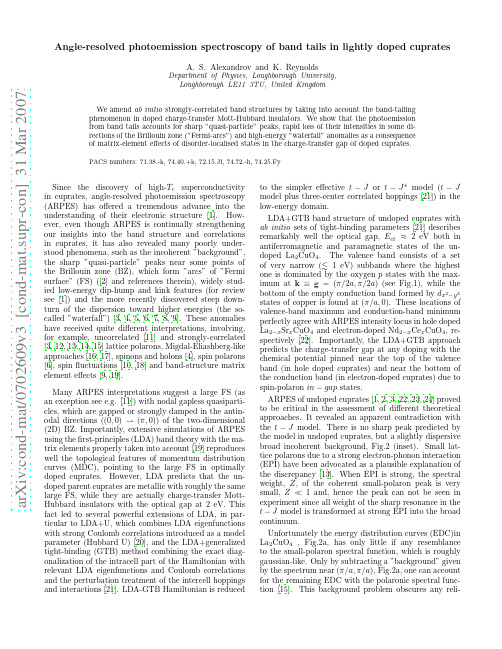
a r X i v :c o n d -m a t /0702609v 3 [c o n d -m a t .s u p r -c o n ] 31 M a r 2007Angle-resolved photoemission spectroscopy of band tails in lightly doped cupratesA.S.Alexandrov and K.ReynoldsDepartment of Physics,Loughborough University,Loughborough LE113TU,United KingdomWe amend ab initio strongly-correlated band structures by taking into account the band-tailing phenomenon in doped charge-transfer Mott-Hubbard insulators.We show that the photoemission from band tails accounts for sharp ”quasi-particle”peaks,rapid loss of their intensities in some di-rections of the Brillouin zone (”Fermi-arcs”)and high-energy ”waterfall”anomalies as a consequence of matrix-element effects of disorder-localised states in the charge-transfer gap of doped cuprates.PACS numbers:71.38.-k,74.40.+k,72.15.Jf,74.72.-h,74.25.FySince the discovery of high-T c superconductivity in cuprates,angle-resolved photoemission spectroscopy (ARPES)has offered a tremendous advance into the understanding of their electronic structure [1].How-ever,even though ARPES is continually strengthening our insights into the band structure and correlations in cuprates,it has also revealed many poorly under-stood phenomena,such as the incoherent ”background”,the sharp ”quasi-particle”peaks near some points of the Brillouin zone (BZ),which form ”arcs”of ”Fermi surface”(FS)([2]and references therein),widely stud-ied low-energy dip-hump and kink features (for review see [1])and the more recently discovered steep down-turn of the dispersion toward higher energies (the so-called ”waterfall”)[3,4,5,6,7,8,9].These anomalies have received quite different interpretations,involving,for example,uncorrelated [11]and strongly-correlated [3,12,13,14,15]lattice polarons,Migdal-Eliashberg-like approaches [16,17],spinons and holons [4],spin polarons [6],spin fluctuations [10,18]and band-structure matrix element effects [9,19].Many ARPES interpretations suggest a large FS (as an exception see e.g.[11])with nodal gapless quasiparti-cles,which are gapped or strongly damped in the antin-odal directions ((0,0)→(π,0))of the two-dimensional (2D)BZ.Importantly,extensive simulations of ARPES using the first-principles (LDA)band theory with the ma-trix elements properly taken into account [19]reproduces well the topological features of momentum distribution curves (MDC),pointing to the large FS in optimally doped cuprates.However,LDA predicts that the un-doped parent cuprates are metallic with roughly the same large FS,while they are actually charge-transfer Mott-Hubbard insulators with the optical gap at 2eV.This fact led to several powerful extensions of LDA,in par-ticular to LDA+U,which combines LDA eigenfunctions with strong Coulomb correlations introduced as a model parameter (Hubbard U)[20],and the LDA+generalized tight-binding (GTB)method combining the exact diag-onalization of the intracell part of the Hamiltonian with relevant LDA eigenfunctions and Coulomb correlations and the perturbation treatment of the intercell hoppings and interactions [21].LDA-GTB Hamiltonian is reducedto the simpler effective t −J or t −J ∗model (t −J model plus three-center correlated hoppings [21])in the low-energy domain.LDA+GTB band structure of undoped cuprates with ab initio sets of tight-binding parameters [21]describes remarkably well the optical gap,E ct ≈2eV both in antiferromagnetic and paramagnetic states of the un-doped La 2CuO 4.The valence band consists of a set of very narrow ( 1eV)subbands where the highest one is dominated by the oxygen p states with the max-imum at k ≡g =(π/2a,π/2a )(see Fig.1),while the bottom of the empty conduction band formed by d x 2−y 2states of copper is found at (π/a,0).These locations of valence-band maximum and conduction-band minimum perfectly agree with ARPES intensity locus in hole doped La 2−x Sr x CuO 4and electron-doped Nd 2−x Ce x CuO 4,re-spectively [22].Importantly,the LDA+GTB approach predicts the charge-transfer gap at any doping with the chemical potential pinned near the top of the valence band (in hole doped cuprates)and near the bottom of the conduction band (in electron-doped cuprates)due to spin-polaron in −gap states.ARPES of undoped cuprates [1,2,3,22,23,24]proved to be critical in the assessment of different theoretical approaches.It revealed an apparent contradiction with the t −J model.There is no sharp peak predicted by the model in undoped cuprates,but a slightly dispersive broad incoherent background,Fig.2(inset).Small lat-tice polarons due to a strong electron-phonon interaction (EPI)have been advocated as a plausible explanation of the discrepancy [13].When EPI is strong,the spectral weight,Z ,of the coherent small-polaron peak is very small,Z ≪1and,hence the peak can not be seen in experiment since all weight of the sharp resonance in the t −J model is transformed at strong EPI into the broad continuum.Unfortunately the energy distribution curves (EDC)in La 2CuO 4,Fig.2a,has only little if any resemblance to the small-polaron spectral function,which is roughly gaussian-like.Only by subtracting a ”background”given by the spectrum near (π/a,π/a ),Fig.2a,one can account for the remaining EDC with the polaronic spectral func-tion [15].This background problem obscures any reli-FIG.1:LDA+GTB valence band dispersion[21]amended with band tails(ladder lines)nearΓ,(π/2,π/2)and(π,π) maxima(here k is measured in1/a)able interpretation of the broad ARPES intensities,espe-cially in underdoped cuprates,where the charge-transfer gap at2eV makes inelastic scattering events implausi-ble as an explanation of the background.Sharp peaks at(π/2a,π/2a)near the Fermi level,Fig.2b,in doped cuprates also remains a puzzle.Small heavy polarons cannot screen EPI in lightly doped cuprates.Hence,if Z is small in the parent cuprate,it should also remain small atfinite doping,so that the emergency of the peaks cannot be explained by a substantial increase of Z with doping.Here we show that amending the LDA+GTB band structure of doped cuprates by inevitable impurity band-tails,the ARPES puzzles as mentioned above are ex-plained.Doping of cuprates inserts a large number of impuri-ties into the parent lattice.Each impurity ion locally introduces a distinct level,E i,in the charge-transfer gap.The fact that the impurities are randomly dis-tributed in space causes the density of states(DOS)to tail,like in heavily doped semiconductors[25].When there are many impurities within the rangeξi of a lo-calised wave functionψi(r),the random potential pro-duces low-energy states near maxima of the valence band at hole doping,Fig.1,or near minima of the conduction band at electron doping.As a result,ARPES intensity, I(k,E)=I b(k,E)+I im(k,E)comprises the band-tail intensity,I im(k,E),due to localised states within the charge-transfer gap,and the valence band contribution, I b(k,E),of itinerant Bloch-like states.According to LDA band structures[19]the itinerant states are anisotropic-3D(specifically in La2CuO4)dispersing with c-axis k z over a few hundred meV.We suggest that this dispersion shapes the background making it so different from the incoherent background caused by EPI and/or spinfluc-tuations since k z is not conserved in ARPES experiments. On the other hand the incoherent background can be well described by a simple polaronic Gaussian in presumably more anisotropic insulating Ca2CuO2Cl2[24].Here we focus on the band-tailing contribution de-scribed by the Fermi-Dirac golden rule asI im(k,E)=2πe2vm3/2(E+∆)5/2k x a /π=k y a/π=0.560.530.500.470.44FIG.2:Band-tail EDC,Eq.(4),(solid lines)with pseudogap ∆=300meV and band-tail width γ=300meV compared with relative EDC (symbols)near (π/2a,π/2a ).Relative in-tensities are obtained by subtracting ARPES intensities of the parent compound,La 2Cu04(a),shifted by δµ,from EDC ofslightly doped La 1.97Sr 0.03CuO 4(b)as measured by Yoshida et al.[2].Both intensities have been normalised by their values at E =−800meV and the chemical potential shift between two samples has been taken as δµ=70meV.We notice that due to a very sharp dependence on q of the matrix element in Eq.(2)any uncertainty of k z does not smear out the strong dependence of I im (k ,E )on the in-plane momentum component,k .Averaging over k z simply replaces M (k −g ,E )in Eq.(3)by ˜M(k −g ,E )≈32c [E +∆+(k −g )2/m ]7/2ρim (E +∆),(4)where c is the c-axis lattice constant.Also M and ˜M can be very large for shallow impurity states,M,˜M≫1/x .Hence even the strong polaronic reduction of their weight,Z ≪1,does not make band-tails invisible in ARPES at finite doping,in contrast to a complete re-duction of the coherent band peak.Since the chemical potential shifts towards the band edge with doping,∆in Eqs.(3,4)becomes smaller.Hence,the band-tail peak,I im (k ,E ),which is propor-tional to x ,not only increases but also becomes sharper with doping as observed [2].To provide more insight into the shape and momentum dependence of experimental EDC we approximate the band-tail DOS by the simple form,ρim (E )=[n/Γ(p/n +1/n )](E/γ)p exp(−E n /γn ),where Γ(x )is the gamma-function.Exponents n,p de-pend on the dimensionality and the correlation length of the disorder potential:n =2both in 2D and 3D,p =2in 2D and p =7/2in 3D for the long range random poten-tial correlations.In the short-range Gaussian-white-noiseB i n d i n g E n e r g y m e Vk x = k y (p/a)FIG.3:Waterfall effect in the band-tail ARPES intensity (white colour corresponds to the highest intensity).FIG.4:Real space Fourier transform (lower panel)of the square root of ARPES intensities (arb.units)at the Fermi level in Ca 2−x Na x CuO 2Cl 2(upper panel,measured by Shen et al.[23]for x =0.12)reveals the real-space size (in units of a )of localised in-gap states.limit one obtains n =1,1/2in 2D and 3D,respectively,and p =3/2in both dimensions [27].We can separate im-purity and band contributions by subtracting normalised ARPES intensity of the parent cuprate from the intensity of the doped one.Then,the band-tail ARPES,Eq.(4),fits well with the experimental relative intensities at all momenta around g with m =m e ,n =2,and p =7/2,Fig.2.It describes the substantial loss of intensity with changing the momentum by only a few percent relative to g ,as well as the shape of the relative EDC.We argue that band-tailing can also contribute to the waterfall effect.There are impurity tails near local max-ima of the LDA+GTB valence band atΓpoint(0,0) and at g1=(π/a,π/a),as shown in Fig.1.Different from in-gap impurity states at g=(π/2a,π/2a)these localised states are hybridised with the valence band states of the same energy(shown by stars in Fig.1). However,the hybridisation could be insignificant,if the corresponding matrix elements of the random potential are small due to a large momentum separation between those states of the order ofπ/2a.Hence,the impurity peaks reappear and disperse towards(0,0)and g1at high binding energies,as observed in a number of doped cuprates[4,5,6,7,8,9].We illustrate the waterfall in Fig.3by adding all three tail contributions,I im(k,E)∝n(E)[˜M(k ,E+E2)+˜M(k −g,E)+˜M(k −g1,E+E2)] where E2is roughly the valence band-width(we chose E2=500meV).We notice that the Fermi-Dirac distribu-tion,n(E),is replaced by its convolution with the Gaus-sian energy resolution function,n(E)→[1−erf(E/δ)]/2 in plotting Figs.2,3since the energy resolutionδ=20 meV is much larger than T≈2meV.Also the photoe-mission intensity comprises both band-tail and valence band contributions,so that the resulting dispersion could be different from the anomalous band-tail dispersion of relative intensities,Fig.2.Our theory proposes that the ARPES intensity near (π/2a,π/2a)is proportional to the square of the Fourier component,f i(q),of the impurity wave-function enve-lope,Eq.(2).Therefore,we canfind the real-space im-age of the function,F i(r),by taking the Fourier trans-form of the square root of the experimental intensi-ties,Fig.4(upper panel).Here we show the intensities near the Fermi level measured in Ca2−x Na x Cu O2Cl2 [23],which are very similar,if not identical to those in La2−x Sr x CuO4(compare Fig.1[23]and Fig.2in[2]).The real-space image(lower panel,Fig.4)reveals some band-mass anisotropy and the size of the localised state of about20lattice constants justifies the”envelope”ap-proximation[26]used for the impurity wavefunction.In summary,we have proposed an explanation for sharp”quasi-particle”peaks,”Fermi-arcs”,and the high-energy waterfall in cuprates as a consequence of matrix-element effects of disorder-localised band-tails in the charge-transfer gap of doped Mott-Hubbard insulators. Importantly if holes are bound into bipolarons,the chem-ical potential remains within the single-particle band-tail at the bipolaron mobility edge even up to optimum dop-ing,in agreement with S−N−S tunnelling experiments [28]and insulating-like low-temperature resistivity of un-derdoped cuprates.In this case∆in Fig.1is half of the bipolaron binding energy[11],which is also the normal state pseudogap[29].Recent scanning tunnelling mi-croscopy at the atomic scale found intense nanoscale dis-order in high-Tc superconductor Bi2Sr2CaCu2O8+δ[30] telling us that band-tailing indeed plays the important role in shaping single-particle spectral functions of doped Mott insulators.We are grateful to ZX Shen and Teppei Yoshida for providing us with their raw ARPES data[2]and enlight-ening comments.We greatly appreciate valuable discus-sions with Arun Bansil,Sergey Borisenko,Ivan Bozovic, Jim Hague,Jan Jung,Alexander Kordyuk,Maxim Kor-shunov,Kyle Shen,and Jan Zaanen.This work was sup-ported by EPSRC(UK)(grant number EP/C518365/1).[1]A.Damascelli,Z.Hussain and Zhi-Xun Shen,Rev.Mod.Phys.75473(2003);X.J.Zhou et al., cond-mat/0604284.[2]T.Yoshida et al.,Phys.Rev.Lett.91,027001(2003).[3]F.Ronning et al.,Phys.Rev.B71,094518(2005).[4]J.Graf et al.,Phys.Rev.Lett.98,067004(2007).[5]W.Meevasana et al.,cond-mat/0612541.[6]B.P.Xie et al.,cond-mat/0607450[7]Z.-H.Pan et al.,cond-mat/0610442.[8]J.Chang et al.,cond-mat/0610880.[9]A.A.Kordyuk et al.,cond-mat/0702374.[10]A.Macridin et al.,cond-mat/0701429.[11]A.S.Alexandrov and C.J.Dent,Phys.Rev.B60,15414(1999);A.S.Alexandrov and C.Sricheewin,Europhys.Lett.58,576(2002).[12]G.Wellein,H.Roder,and H.Fehske,Phys.Rev.B53,9666(1996)[13]A.S.Mishchenko and N.Nagaosa,Phys.Rev.Lett.93,036402(2004).[14]M.Hohenadler et al.,Phys.Rev.B71,245111(2005).[15]O.Rosch et al.,Phys.Rev.Lett.95,227002(2005).[16]J.P.Hague,J.Phys.:Condense Matter15,2535(2003).[17]E.G.Maksimov,O.V.Dolgov,and M.L.Kulic,Phys.Rev.B72,212505(2005).[18]S.V.Borisenko et al.,Phys.Rev.Lett.96,117004(2006).[19]M.Lindroos,S.Sahrakorpi,and A.Bansil,Phys.Rev.B65,054514(2002).[20]V.I.Anisimov,J.Zaanen,and O.K.Andersen,Phys.Rev.B44,943(1991).[21]S.G.Ovchinnikov et al.,J.Phys.:Condens.Matter16,L93(2004);M.M.Korshunov et al.,Phys.Rev.B72, 165104(2005).[22]N.P.Armitage et al.,Phys.Rev.Lett.88,257001(2002);K.M.Shen et al.,Phys.Rev.B69,054503(2004).[23]K.M.Shen et al.,Science307,901(2005).[24]K.M.Shen et al.,Phys.Rev.B75,054503(2007).[25]P.V.Mieghem,Rev.Mod.Phys.64,755(1992).[26]W.Kohn and J.M.Luttinger,Phys.Rev.97,869-883(1955).[27]B.I.Halperin and x,Phys.Rev.148,722(1966);R.Eymard and G.Duraffourg,J.Phys.D:Appl.Phys.6,66(1973);D.N.Quang and N.H.Tung,Phys.Stat.Sol.B209,375(1998).[28]I.Bozovic et al.,Nature(London)422,873(2003).[29]A.S.Alexandrov,in Studies in High Temperature Super-conductors,ed.A.V.Narlikar(Nova Science Pub.,NY2006),50,pp.1-69.[30]J.Lee et al.,Nature(London),442546(2006).。
applied physics reviews-focused review
APPLIED PHYSICS REVIEWS–FOCUSED REVIEWPlasmonics:Localization and guiding of electromagnetic energy in metal/dielectric structuresStefan A.Maier a ͒and Harry A.AtwaterThomas J.Watson Laboratories of Applied Physics,California Institute of Technology,Pasadena,California 91125͑Received 17September 2004;accepted 23March 2005;published online 11July 2005͒We review the basic physics of surface-plasmon excitations occurring at metal/dielectric interfaces with special emphasis on the possibility of using such excitations for the localization of electromagnetic energy in one,two,and three dimensions,in a context of applications in sensing and waveguiding for functional photonic devices.Localized plasmon resonances occurring in metallic nanoparticles are discussed both for single particles and particle ensembles,focusing on the generation of confined light fields enabling enhancement of Raman-scattering and nonlinear processes.We then survey the basic properties of interface plasmons propagating along flat boundaries of thin metallic films,with applications for waveguiding along patterned films,stripes,and nanowires.Interactions between plasmonic structures and optically active media are also discussed.©2005American Institute of Physics .͓DOI:10.1063/1.1951057͔TABLE OF CONTENTSI.INTRODUCTION............................1II.LOCALIZED PLASMON RESONANCES IN METAL NANOPARTICLES...................2A.Optical properties of single metalnanoparticles (2)B.Interacting particle ensembles as a basis for applications of metal nanoparticles inoptical devices (4)C.Local field enhancement around metal nanoparticle structures for sensing andnonlinear applications ....................5III.INTERFACE PLASMON POLARITONS ATMETAL/DIELECTRIC BOUNDARIES.........6A.Surface-plasmon polaritons at metalinterfaces ..............................6B.Metal stripes and nanowires:Two-dimensional confinement .............8C.Apertures in a metallic screen .............8D.Interactions with optically active media .....9IV .OUTLOOK.. (9)I.INTRODUCTIONThe electromagnetic properties of metal/dielectric inter-faces have attracted a vast amount of research effort ever since the work of Mie 1and Ritchie 2for small particles and flat interfaces,respectively.The ability of such structures tosustain coherent electron oscillations known as surface-plasmon polaritons ͑SPPs ͒leading to electromagnetic fields confined to the metallic surface has been intensively investigated 3,4both in light of the fundamental physics in-volved and for applications such as surface-enhanced spec-troscopy and enhancement of nonlinear light generation.Af-ter initial studies of the physics of these excitations,in the 1980s SPPs started to attract the attention of chemists,as the electric-field enhancement around metal nanostructures was found to be crucial for surface-enhanced Raman spectros-copy.More recently,the development of nanofabrication tech-niques such as electron-beam lithography,ion-beam milling,and self-assembly,together with modern nanocharacteriza-tion techniques such as dark-field and near-field optical mi-croscopies and the emergence of quantitative electromag-netic simulation tools,has lead to a resurgence of interest in this field,5partly due to potential applications for creating subwavelength optical devices enabling the miniaturization of optical components to size dimensions of their electronic counterparts,i.e,to the sub-100-nm-size regime.The unify-ing physical processes enabling light localization and guid-ing in such structures are the above-mentioned SPP excita-tions,and the name “plasmonics”for the subfield of modern optics studying such processes has been proposed.6Due to the vast amount of research in this exploding field,5we naturally had to select a rather small amount of topics for this review,leading to the omission of important applications of SPPs,for example,their use in integrated biological sensors based on multilayer structures,7investiga-tions from a more chemical viewpoint,8as well as an in-depth treatment of fabrication techniques.9Here,we limit ourselves to a discussion of the fundamental physics ofa ͒Present address:Department of Physics,University of Bath,Bath BA27AY ,U.K.;electronic mail:s.maier@JOURNAL OF APPLIED PHYSICS 98,011101͑2005͒0021-8979/2005/98͑1͒/011101/10/$22.50©2005American Institute of Physics98,011101-1surface-plasmon excitations both for localized plasmons in metallic nanoparticles and for interface plasmons at metall-odielectric film boundaries.A special focus has been put on the localization and guiding properties for electromagnetic radiation in light of applications of plasmon excitations for surface-enhanced spectroscopy such as sensing and higher harmonic generation and for the creation of a planar wave-guide technology that can beat the diffraction limit.II.LOCALIZED PLASMON RESONANCES IN METAL NANOPARTICLESA.Optical properties of single metal nanoparticlesThe strong interaction of microscopic metal particles of dimensions below 1m with visible light has been em-ployed for beautiful applications long before Gustav Mie’s seminal 1908paper Beiträge zur Optik trüber Medien,spez-iell kolloidaler Metallösungen ͑contributions to the optics of turbid media,particularly solution of colloidal metals ͒.1His-torically,one prominent use of metal nanoparticles has been the staining of glass windows and ceramic pottery as seen in Fig.1͑a ͒by example of the Lycurgus cup ͑Byzantine empire,4th century A.D.͒.The glass cup,on display in the British Museum,shows a striking red color when viewed in trans-mitted light,while appearing green in reflection.This pecu-liar behavior is due to small Au nanoparticles embedded in the glass ͓Fig.1͑b ͔͒,which show a strong optical absorption of light in the green part of the visible spectrum ͓Fig.1͑c ͔͒.Indeed,the optical properties of metal nanoparticles,es-pecially those of the noble metals Au,Ag,and Cu,show striking differences relative to their bulk or thin-film optical responses.As an example,Fig.1͑c ͒shows the calculated absorption of a thin Au film ͑blue dots ͒,as well as that of 30-nm Au spheres immersed in water ͑red dots ͒,where the dispersion properties of Au have been modeled using mea-sured dielectric data for bulk Au.10For the nanoparticles,the optical-absorption spectrum has been obtained by directlysolving Maxwell’s equations for the scattering of electro-magnetic waves by spherical objects as carried out by Mie,1and retaining only the dipolar term,which is suitable for nanoparticles with a diameter d Ӷ,where is the wave-length of light in the surrounding medium.As shown,this quasistatic approximation is in good agreement with mea-surements ͑black dots ͒,which has been confirmed via a plethora of studies of the optical response of metallic nano-particles with a diameter well below in solid,liquid,and gaseous environments.4Figure 1͑c ͒further demonstrates a striking difference between the optical response of the thin film and the nanoparticles.Whereas the film absorbs light throughout the near-infrared and visible regions due to free-electron absorption,for the nanoparticles this process is strongly quenched for energies lower than 2eV ͑correspond-ing to wavelengths larger than 620nm ͒.Indeed,all the free-electron oscillator strength for absorption is pulled into a dipolar absorption peak around 2.25eV,the dipolar surface-plasmon particle resonance.This modified optical response leads to the bright colors of noble-metal nanoparticles,a nice discussion of which can be found in Ref.11.For higher energies above the dipole resonance,the optical absorption of particles and films is similar,due to the dominance of d –sp electronic interband transitions,which are prominent for Au and Cu in the vicinity of the dipole plasmon reso-nance,but less so for Ag.The resonant electromagnetic behavior of noble-metal nanoparticles is due to the confinement of the conduction electrons to the small particle volume.For particles with a diameter d Ӷ,the conduction electrons inside the particle move all in phase upon plane-wave excitation with radiation of wavelength ,leading to the buildup of polarization charges on the particle surface.These charges act as an ef-fective restoring force,allowing for a resonance to occur at a specific frequency—the particle dipole plasmon frequency-,where the response of the electrons shows a /2phase lag with respect to the driving field.Thus,a resonantly enhanced field builds up inside the particle,which in the small particle limit is homogeneous throughout its volume,producing a dipolar field outside the particle.This leads to enhanced ab-sorption and scattering cross sections for electromagnetic waves,as well as to a strongly enhanced near field in the immediate vicinity of the particle surface.It is this reso-nantly enhanced near field from which most of the promising applications of metal nanoparticles stem.For larger particles,the spectral response is modified due to retardation effects and the excitation of higher-order ͑quadrupole and higher ͒modes,the spectral signature of which can be calculated by retaining higher orders of the Mie theory scattering coefficients.1In general,the spectral position,damping,and strength of the dipole as well as of the higher-order plasmon reso-nances of single metal nanoparticles depend on the particle material,size,geometry,and the dielectric function of the surrounding host.4For theoretical considerations,the large variety of naturally occurring or synthesized shapes of nano-particles is often approximated via spheres or spheroids,for which analytically exact solvable solutions exist to all orders.1,4,12,13The analysis is further facilitated forparticlesFIG.1.͑Color online ͒͑a ͒The Lycurgus glass cup,demonstrating the bright red color of gold nanocrystals in transmitted light.͑b ͒scanning electron microscopy ͑SEM ͒image of a typical nanocrystal embedded in the glass ͑courtesy of the British museum ͒.͑c ͒Calculated absorption spectrum of a thin gold film ͑blue dots ͒and of 30-nm Au nanoparticles in water ͑red dots ͒using classical electromagnetic theory.A measured absorption spectrum of an aqueous solution of 30-nm Au colloids ͑black dots ͒shows good agree-ment with the theory.much smaller than the wavelength of light,where only the lowest ͑dipolar ͒order of the modal expansion of the scat-tered fields has to be retained.In this case,a quasistatic ap-proach serves well to describe the spectral position,width,and strength of the dipolar plasmon resonance,as pointed out in the discussion of Fig.1.For a spherical metal nanoparticle of radius a Ӷembedded in a nonabsorbing surrounding me-dium of dielectric constant m ,the quasistatic analysis gives the following expression for the particle polarizability ␣:␣=4a 3−m+2m,͑1͒with the complex =͑͒describing the dispersive dielectric response of the metal.The polarizability and thus the in-duced homogeneous polarization inside the particle are reso-nantly enhanced at the Fröhlich frequency where the de-nominator shows a minimum,limited by the imaginary part of describing Ohmic heating losses within the particle.These losses are due to the creation of electron-hole pairs,the energy of which is subsequently coupled to the phonon bath.14The spectral position of this resonance is seen to red-shift with increasing dielectric constant of the surrounding host due to the buildup of polarization charges on the dielec-tric side of the interface,thus weakening the total restoring force.For ellipsoidal particles with principal axes a ,b ,and c ,an analogous expression can be found in the quasistatic ap-proximation via introducing geometrical depolarization fac-tors L i along these axes,4,12leading to␣=43abc−m m +L i ͑−m ͒,͚L i =1.͑2͒For spherical particles,L 1=L 2=L 3=1/3.For spheroidal par-ticles ͑L 1=L 2͒,the plasmon resonance thus splits into astrongly redshifted long-axis mode ͑polarization parallel to the long axis ͒and a slightly blueshifted short axis mode ͑polarization perpendicular to the long axis ͒.12For larger particles beyond the Rayleigh approximation,the dipolar resonance redshifts while at the same time suffer-ing substantial broadening.The redshift is due to a reduction of the depolarization field due to retardation effects 15—the conduction electrons do not all move in phase anymore,leading to a reduced depolarization field at the particle centergenerated by the surrounding polarized matter.Additionally,radiative losses 16begin to significantly contribute to the plas-mon damping,dominating the total damping of Au and Ag nanoparticles for particle sizes in excess of 100nm.The de-polarization field and radiation damping effect can be seen as lowest-order corrections to the quasistatic theory,leading to additional real and imaginary parts of the denominator of the polarizability.A generalization of the quasistatic approach to particles of arbitrary shape has been suggested,with surpris-ingly good results 17͓see Fig.2͑a ͔͒.For particles with a di-ameter smaller than the free-electron scattering length,scat-tering processes at the particle surface are thought to begin to contribute to the total damping.4These additional damping mechanisms for large and small particles lead to respective decreases in the total enhancement of the exciting field via a decrease of the plasmon dephasing time T 2.4Generally,numerical methods such as the T -matrix method,18the discrete dipole approximation 19͓Fig.2͑b ͔͒,or finite-difference time-domain simulations 20have to be used to calculate the resonance frequencies and mode profiles of more complex shapes.Such simulations have especially been employed to determine the local-field enhancement at the particle surface,in conjunction with discussions of enhance-ments of nonlinear processes and surface-enhanced Raman scattering ͑SERS ͒as discussed below.Experimentally,sophisticated modern fabrication meth-ods allow for the fabrication of metal nanoparticles and other nanostructures of a variety of shapes using both colloidal synthesis methods 21and top-down nanofabrication tech-niques such as electron-beam lithography,22and a wide vari-ety of methods for the fabrication of metallic nanoparticles and ensembles thereof have recently been described in a dif-ferent review article.9The good control over the size and shape of the particles provided by these methods method allows one generally to observe homogeneously broadened line shapes of dipolar 23and multipolar 24plasmon modes in particle ensembles using conventional far-field spectroscopy.The direct examination of single particles has been demon-strated using both dark-field 25and near-field optical microscopies.26The former method allows for a dramatic visualization of the spectral properties of single particles,as can be seen by the example in Fig.2͑a ͒.FIG.2.͑Color online ͒͑a ͒Dark-field microcopy image ͑top ͒and light-scattering spectra ͑bottom ͒of Au nanocrystals of different shapes ͑adapted from Ref.17͒.The measured spectra ͑black curves ͒show good agreement with predictions from a simple analytical extension of quasi-static Mie theory ͑open circles ͒.͑b ͒Electric near-field profile of the lowest-order modes of Ag nanoprisms calculated using the discrete dipole ap-proximation formalism ͑adapted from Ref.54͒.B.Interacting particle ensembles as a basis forapplications of metal nanoparticles in optical devicesAdvances in particle synthesis and fabrication tech-niques ͑for example,Refs.22,27,and 28͒have recently allowed for studies of ordered arrays of noble-metal nano-particles.In such arrays,each nanoparticle with a diameter much smaller than the wavelength of the exciting light acts as an electric dipole.Thus,two types of electromagnetic in-teractions between the particles can be distinguished,de-pending on the spacing d between adjacent nanoparticles.For particle spacings on the order of the exciting wavelength ,far-field dipolar interactions with a d −1dependence domi-nate.Work on regular two-dimensional arrays of Au nano-particles has indeed confirmed the existence of such interac-tions,and quantified their influence on both the spectral position of the collective dipolar extinction peak and the plasmon damping characteristics.29Figures 3͑a ͒and 3͑b ͒show an example of the dependence of both extinction peak and plasmon decay time on the grating constant d for a regu-lar square array of 150-nm-diameter Au nanoparticles.Both the variation of the spectral position and width of the reso-nances can be explained by assuming far-field dipolar interactions—the ensemble acts effectively as a grating,lead-ing to increased radiation damping of the collective reso-nances for grating constants where grating orders change from evanescent to radiative in character.29Applications of such ordered arrays lie,for example,in the possibility of maximizing surface-enhanced Raman scattering of adsorbed molecules by careful spectral tuning of the plasmon resonance.30For particle spacings much smaller than the wavelength of light,near-field dipolar interactions between adjacent par-ticles with a distance dependence of d −3dominate.23,31These strongly distance-dependent interactions lead to a splitting of the plasmon dipolar peak for regular one-dimensional arrays of metal nanoparticles as seen in Fig.3͑c ͒for ordered arrays of 50-nm Au particles.The spectral position of the extinction peak for far-field excitation shows a blueshift for polarization perpendicular to the chain axis ͑T ͒,and a redshift for longi-tudinal polarization ͑L ͒,which can easily be understood by analyzing Coulombic force interactions between the elec-trons in neighboring particles.The near-field interactions be-tween such particles have been directly visualized using near-field optical microscopy,32confirming a strongly en-hanced field between the particles ͓Fig.3͑d ͔͒,indicative of near-field coupling.One application of near-field coupling between particles in ordered arrays is the use of such structures as waveguides for electromagnetic energies at optical frequencies with a lateral mode profile below the diffraction limit of light.6,33Indeed,it has been shown both theoretically 34and experimentally 35that such arrays can guide electromagnetic energy over distances of several hundred nanometers via near-field particle interactions.Such structures could poten-tially be used in nanoscale all-optical networks,contributing to a class of functional optical devices below the diffraction limit of light.5,6,36Localized plasmon excitations mediated by particle in-teractions also occur in randomly nanostructured metallic surfaces.37In this case,multiple-scattering processes can lead to “hot spots”of extremely large field enhancement ͑on the order of 1000͒,which has enabled the use of such struc-tures for single-molecule spectroscopy.38FIG.3.͑Color online ͒͑a,b ͒Measured extinction spectrum ͑a ͒and plasmon decay time ͑b ͒for regular two-dimensional ͑2D ͒square arrays of Au nanoparticles ͑adapted from Ref.29,copyright by the American Physical Society ͒.Both the spectral position and the decay time of the collective dipolar plasmon mode show a marked variation with grating constant due to far-field dipolar interactions.͑c ͒Mea-sured spectral position of the collec-tive plasmon resonances of one-dimensional arrays of closely spaced Au nanoparticles for longitudinal ͑L ͒and transverse polarizations ͑T ͒.Also shown are results of a simple near-field point-dipolar coupling model ͑solid lines ͒and finite-difference time-domain simulations ͑stars ͒.͑d ͒Optical near-field around such a chain ob-tained using collection mode near-field optical microscopy ͑left ͒and numeri-cal simulations ͑right ͒,adapted from Ref.32.C.Localfield enhancement around metal nanoparticle structures for sensing and nonlinear applications The enhanced nearfields around metallic nanostructures induced by illumination at visible and near-infrared frequen-cies allow for a variety of intriguing applications apart from energy guiding in ordered particle arrays discussed above. Since the enhancedfields are localized to the surface of the nanostructures,they serve as a local probe of the dielectric environment within a few nanometers of the particle surface. This fact has,for example,been employed in studying varia-tions of the local refractive index in light of biological ͑mass͒sensing applications.39–41Also,the local response of metallic nanostructures can serve so as to enhance the in-coming and generatedfields for nonlinear processes and de-cay rate enhancements of emissive species.For nonlinear applications and surface-enhanced Raman sensing,the local-field E Local close to the metal surface should be maximized so as to maximize the respective higher-order processes,neglecting the possibility of absorption-induced damage of the optically active medium. The local-field enhancement factor L=E Local/E0,with E0be-ing the amplitude of the incomingfield,can for a single nanoparticle be written as the product of two factors L =L SP͑͒L LR,highlighting two possible enhancement processes—the surface-plasmon resonance of the whole par-ticle͑L SP͒and the lightning rod effect͑L LR͒.For larger par-ticles,surface roughness and crevices can lead to additional localized resonances forming hot spots on the particle sur-face.For a perfectly spherical particle in the Rayleigh limit, only the dipole surface-plasmon resonance contributes to the enhancement process,with L SPϰQϰT2in the absorption-dominated regime,where T2and Q are the dephasing time, limited by the decay of the particle plasmon into electron-hole pairs and photons and by phase-destroying elastic scat-tering processes,and the quality factor of the resonance,re-spectively.The origins of plasmon decay and dephasing have been extensively discussed in the literature,14,42and T2has been determined both using time-resolved pump-probe measurements43–46and higher harmonic generation.47For small Au nanospheres in air and low-index matrixes,plas-mon excitation competes with interband transitions,leading to low Q factorsϳ10,while radiation damping dominates for larger spheres with diameters of about100nm.16Higher Q factorsϳ20have been reported for spheroidal Au par-ticles,due to a redshift of the long-axis dipolar resonance away from the interband transition edge.42For Ag nanopar-ticles,the respectivefield enhancements at visible frequen-cies are higher,partly due to a larger spectral separation of the plasmon resonance from the interband transition edge. Another promising route to larger quality factors are metallic nanoshells,where Q factors up to150have been estimated for Ag.48For nonspherical shapes,the geometric and only weakly frequency-dependent lightning rod effect L LR of the electric field at sharp surface protrusions,leading to an increased surface charge and thus a crowding of the electric-field lines, serves as an additional enhancement process.49–51This way,highly localizedfields can be generated at the tips of elon-gated spheroids or rough surfaces.For very rough or veryhigh-aspect ratio particles,additionally local-plasmon reso-nances at specific parts on the particle surface can be excited,leading to an additional enhancement.For the case of sphe-roids with aspect ratiosϾ10:1,the overall particle resonancecan be interpreted as an antenna effect,where thefield isfurther enhanced at the tip due to lightning rod and localplasmon resonances.13,52Fully analytical53and a variety ofnumerical models54have been used to quantify thefield en-hancement at sharp points on a variety of single-metal par-ticles,predicting highest-field enhancement factors of about100for Ag particles.The heightened opticalfields near metal nanostructuresmanifest themselves in the enhancement of higher harmonicgeneration and local spectroscopy.For example,the total en-hancement of second-harmonic generation on a rough silversurface is expected to scale as L͑͒4L͑2͒2upon resonance, whereas for Raman spectroscopy the enhancement scales asL͑exc͒2L͑RS͒2.Note that due to the small Stokes shift in Raman scattering,usually thefields at both the excitationfrequency and the Stokes frequency are enhanced.Forsecond-harmonic generation on the other hand,usually onlyone of the two processes shows enhancement due to the largespectral separation between the two lines.Also,due to thesignificant absolute value of͉͉͑͒at visible frequencies,the field inside the particle͑where second harmonic generation from the particle itself occurs͒is smaller than thefield out-side͑where SERS occurs͒.Thus,the observed SERS en-hancements are usually significantly larger than those of second-and higher harmonic processes.Note that for calcu-lations offield enhancement with metallic nanoparticles,the enhancement is usually evaluated for the peak power at a specific Stokes or higher harmonic output frequency,i.e.,not integrated over the total resonance line shape.Experimentally,the enhancement of second-harmonicgeneration at rough metal surfaces has been observed usingboth far-field55–58and near-field59,60spectroscopic tech-niques,with measured enhancements of second-harmonicgeneration on Au and Ag islandfilms up to1000.58While themagnitude of the reported enhancement varies considerably,recently direct observations of localized second-harmonicenhancements of order1000have been reported on Au sur-faces coated with random scatterers using laser scanningmicroscopy.61,62The highest enhancement of an optical process on arough metal surface so far reported is that of Raman Stokesscattering͑surface-enhanced Raman scattering͒,where emis-sion from single molecules63,64with an enhancement factorof the Raman cross section up to1014has been observed,although the interpretation of these experiments is somewhatcontroversial.At this point,it is believed that this huge in-crease in the cross section is due to both local-field enhance-ments up to a factor of1000on roughened Ag surfaces,leading to a Raman enhancement of1012,and to chemicaleffects due to adsorbate binding at the metal surface,65mak-ing up for the additional factor of100in the total enhance-ment.Sincefield enhancements of a factor of1000canhardly be achieved for single particles,with the possible ex-ception of gap modes in surface crevices,it is believed that field localization in small gaps between metal particles due to geometric effects and multiple photon scattering on rough surfaces contributes to this high-field enhancement in nanometer-sized volumes,so-called hot spots,53,54,62and re-cently a detailed analytical description of the enhancement using a simple resonator model has been given.66These lo-calized resonances tend to show very different strengths,po-larization,and localization characteristics.The importance of multiple scattering for the creation of hot spots for field en-hancement has been highlighted via many studies showing the significance of fractal-like character of the silver surface.37,67III.INTERFACE PLASMON POLARITONS AT METAL/DIELECTRIC BOUNDARIESA.Surface-plasmon polaritons at metal interfacesCoherent electron oscillations leading to enhanced local fields at the surface of metallic structures cannot only be excited in metallic nanoparticles,but also at flat interfaces such as metallic films.As is well known,the interface be-tween a metallic film and a dielectric can sustain SPPs in the form of coherent longitudinal charge oscillations of the con-duction electrons,thus leading to a surface wave confined within one dimension perpendicular to the surface.3At flat interfaces,these charge oscillations were observed in energy loss spectra obtained via bombardment of the film with fast electrons,revealing “low-lying plasma losses”at energies lower than the characteristic bulk-plasmon energy p of the respective metal.2,68At a metal/air boundary,these low-lying plasma losses for electrons occur at a frequency p /ͱ2.This lowering of the plasmon resonance is due to the depolarizing effect of the flat surface,analogous to the case of localizedplasmons in metallic nanoparticles.However,while for exci-tation with fast electrons plasma waves at flat interfaces do not propagate ͑group-velocity g =0͒,SPPs at lower energies exhibit a significant dispersion with wave vector k due to retardation effects.Figure 4͑a ͒shows the dispersion relation for surface-plasmon polaritons propagating at a flat interface between Ag and air,glass,and silicon,respectively,calcu-lated using a simple boundary condition analysis for electro-magnetic surface waves,3yieldingk x =c ͫ͑͒2͑͒+2ͪ,͑3͒where ͑͒are the ͑complex ͒dielectric function of the metal and 2the dielectric constant of the adjacent dielectric half-space.As can be seen,the dispersion relations of the SPPs al-ways lie to the right of the respective light line,approaching sp =p /ͱ1+2for large wave vectors,the magnitude of the wave vector at sp being limited by dissipation.While ex-periments with fast electrons mainly probe this high wave-vector regime where dispersion is absent,3for lower wave vectors surface-plasmon polaritons can be excited by TM-polarized light,providing that the retardation-induced mo-mentum mismatch is compensated.The main techniques for achieving this momentum matching are prism coupling,cou-pling via surface grating or roughness ͑defects ͒,and using highly focused optical excitation.3Recently,excitation of surface plasmons using regular hole arrays created via shad-owed metal evaporation has been achieved.69This work has provided a beautiful demonstration of the transition between localized surface plasmons of nontouching particles to dis-persive surface-plasmon polaritons propagating along the hole film ͓Figs.4͑b ͒–4͑d ͔͒.FIG.4.͑a ͒Calculated dispersion of surface plasmon-polaritons propagating at a Ag/air,Ag/glass,and Ag/Si interface,respectively.͑b ͒–͑d ͒Measured transmittance as a function of in-plane wave vector and frequency for p -polarized light incident upon an array of nontouching nanoparticles ͑b ͒,an intermediate array of bigger particles with some coalescence ͑c ͒,and a periodic array of holes formed by touching nanoparticles ͑d ͒,showing the transition from localized to dispersive behavior ͑adapted from Ref.69͒.。
On the Conductivity Mechanism of Nanocrystalli
On the Conductivity Mechanism of Nanocrystalline CeriaSangtae Kim*,z and Joachim Maier**Max-Planck-Institut fu¨r Festko¨rperforschung,70569Stuttgart,GermanyElectrical conductivities of Gd-doped͑0.15mol%͒and nominally pure nanocrystalline CeO2Ϫx ceramics͑ϳ30nm grain size͒were measured by impedance spectroscopy in the temperature range of673-773K under various oxygen partial pressures͑1-105Pa͒.The ionic and electronic contributions were separated using electrochemical polarization with an electronicallyblocking electrode,yttria-stabilized zirconia.The results allow for a clear distinction between potential explanations.It is shownthat the space charge model͑space charge zones with potential ofϳ0.3V resulting in depletion of oxygen vacancies andaccumulation of conduction electrons͒explains all the experimental features.©2002The Electrochemical Society.͓DOI:10.1149/1.1507597͔All rights reserved.Manuscript submitted December20,2001;revised manuscript received April22,2002.Available electronically September12,2002.In recent years a growing interest in the properties of nanostruc-tured ion conductors has been observed.1-3Nanocrystallinity intro-duces such a high density of the interfaces that the conduction prop-erties may become interfacially controlled.At tiny grain sizes,thedistance of interfaces is expected to become a further control param-eter determining the occurrence of size effects.In view of the paramount importance of CeO2Ϫx as a solid elec-trolyte͑if appropriately doped͒and catalyst material,it is not sur-prising that CeO2Ϫx is one of the most intensively studied oxidematerial in nanocrystalline state.4-7According to the literature theintroduction of nanocrystallinity into CeO2Ϫx is able to change mag-nitude and type of conduction.Thus,nominally pure but usuallyslightly acceptor doped CeO2Ϫx,which conducts predominantlyO2Ϫions͑via oxygen vacancies,V O••),is increased in its conductiv-ity by several orders of magnitude.The resulting negative oxygenpartial pressure,P O2,dependence has been explained by n-type con-ductivity.Although attributing such a negative P O2dependence toconduction electrons,eЈ,is not compulsory͑the usual P O2depen-dencies are derived from electroneutrality͒the literature agrees in this conclusion.A deep discrepancy,however,is met as far as the mechanism is concerned.In what may be called a neutral layer model the interfacial core is held responsible for the enhanced conductivity.Since defect for-mation energies͑for ionic and electronic carriers͒are expected to be diminished͑this is also in accordance with theoretical calculations8͒a high disorder should occur in the interfacial core:Even if the bulkmay be slightly acceptor(AЈ)doped and hence may even be ioni-cally conducting(c AϷ2c vӷc n where c is the concentration and subscripts A,v and n denote AЈ,V O••and eЈ,respectively͒,the neutral layer may still be heavily oxygen deficient͑limit2c v ϭc n),leading to an increased n-type conductivity with a negativeP O2dependence͑electronic conductivityϰP O2Ϫn,nϭ1/6or higherif one allows for acceptor ions in the interfacial core͒.On the other hand,for thermodynamic reasons,the contact of two structurally defined regions͑here interfacial core and bulk͒nec-essarily leads to a redistribution of ionic and electronic carriers. While in the above model the charging of the interfacial core has been neglected,in the second model this charging is held respon-sible for the effect.Conductivity may occur through the core charge with a core mobility but more plausibly through the space charges in the bulk-like boundary structure.Tschoepe7specifically discussed this explanation based on detailed space charge models developed earlier.9,10If the space charge potential is positive͑i.e.,positive core charge͒,positive carriers such as V O••and electron holes,h•,are depleted and negative carriers,e.g.,eЈ,are enhanced,leading to an increased n-type conductivity.If the sample size becomes compa-rable to or smaller than the Debye length,the excess charge com-prises the entire material.The a priori significance of the space-charge concept lies in the fact that indeed positive space charge potentials ofϳ0.3to 0.5V have been obtained not only for polycrystalline Fe-doped SrTiO3,11and Y-doped ZrO2,12but also for CeO2Ϫx.13The magni-tude ofϳ0.3V for CeO2Ϫx is sufficient to cause an n-type conduc-tivity enhancement of the observed order of magnitude as far as the nanocrystalline materials are concerned.It becomes clear that a re-liable answer as to what explanation is correct requires a direct separate determination of ionic and electronic conductivities and a quantitative analysis of the models.While in the neutral layer model also the ion conductivity should,as long as the mobility of the vacancy is not significantly lowered,be enhanced in the interfacial core,severe depletion of V O••͑doubly ionized͒and hence a severe depression of the ionic conductivity should occur in the space charge zones.Note that relative depletion of V O••is equal to the square of the relative enhancement of eЈ.It is shown in the following that the two models lead to quite different predictions as regards impedance response,P O2and tem-perature͑T͒dependencies of partial conductivities and capacitances, which allows for a clear distinction.It is also shown that the results can be consistently explained by the space charge model in all de-tails.TheoryFigure1shows a section of a bricklayer ceramic model exhibit-ing bulk and interfacial core regions of different structures and also space charge zones.As can be seen,the grain boundaries are partly connected in series͑fraction1/3͒and partly connected in parallel ͑fraction2/3͒͑see Ref.9for detail͒.In the neutral layer model,the excess charge in the core is ne-glected and decreased formation energies͑corresponding to weaker bonding͒lead to greater c n s and c vs values than the bulk values͑s denotes the interfacial core͒.Assuming similar mobilities both ionic and electronic transport is expected to be enhanced along the paral-lel interfacial core regions͑a similar mobility as in the bulk should be less of a problem for V O••than for eЈ).In the space-charge model the electronic conduction should be determined by parallel space charge zones͑the mobility of the core charge is neglected͒.Since the space charge zones are strongly de-pleted of V O••,the ionic conduction should almost exclusively pro-ceed along the bulk path.Note,however,that for a long-range con-duction of V O••,extreme boundary resistances have to be overcome ͑see Fig.1b͒.The serial depletion layers may dominate the dc resis-tance or at least show up in the impedance spectrum as a separate low frequency arc.In Ref.9it is shown in detail how the different regions have to be superimposed for the overall dc and ac response.A good approximation is*Electrochemical Society Student Member. **Electrochemical Society Active Member. z E-mail:s.weiglein@fkf.mpg.de 0013-4651/2002/149͑10͒/J73/11/$7.00©The Electrochemical Society,Inc.ˆm ϭˆϱˆgb Ќϩ͑2/3͒gb ˆgb ͉͉ˆgbЌˆgb ϩ͑1/3͒gb ˆϱ͓1͔where ˆis the complex conductivity,is the volume fraction,and subscripts ϱand gb denote bulk and grain boundary,respectively.Superscripts Ќand ͉͉denote series and parallel contributions.The lower index m always refers to the total sample ͑total grain ͒average,whereas otherwise we refer to the specific region ͑ϱor gb ͒͑see also,Appendix for detail ͒.͑Equation 1has been derived for a single-carrier situation and is only partly correct if the transference number of the carrier in bulk and boundary is significantly changed,see below.͒The effective space charge contributions depend on whether we face a Mott-Schottky or a Gouy-Chapman-type situation ͑see below in detail ͒,whether we face accumulation layers,depletion layers,or inversion layers,and whether we consider the transport along or across the space charge zones.The overall values for the respective effective conductivity or resistivity contributions are described in detail in Ref.14.Since we refer to the same electrical potential profiles and the same local conditions,the unknown parameters viz.the boundary values,c n 0or c v0,are ͑in local equilibrium ͒subjected to the follow-ing consistency condition ͑mass action law at x ϭ0where x is the distance from the interface,and x ϭ0refers to the first layer with bulk ͒c n 02c v0ϭc n ϱ2c v ϱϭK ͑T ͒P O 2Ϫ1/2͓2͔where K (T )is the bulk equilibrium constant for the defect forma-tion reactionO O x ↔V O ••ϩ2e Јϩ1/2O 2͓3͔In particular,as far as the P O 2and T dependencies are concerned,itis required that2ץln c n 0ץln P O 2ϩץln c v0ץln P O 2ϭϪ12͓4͔Ϫk B ͫ2ץln c n 0ץ1/T ϩץln c v0ץ1/Tͬϭ⌬H f,v͓5͔where ⌬H f,vis the reduction enthalpy of the Eq.3,and k B is the Boltzmann constant.In the following we briefly discuss different types of the most important issues concerning Gouy-Chapman and Mott-Schottky lay-ers.According to the constancy of the electrochemical potential ͑i.e.,ץ˜j (x )/ץx ϭ0,where ˜j ϭj ϩz j e with and being the chemical and the electrostatic potential,respectively,and e beingelementary charge ͒for any mobile charge carrier j ͑e Јand V O••in CeO 2Ϫx ),the concentration profile follows asc j ͑x ͒c ϱϭexp ͩϪz j ek B T⌬͑x ͓͒ͪ6͔where ⌬(x )is the electrical potential relative to the bulk.As al-ready done in Eq.4and 5,Eq.6assumes ͑this is presupposed throughout the paper ͒that the structural variations up to the bound-ary value ͑x ϭ0͒can be neglected.Making use of the second relation between ⌬(x )and the defect concentrations,viz.Pois-son’s equation together with boundary conditions,the concentration profiles can be derived.As already mentioned above,such concentration profiles in the space charge zones are in general described by Gouy-Chapman and Mott-Schottky profiles.Let us assume that we can concentrate on two majority carriers ͑one of which may be the dopant ͒.If both the two majority carriers can follow the electric field we obtain Gouy-Chapman layers.For large effects they can be approximated byhy-Figure 1.A schematic comparison of the neutral layer and the space charge models based on the brick layer model.d and L denote the grain size and sample thickness,respectively.perbolic profiles.10The effective thickness is twice the Debye-length (ϰ1/ͱcϱ).Integration of c͑x͒or c(x)Ϫ1from bulk to zero leads to͉͉orЌϪ1.On the other hand,in the Mott-Schottky situation,the dopant ͑DЈ͒is immobile while the counter majority charge carrier(V O••͒is depleted.Therefore if the dopant profile is assumed to be horizontal up to xϭ0,the charge density can be essentially taken as constant. Integration of Poisson’s equation and consideration of Eq.6leads to the vacancy concentration profilesc v͑x͒c vϱϭexpͫϪ12ͩxϪ*ͪ2͓ͬ7͔The profile of eЈfollows from Eq.6and is written asc n͑x͒c nϱϭͩc v͑x͒c vϱͪϪ1/2͓8͔The width of the space charge zone*ϭͱ4e k B T⌬͑0͓͒9͔depends,in contrast to͑which is exclusively determined by bulk parameter͑cϱ͒,and characterizes the thickness of the space charge zone͑Ϸ2͒in Gouy-Chapman case͒,also on the interfacial effect ͓⌬͑0͔͒so that even in heavily doped situation for whichis small,*can be perceptible if⌬͑0͒is large.Based on these two models,we have,in principle,to consider four different mechanistic space charge pictures in nanocrystalline CeO2Ϫx,all leading to an increased n-type conductivity given in Table I,but to different absolute values of the electrical conductivity ͑see also Ref.7b,9,and14͒.Experimental0.15mol%Gd-doped͑n-CGO͒and nominally pure nanocrystal-line CeO2Ϫx͑n-CeO2͒powder was precipitated by decomposing Ce͑NO3)36H2O͑Aldrich,99.99%͒and Gd͑NO3)3•6H2O͑Aldrich, 99.99%͒in diluted ammonia solution at room temperature.The pre-cipitates were separated from the solution by centrifugation and washed with distilled water and ethanol,and then heated at220°C for12h under air to decompose traces of ammonium salts which might still remain in the synthesized powder.The removal of such salts was confirmed by X-ray diffraction͑XRD͒pattern͑see Fig.2͒, infrared spectroscopy,and thermogravimetric and differential scan-ning calorimetric analyses.The concentration of each acceptor im-purity such as Na,K,Mg,Ca,Al,Ti,Cr,Mn,Fe,Ni,Cu,Zn,Ga,Y, and Si determined by using inductively coupled plasma emission spectroscopy was below detection limit͑Ͻca.0.01wt%͒.The particle size of the powder was determined by using Fourier analysis a of XRD peak profiles,refined by a split-Pearson VII func-tion,of both the sample and the standard,microcrystalline CeO2Ϫx. This analysis includes deconvolution of instrumental broadening by using Stokes method16together with correction for strain contribu-tion to diffraction peak broadening.As shown in Table II,given that the result obtained from such an analysis is in excellent agreement with those obtained independently by using Brunauer-Emmett-Tellera Analysis performed using a modified version of the software WinFit V.1.2.Table I.Possible space charge situations for the electrical conduction in acceptor…DЈ…doped metal rich oxides,and corresponding effective conductivity and resistivity of electrons and oxygen vacancies.7b,9,14The prefactors for the electronic and the ionic conductivity are4Fu nÕL and 1ÕFu v L,respectively.u and L are the mobility and the sample thickness,respectively.is defined by a singly charged majoritydefect.N 2absorption method and transmission electron microscopy ͑Fig.3͒,the Fourier analysis of XRD peak profiles has been reliably applied to determine the grain sizes of sintered pellets as well.The disk-shaped samples of both n-CGO and n-CeO 2͑approxi-mately 7mm in diam and 0.5-0.7mm thick with average grain size of ϳ30nm ͒were prepared by cold isostatic pressing ͑CIP ͒under 800MPa followed by pressureless sintering at 800°C for 30min.The measured density of the resulting pellets was about 90%of the theoretical value.The total electrical resistance of the samples ͑with deposited platinum electrodes ͒was measured using a Solatron 1260imped-ance analyzer in the frequency range of 1to 107Hz as a function of P O 2͑1to 105Pa ͒and the temperature ͑673-773°K ͒.In order to ensure sufficiently fast oxygen exchange at the surface of the sample,P O 2dependence measurements were carried out at ϳ500°C.In order to separately measure the partial ionic resistance of the samples,the electronically blocking cell,Pt/n-CeO 2͑or n-CGO ͒/YSZ/Pt,was prepared by depositing approximately 3-5m of a dense 8%yttria-stabilized zirconia ͑YSZ ͒electrode on one side of the thin pellet using a pulsed laser deposition ͑PLD ͒technique fol-lowed by sputtering 0.2m of platinum electrodes on both sides of the cell.Owing to the high aspect ratio of ϳ15of the samples a sealing was not essential.During polarizing the cell,a Keithley 230programmable voltage source was used to produce the dc voltage of 10-30mV ,and the electrical currents were measured by a Keithley 617programmable electrometer.Possible electrode ͑YSZ and/or Pt ͒impedances were checked by measuring impedance spectra of the blocking cells.Results Electrical properties of 0.15mol %Gd-doped nanocrystalline CeO 2Ϫx (n-CGO).—A typical impedance spectrum of n-CGO shown in Fig.4was found to consist of a small high frequency semicircular arc together with a large low frequency one.The elec-trical resistances obtained from a fit of those high (R 1)and low (R 2)frequency arcs are independent of P O 2͑Fig.5a ͒.The activation en-ergy of R 2͑ϳ1.5eV ͒is,however,substantially higher compared to that of R 1which is about 0.7eV as indicated in Fig.5b.The corresponding capacitances,C 1and C 2,calculated based on the constant phase element,Q 1and Q 2͓C ϭ(R 1Ϫn Q )1/n ͔,are pre-sented in Fig.6as a function of P O 2and the temperature.C 1was 1.1ϫ10Ϫ11F at 404°C,corresponding to a measured dielectric constant of 33which fairly agrees with that of the coarsened sample ͑ϳ28͒.C 2was approximately a factor of 6greater than C 1in the indicated P O 2and temperature range.Both C 1and C 2exhibited a very slight decrease with decreasing temperature ͑Fig.6b ͒while they remained unchanged with varying P O 2͑Fig.6a ͒.The partial ionic resistance of n-CGO was measured by poten-tiostatically polarizing the cell,Pt/n-CGO/YSZ/Pt (BC n-CGO ).A typical polarization curve is shown in Fig.7.As seen in Fig.7the initial current measured in the ohmic regime ͑see the current/voltage relation in Fig.7͒remained stationary with time.Electrode imped-ances are negligibly small according to the impedance spectra of BC n-CGO ͑see Fig.8͒,which were identical to those of the non-blocking cell mentioned above.In addition,as seen in Fig.9,The partial ionic dc resistance,R v dc ͑n-CGO ͒,derived from Ohm’s Law corresponds to the sum of the ac resistances,R 1and R 2,for all P O 2and temperature,and is hence independent of P O 2.Figure 2.X-ray diffraction patterns of the synthesized nanocrystalline pow-der and of a sintered pellet of CeO 2Ϫx.Figure 3.High resolution electron microscopy image of the synthesized nanocrystalline powder of CeO 2Ϫx .The average particle size is ϳ8nm.Table II.The particle size of the synthesized nanocrystalline CeO 2Àx powder.Characterization techniques XRD ͑nm ͒BET surface͑nm ͒TEM ͑nm ͒Avg.particle size7.37.0(119m 2/g)ϳ8Electrical properties of nominally pure nanocrystalline CeO 2Ϫx (n-CeO 2).—In contrast to n-CGO,the impedance spectrum of a n-CeO 2͑Fig.10͒obtained from a nonblocking cell,Pt/n-CeO 2/Pt,consists of a complete single arc ͑in the frequency range of interest ͒with the capacitance of 1.2ϫ10Ϫ11F at 431°C corresponding to the measured dielectric constant of 35,which agrees well with the value for bulk CeO 2Ϫx .15This result agrees well with that obtained from a blocking cell,Pt/n-CeO 2/YSZ/Pt (BC n-CeO 2),prepared for dc po-larization measurements,as seen for n-CGO.Owing to the high frequencies ͑1to 107Hz ͒,when we measure the ac response of BC n-CeO 2,the stoichiometric polarization ͑see below ͒did not appear.The overall resistance obtained from the cell shows an activation energy of ϳ1.3eV ͑Fig.11a ͒and its P O 2dependence increases with increasing P O 2͑Fig.11b ͒.A typical potentiostatic polarization curve of BC n-CeO 2is pre-sented in Fig.12.The measured current initially drops rapidly and then reaches the steady state.Note that the time constant,,of the current decay is only about 30-40s.Calculating an effective chemi-cal diffusion constant,D ␦,from ͑via ϭL 2/2D ␦with L being the sample thickness ͒,a value of ϳ1ϫ10Ϫ15cm 2/s at 490°C is estimated.Literature comparison (D ␦of ϳ5ϫ10Ϫ5cm 2/s at 970°C ͒17reveals that the diffusion is strongly affected by pore and/or grain boundary contributions.Figure 13shows the ohmic behavior of the cell in the applied voltage under investigation.The measured partial dc ionic resistance of n-CeO 2Ϫx ,R v dc (n-CeO 2),decreases with increasing temperature and its activation energy is ϳ1.0eV ͑see Fig.11a ͒.Unlike the over-all resistance,R v dc (n-CeO 2)remained constant over the P O 2range of interest ͑see Fig.11b ͒.DiscussionBlocking grain boundaries in n-CGO.—1.1.AC and dc conductivity data .—Let us consider again the impedance response of n-CGO ͑Fig.4͒.Since the capacitance of the high frequency arc corresponds to the bulk dielectric constant (ϳ30)and the tempera-ture dependence of R 1corresponds to the bulk migration energy of V O ••͑ϳ0.6eV ͒18,this semicircular arc can be safely attributed to the bulk response.͑Note that the first point alone is not sufficient,sincea highly conducting interfacial layer ͑parallel pathways ͒could be dominating as is the case below ͒.Indeed the obtained conductivity is obviously the bulk vacancy conductivity as confirmed by the zero P O 2dependence ͑Fig.14a ͒and the activation energy which equals to that of coarsened material ͑Fig.14b ͒.͑The difference in the mea-sured conductivity between nano-and coarsened samples is consid-ered to be ‘‘doping and dedoping effects’’4,15͒.Now we discuss the nature of the low frequency arc in Fig.4.Since R 1ϩR 2corresponds to R v dc measured by the polarization experiments,this semicircle must reflect a significant ionic transfer resistance for the grain-to-grain transport.This is exactly the behav-ior which we expect from the space charge considerations.Before we discuss this quantitatively,let us eliminate other pos-sible causes of such a low frequency arc:A resistive effect of such grain boundaries in polycrystalline ceria doped with a trivalent cat-ion is generally explained by a model in which the grain boundary is considered to be a continuous layer,formed of an amorphous sili-ceous phase,which blocks the ion transport.19However even ifweFigure 4.A typical impedance spectrum of 0.15mol %Gd doped nanocrys-talline CeO 2Ϫx .Indicated numbers give the logarithm of the measurement frequency ͑Hz ͒.Figure 5.͑a ͒The oxygen partial pressure and ͑b ͒the temperature depen-dence of the resistances obtained from the fits of impedance spectra of 0.15mol %Gd doped nanocrystalline CeO 2Ϫx .take the upper bound of the detection limit as an estimate of the Si-content ͑0.01wt %,ϳ1018cm Ϫ3),this is hardly sufficient to cover only a small fraction ͑10-20%of SiO 2-like monolayer ͒of the grain boundary core.As was discussed for ZrO 2,12in a heavily Si-contaminated sample,the siliceous phase may efficiently block the ion conduction,while in slightly contaminated material,only a minor fraction of the grain boundary is wetted.The nonwetted con-tacts determine the ionic conduction,the bottleneck of which is formed then by depletion layers.Highly porous boundaries can also cause serious grain boundary resistances via constriction effects.In this case,however,the T and P O 2dependencies of the low frequency arc would be equal to those of the high frequency one,which is obviously not the observed case.In the neutral layer model,an enhanced ionic charge carrier con-centration is assumed in the core and only an extremely lowered ion mobility compared to the bulk can explain the grain boundary resis-tance.As the neutral layer model simultaneously assumes an appre-ciably high electron mobility in the core,this is not very likely the case.Therefore,in the following we concentrate on the space charge model and show that it accounts for all the effects observed,not only qualitatively but also quantitatively.First,we reconsider the origin of the second semicircle:Above,we have tacitly assumed that the ionic resistance of the boundary must determine the grain boundary arc as R 1ϩR 2ϷR v dc .This is correct if the ionic conductivity preponderates in both bulk and boundary.Owing to the space charge potential,however,the bound-ary is expected to be predominantly ionically blocking with the ratio of electronic to ionic conductivity being enormously increased.Then generally a polarization can occur 21͑similarly as in the case of blocking electrodes ͒,which again yields R v dc as the low frequency intercept,but combined with a possibly very different frequency response ͑shape of the impedance spectrum ͒involving a chemical capacitance in addition to the dielectric parameter.Nevertheless as will be shown in a forthcoming paper,22because of the nano-crystallinity of the system ͑extremely small spacing of grain bound-aries ͒the chemical capacitance is approximately negligible,andinFigure 6.͑a ͒The oxygen partial pressure and ͑b ͒the temperature depen-dence of the capacitances obtained from the fits of impedance spectra of 0.15mol %Gd doped nanocrystalline CeO 2Ϫx.Figure 7.A typical polarization curve of the blocking cell,Pt/n-CGO/YSZ/Pt.Inset shows the ohmic behavior of the cell in the applied voltage range of 10-30mV.Figure 8.A typical impedance spectrum of the blocking cell,Pt/n-CGO/YSZ/Pt.Indicated numbers give the logarithm of the measurement frequency ͑Hz ͒.all cases,the maximum frequency can be attributed to the product of the ionic resistance and the electric capacitance of the grain boundary.In light of the measurement temperatures ͑Ͻ500°C ͒,the dopant ͑Gd ͒is hardly believed to be in local electrochemical equilibrium and its concentration profile is assumed to be determined by the preparation conditions.It is thus most reasonable to assume that the local concentration of Gd (c Gd )remains constant up to the interface.This situation is in agreement with the Mott-Schottky case.No other model in Table I but the Mott-Schottky model can quantitatively explain the experimentally observed P O 2and T dependences of m,n͉͉and m,n Ќ͑:resistivity ͒.By attributing C 2to the electric capacitance the barrier height ͓⌬͑0͔͒in n-CGO can be estimated from the capacitive behavior by using the relationC sc A ϭ*ϭͱFc Gd2⌬͑0͓͒10͔where A is the sample cross-sectional area and is the dielectric constant.The index sc denotes the space charge zones.However,owing to the strong dependence of *on the accuracy of the capaci-tance measurements,and the not very precise knowledge of the actual impurity content,the values obtained in such a way are less reliable.Thus we better derive it from the ratio of grain boundary resistivity,gb ,to the bulk resistivity,ϱ,for a Schottky-type deple-tion layer given as 12gb ϱϭgb ϱϭexp ͑ze ⌬͑0͒/k B T ͒2ze ⌬͑0͒/k B T͓11͔with the relation ϭRC ,which can be evaluated with a much higher precision ͑in Eq.11,ϱϷgb is assumed ͒.Numerically solving Eq.11a ⌬͑0͒of about 0.3V is computed for n-CGO at 404°C which is consistent with the value observed for microcrys-talline CeO 2͑ϳ0.3V ͒.13Figure 9.The oxygen partial pressure of the partial ionic dc resistance mea-sured from the blocking cell,Pt/n-CGO/YSZ/Pt.Also shown is the sum of the resistances obtained from the impedance spectra of thecell.Figure 10.A typical impedance spectrum of nominally pure nanocrystallineCeO 2Ϫx .Indicated numbers give the logarithm of the measurement fre-quency ͑Hz ͒.Figure 11.͑a ͒The temperature and ͑b ͒the oxygen partial pressure depen-dence of the ac and dc resistances measured from the blocking cell,Pt/n-CeO 2/YSZ/Pt.Also included in ͑a ͒is the ac resistances measured from the nonblocking cell,Pt/n-CeO 2/Pt,for comparison.Under the assumption that the influence of the stoichiometric polarization on C 2is negligible,Eq.10yields the grain boundary thickness,␦gb (ϭC 1/C 2d with d being the grain size ͒,of ϳ5.6nm ͑compared to a grain size of 30nm ͒at 404°C.Figure 15illustrates the oxygen vacancy profile in n-CGO based on these data.Quantitative analyses of P O 2and T dependencies of the space charge effect in n-CGO .—In view of Fig.6a ͑i.e.,ץ*/ץP O 2Ϸ0and thus ץ⌬(0)/ץP O 2Ϸ0see Eq.10͒,the P O 2dependence of m,v Ќbased on the Mott-Schottky model ͑see top row in Table I ͒can be simplified,according to Eq.6,asץln m,v Ќץln P O 2ХϪץln c v0ץln P O 2ϭϪͩץln c v ϱץln P O 2Ϫ2e k B T ץ⌬͑0͒ץln P O 2ͪХϪץln c v ϱץln P O 2͓12͔Equation 12neglects the weak P O 2dependence of ln(c 0/c ϱ).Owingto the bulk electroneutrality given by 2͓V O ••͔ϭ͓Gd Ј͔,it is expected thatץln m,v Ќץln P O 2Х0͓13͔as indeed seen in Fig.14a.The observed difference in the activation energy,E ϵk B ץln /ץ(1/T )between m,v Ќand v ϱis ϳ0.8eV ͑Fig.14b ͒.Since the temperature dependence of m,v ЌyieldsE m,vЌϭk Bץln m,vЌץ1/TϭϪk Bͩץln u v ץ1/T ϩץln c v0ץ1/TͪϭE v ϱϩ2e ͫ⌬͑0͒ϩ1T ץ⌬͑0͒ץ1/T͓ͬ14͔Figure 12.A typical polarization curve of the blocking cell,Pt/n-CeO 2/YSZ/Pt.Figure 13.The ohmic behavior of the blocking cell,Pt/n-CeO 2/YSZ/Pt,inthe applied voltage range of 10-50mV.Figure 14.͑a ͒The oxygen partial pressure and ͑b ͒the temperature depen-dence of the bulk and the grain boundary conductivities calculated in con-ventional way via ϭA /(RL )with A and L being the cross-sectional area and the thickness,respectively.Also included in ͑b ͒as a dotted line is the conductivity of the coarsened CGO extrapolated from low temperatures.。
多巴胺药物作用
Brief ReportsImpairment of Individual FingerMovements in Parkinson’s DiseaseRocco Agostino,MD,1,2Antonio Curra `,MD,1,2Morena Giovannelli,MD,1Nicola Modugno,MD,1,2Mario Manfredi,MD,1,2and Alfredo Berardelli,MD 1,2*1Dipartimento di Scienze Neurologiche,Universita `di RomaLa Sapienza,Rome,Italy,2Istituto Neurologico Mediterraneo Neuromed IRCCS,Pozzilli,IS,Uinversita `di Roma La Sapienza,Rome,ItalyAbstract:By analyzing the kinematics of repetitive,con-stant-amplitude,finger oppositions,we compared the im-pairment of individual and nonindividual finger movements in patients with Parkinson’s disease.In one task,subjects tapped only the index finger against the thumb (individual oppositions);in the other task,they tapped all four fingers together against the thumb pad (nonindividual opposi-tions).We used an optoelectronic motion analysis system to record movements in three-dimensional space and recorded three 5-second trials for each task.We counted how many finger oppositions subjects performed during each trial and measured the duration and amplitude of the flexions and extensions.We also calculated the duration of the pauses after flexion and extension.We assessed the deterioration of motor performance in patients by investigating the changes in speed and amplitude with task completion.During both tasks,normal subjects and patients performed finger flex-ions faster than extensions,and they invariably paused longer after flexion than after extension.Patients per-formed individual and nonindividual finger movements slowly and with reduced amplitude.Patients were dispro-portionately slow during flexion and in switching from flexion to extension.Movement slowness increased as finger oppositions progressed but predominantly when patients had to move fingers individually.In conclusion,in patients with Parkinson’s disease,the motor performance deterio-rated with task completion more during individual than during nonindividual finger movements.Parkinson’s dis-ease,therefore,impairs individual finger movements more than gross hand movements.This distinction reflects the finer cortical control needed to promote and sustain this highly fractionated type of motor output.©2003Movement Disorder SocietyKey words:individual finger movements;Parkinson’s dis-ease;kinematic analysisBradykinesia is one of the cardinal manifestations of Parkinson’s disease (PD)and results from a failure of basal ganglia output to reinforce the cortical mech-anisms that prepare and execute the commands to move.1Clinically,in patients with PD,bradykinesia is tested routinely by examining rapid sequential limb movements.For the upper limbs,the motor section of the Unified Parkinson’s Disease Rating Scale (UPDRS-III)2—probably the most widely used scale for assessing clinical symptoms in parkinsonian pa-tients—includes three tests for scoring sequential movements:items 23(finger tapping),24(hand open-ing and closing),and 25(hand pronation and supina-tion).Retrospective analysis of the clinical records of patients with PD showed significantly higher UPDRS-III clinical scores for finger tapping than for hand opening and closing,or pronation and supination.3We interpreted this finding as suggesting that the dysfunc-tion of cortical motor areas in PD impairs isolated finger movements more than gross hand movements.This suggestion is intriguing,because abnormalities of individual finger movements are associated typically with damage of the corticospinal tract,as shown by studies in humans and nonhuman primates.4,5To our knowledge,no reports have addressed the impairment of individual finger movements in clinical conditions affecting the central nervous system other than the upper motor neuron syndrome.We undertook this research to determine whether individual movements are predominantly impaired in patients with PD.For this purpose,we investigated the kinematics of repetitive,constant-amplitude,index–thumb oppositions during in-dividual and nonindividual finger movements.In one task,subjects tapped only the index finger against the thumb (individual oppositions);in the other task,they moved all four fingers together against the thumb pad (nonindividual oppositions).*Correspondence to:Alfredo Berardelli,MD,Dipartimento di Sci-enze Neurologiche,Universita `degli Studi di Roma “La Sapienza,”Viale dell’Universita `30,00185Rome,Italy.E-mail:alfredo.berardelli@uniroma1.it.Received 15December 2001;Revised 1July 2002;Accepted 10July 2002Movement DisordersVol.18,No.5,2003,pp.560–592©2003Movement Disorder Society560SUBJECTS AND METHODSSubjectsNine normal subjects(6men and3women;mean ageϮ1SD,62.9Ϯ9.1years)and11patients with Parkinson’s disease(6men and5women,63.6Ϯ7.8 years)participated in the study.The protocol was ap-proved by the local ethical committee,and each subject gave written informed consent.All participants were right-handed.Handedness was determined by simply asking for writing and other skilled activities.Patients had mild-to-moderate motor impairment(UPDRS-III score9to30;meanϮ1SD,19.2Ϯ7.8).To score items 23(finger tapping,FT)and24(hand opening and clos-ing,OC),we asked patients to perform the two tasks in the same way as described in the experimental paradigm section.The FT task scored1.82Ϯ1.1,and the OC task scored1.72Ϯ1.1.None of the patients showed overt signs of dementia or depression.Patients stopped dopa-minergic treatment at least12hours before the clinical evaluation,and during the study,they were in a stable off condition,without intention tremor or dyskinesia.All subjects were clinically free of abnormalities restricting finger movements.ApparatusWe used the ELITE motion analysis system(Bioengi-neering Technology and Systems,BTS,Milan,Italy)to record movements in the three-dimensional(3D)space. The system consists of two infrared ray cameras(100-Hz sampling rate)that detect the motion of passive reflecting markers and a TV image processor that digitalizes and reconstructs the coordinates of marker motion.Mathe-matical arrangement of spatial coordinates provided the velocities on3D planes and displayed them in graphical form.Experimental ParadigmSubjects sat comfortably in front of the two cameras and the passive marker wasfirmly placed on the skin of the last phalanx of the indexfinger.Two tasks were studied:the subjects tapped the indexfinger(individual oppositions)or all fourfingers against the thumb(non-individual oppositions).Movements chiefly involved the metacarpal–phalangeal joints with negligible movements around the interphalangeal joints.For both tasks,the arm wasflexed at the elbow at an angle of approximately90 degrees and abducted at the shoulder at approximately30 degrees,with the forearm midway between pronation and supination,and the wrist at the neutral position.For individual oppositions,the indexfinger was extended, whereas the third,fourth,andfifthfingers wereflexed at both the metacarpal–phalangeal and interphalangeal joints.During the nonindividual oppositions the third, fourth,andfifthfingers were adducted or extended,and moved together with the indexfinger.During individual and nonindividual oppositions subjects had to keep the thumb at its maximal abduction.Patients were instructed to move as fast and as widely as possible in a repetitive manner and to avoid arm and hand movements extraneous to the task.Subjects were given no instruction on when to start the movement,but they were free to start the motor task at will.As soon as patients moved,the experimenter started the recording. In this way,the veryfirst movement of the sequence was not recorded and was not included in subsequent analysis.Before recordings,subjects did three5-second practice trials with their dominant hand;thereafter,all of them were able to do the motor sequences correctly.Three 5-second trials were then recorded.Between trials,a short rest was allowed(20–30seconds).The two tasks were presented in pseudorandomized order so that,in each group,a similar proportion of subjects started with the individual oppositions and the remainder started with the nonindividual oppositions.Analysis of Kinematic VariablesThe ELITE software plotted thefinger displacement and velocity profiles for each opposition in the se-quences.First,we counted how manyfinger oppositions subjects performed during each5-second trial.Each op-position comprised two movement phases,i.e.,oneflex-ion and one extension.For each phase,we measured amplitude and duration.The criteria for determining these variables have been detailed elsewhere.6In brief, we used an arbitraryfinger velocity value of50mm per second as a threshold forfinger motion.We also calcu-lated the duration of the pauses afterflexion(pause1) and extension(pause2).In both groups,we assessed the deterioration of motor performance with task completion by investigating the reduction in speed and amplitude as the sequence pro-gressed.1,6,7We compared data from the early(first three) and late(last three)oppositions recorded in each trial.Statistical AnalysisAll data are expressed as meanϮ1SD.Differences in the kinematic variables between groups and tasks were analyzed using separate multiway analyses of variance (ANOVA)with“group”(normal vs.patient)and“task”(individual vs.nonindividual oppositions)as between factors and“phase”(flexion vs.extension)and recording “trials”(1,2,and3)as factors for repeated measures.ToINDIVIDUAL FINGER MOVEMENTS IN PD561Movement Disorders,Vol.18,No.5,2003analyse the deterioration of motor performance with task completion,data were subjected to separate ANOVAs. First,we used between-group ANOVAs to test changes in movement duration and amplitude between early and late oppositions in patients and controls.In the case of significant between-group differences,we used within-group ANOVA with the between-factor“task”and re-peated measures factors“phase”and“position”(early vs. late oppositions).For each comparison,Tukey’s honest significance difference test was used for post hoc analysis.RESULTSOppositions Performed during EachRecording TrialPreliminary analysis of kinematic data across record-ing trials disclosed no main effect for factor trial.This finding indicates that,within both groups and tasks,the number offinger oppositions remained unchanged across the recording trials.Therefore,in subsequent analyses, we pooled data from the three trials.During both individual and nonindividualfinger task, patients performed fewer oppositions than normal sub-jects(mean trial oppositions,patients:individual10.6Ϯ4.4,nonindividual11.2Ϯ 4.9;controls:individual 16.6Ϯ 3.4,nonindividual18.1Ϯ 4.8;F for factor groupϭ62.5;PϽ0.0001).The number of oppositions during individual and nonindividual task did not change in patients nor in controls.Amplitude of the Flexion and Extension Phases During individual and nonindividualfinger tasks,pa-tients executed smaller oppositions than normal subjects (F for factor groupϭ43.0;PϽ0.0001).As normal subjects did,during individual and nonindividualfinger oppositions,patients performedflexion and extension phases with similar amplitude(Table1).Duration of the Flexion and Extension Phases Patients performed both tasks more slowly than nor-mal subjects(F for factor groupϭ35;PϽ0.0001),and in both groups,extension lasted longer thanflexion(F for factor phaseϭ69.3;PϽ0.0001).Flexion lasted dis-proportionately longer in the patients than in normal subjects(groupϫphase interaction,Fϭ8.6;PϽ0.005) (Table1).Duration of the PausesPatients paused longer than normal subjects(F for factor groupϭ35;PϽ0.0001),and both groups paused longer afterflexion than after extension(F for factor pauseϭ52;PϽ0.0001).In both tasks,patients took disproportionately longer pauses afterflexion than after extension(groupϫpause interaction,Fϭ12.5;PϽ0.001)(Table1).Deterioration of Motor Performance with Task Completion in Patients and Controls:Reduction in Duration and Amplitude in Patientsbut Not in ControlsBetween-group analysis of movement duration showed that patients did both early and late oppositions during both tasks more slowly than normal subjects(F for factor groupϭ92.3;PϽ0.0001).In both groups and tasks,early and late extensions lasted longer thanflex-ions(F for factor phaseϭ184.4;PϽ0.0001).Both early and lateflexions lasted disproportionately longer in the patients than in normal subjects(groupϫphase interaction,Fϭ9.5;PϽ0.005).Late oppositions lasted longer than early oppositions in patients but not in con-TABLE1.Kinematic data for nonindividual and individualfinger oppositionsAmplitude(mm)Duration(msec)Pause(msec) Flexion Extension Flexion Extension Afterflexion After extension Nonindividualfinger oppositionsControlsMean60.7261.70100.98153.0731.5710.66 SD12.3212.6724.042.1210.838.77 PatientsMean41.4041.23177.59209.68102.1156.96 SD15.5916.1180.1579.7848.1221.91 Individualfinger oppositionsControlsMean59.3260.24109.99159.0132.2112.92 SD17.0817.2329.7037.6010.1 6.9 PatientsMean44.0842.52190.13206.44129.4056.65 SD17.1113.52106.962.8655.6222.11 562R.AGOSTINO ET AL.Movement Disorders,Vol.18,No.5,2003trols (group ϫposition interaction,F ϭ26.7;P ϭ0.00001).Within-group analysis in patients confirmed that ex-tension lasted longer than flexion (F for factor phase ϭ43.8;P Ͻ0.0001),and both extension and flexion lasted longer during late oppositions than during early opposi-tions (F for factor position ϭ74.7;P Ͻ0.0001).Exten-sion deteriorated similarly in individual and nonindi-vidual oppositions,whereas flexion deteriorated more during individual oppositions (task ϫphase ϫposition interaction,F ϭ5.6;P Ͻ0.02)(Fig.1).Between-group analysis of movement amplitude showed that patients executed both early and late oppo-sitions during both tasks shorter than normal subjects (F for factor group ϭ16.7;P Ͻ0.0001).Late oppositions had lower amplitude than early oppositions in patients but not in controls (group ϫposition interaction,F ϭ3.9;P ϭ0.04).Whereas controls maintained amplitude of both flexion and extension unchanged between early and late oppositions,patients shortened flexion definitely more than extensions (significant group ϫphase ϫpo-sition interaction,F ϭ6.6;P Ͻ0.01).Within-group analysis in patients confirmed that early oppositions had a larger amplitude than late oppositions (F for factor position ϭ6.0;P Ͻ0.02).Movement amplitude decreased more during individual than during nonindividual oppositions (marginally significant task ϫposition interaction,F ϭ3.0;P Ͻ0.07).DISCUSSIONThe novel finding of the present study is that,in addition to bradykinesia and hypometria present in both types of finger movements studied here,patients with Parkinson’s disease deteriorated motor performance with task completion far more easily during individual than during nonindividual finger oppositions.Hence,brady-kinesia in Parkinson’s disease worsens more during iso-lated finger movements than during gross hand movements.The cortical mechanisms responsible for the execution of isolated finger movements are a field of active inves-tigation.In an early study,Schieber 8proposed a model for the control of individual finger movements whereby the motor cortex superimposes control onto phylogeneti-cally older subcortical centers (and partly onto spinal motoneurones)to re-shape individual finger movements from more rudimentary synergies (hand opening and closing).The model predicts that more cortical neurons are needed for generating more independent finger movements and that the set of cortical neurons control-ling isolated movement of a single finger includes a subset of neurons involved in a more rudimentary-related movement.The motor tasks we analysed in this study essentially correspond to those described by Schieber.8The nonindividual finger opposition task resembles the rudimentary synergy of a whole hand grasp,whereas our individual finger task closely resembles an individual pinch.To re-shape the whole hand grasp into an individ-ual pinch,the motor cortex must promote the extension of the distal phalanges of the thumb and the index and,concurrently,the flexion of the three ulnar fingers.Hence,Schieber’s model indicates that,compared with nonindividual finger tasks,individual finger oppositions involve wider and more intense motor cortex activation.Schieber’s model also fits in with evidence from ani-mal and human studies.Many cortical motor neurons are more active when their target muscles are used for a precision movement than for generating force in more rudimentary movements.9,10In addition,corticomo-toneuronal cells have been identified that facilitate cer-tain muscles while suppressing others.11,12In humans,Datta and colleagues 13reported that the motor potential evoked by magnetic stimulation and the long-latency excitatory component elicited by digital nerve stimula-tion were larger when the target muscle was activated during voluntary isometric index finger abduction than during a power grip.Overall,animal and human studies support the notion that isolated finger movements demand a higher level of cortical activity than gross hand movements.ExecutingFIG.1.Deterioration of motor performance with task completion (i.e.,increase in duration of flexion and extension)during individual (squares)and nonindividual (circles)finger oppositions in patients with Parkinson’s disease.Both extension and flexion lasted longer during late than during early oppositions.The increase in movement duration for extension during late oppositions was similar for individual and nonindividual finger oppositions.The increase in movement duration for flexion during late oppositions was larger for individual than for nonindividual finger oppositions.Vertical bars represent SD.INDIVIDUAL FINGER MOVEMENTS IN PD563Movement Disorders,Vol.18,No.5,2003isolatedfinger movements requires selected activation and inhibition offingers and muscle groups.Not only do some muscle groups have to be selected as agonists and others as antagonists,but the agonists have to be acti-vated in onefinger and inhibited in the others.Further-more,their activation must produce synergies of muscle contractions that stabilize some joints while moving oth-ers.The result is a highly fractionated muscle action implemented by highly specificfiring rates in the cells of the primary motor cortex.4,5Among the hardships of everyday life,parkinsonian patientsfind modern devices that requirefinger dexterity—mobile phones,remote controls,and computer keyboards—especially difficult to cope with.The pronounced difficulty that patients with PD have in performing isolatedfinger movements may be related to the exhaustion of the high task-dependent activation of corticospinal cells project-ing onto the hand muscles required.As we suggested previously,3by altering the spatial and temporal features of the facilitatory drive from the basal ganglia to the cortical motor areas,14PD preferentially impairs thefine cortical activity needed for individualfinger movements. Engaging in motor tasks that demand higher motor cor-tex activation could,therefore,worsen parkinsonian pa-tients’existing motor abnormalities.To explain ourfind-ings,a concurrent mechanism could also intervene.As others have observed,in addition to facilitating the motor output by means of the thalamocortical projection—to allow the desired movement to proceed—the basal gan-glia act also to inhibit unwanted movements that would otherwise interfere.15,16Owing to their higher complex-ity,individualfinger movements could be more prone than nonindividual oppositions to the interference of competing motor programs.The kinematic features observed duringflexion and extension deserve afinal comment.In patients and nor-mal subjects,fingerflexions and extensions had similar amplitude,whereas their duration differed:flexions were shorter than extensions.In addition,subjects invariably paused longer afterflexion than after extension.The main reason why the two phases and the two pauses differed in duration is that duringflexion thefingers halted against the thumb,whereas during extension they did not.Rapid movements are performed faster when they are mechanically stopped,because in this condition, the antagonist muscle activity markedly diminishes, whereas agonist muscle activity increases.17–19Further-more,during fast repetitive movements,electromyo-graph(EMG)analysis typically shows an alternating phasic activation of agonist and antagonist muscles.20,21 Interestingly,the same burst that acts as antagonist to brake the ongoing submovement concurrently acts as agonist to produce the impulsive force for the forthcom-ing submovement in the opposite direction.Because in this studyfingerflexion was mechanically stopped,con-ceivably the antagonist muscles were activated less dur-ing this phase than they were during extension.The level of agonist preactivation,therefore,was presumably lower before extension than beforeflexion.Hence,sub-jects had to pause longer afterflexion than after exten-sion so that they could build up the agonist EMG activity needed to initiate the movement.The marked slowness duringflexion and the increased delay afterflexion in parkinsonian patients accord with their well-known dif-ficulty in implementing agonist muscle activity.22–24In conclusion,owing to their inability to implement agonist muscle activity,patients with PD have pro-nounced difficulty inflexing thefingers and switching fromflexion to extension.What theyfind most difficult is to control individualfinger movements.This abnormality reflects thefiner cortical control needed to promote and sustain this highly fractionated type of motor output.REFERENCES1.Berardelli A,Rothwell JC,Thompson PD,Hallett M.Pathophys-iology of bradykinesia in Parkinson’s disease.Brain2001;124: 2131–2146.2.Weiner WJ,Lang AE.Movement disorders.A comprehensivesurvey.Mount Kisco,NY:Futura;1989.p688–700.3.Agostino R,Berardelli A,Curra´A,Accornero N,Manfredi M.Clinical impairment of sequentialfinger movements in Parkinson’s disease.Mov Disord1998;13:418–421.4.Lemon R,Porter R.Corticospinal function and voluntary move-ment.Oxford:Clarendon Press;1993.5.Rothwell J.Control of human voluntary movement.2nd ed.Lon-don:Chapman and Hall;1994.6.Curra`A,Berardelli A,Agostino A,Modugno N,Conti-Puorger C,Accornero N,Manfredi M.Performance of sequential arm move-ment with and without advance knowledge of motor pathways in Parkinson’s disease.Mov Disord1997;12:646–654.7.Agostino R,Berardelli A,Formica A,Accornero N,Manfredi M.Sequential arm movements in patients with Parkinson’s disease, Huntington’s disease and dystonia.Brain1992;115:1481–1495.8.Schieber MH.How might the motor cortex individuate move-ments?Trends Neurosci1990;13:440–445.9.Muir RB,Lemon RN.Corticospinal neurones with a special role inprecision grip.Brain Res1983;261:312–316.10.Fetz EE,Cheney PD.Functional relations between primate motorcortex cells and muscles:fixed andflexible.Ciba Found Symp 1987;132:98–117.11.Cheney PD,Fetz parable patterns of muscle facilitationevoked by individual corticomotoneuronal(CM)cells and by sin-gle intracortical microstimuli in primates:evidence for functional groups of CM cells.J Neurophysiol1985;53:786–804.12.Lemon RN,Muir RB,Mantel GW.The effects upon the activity ofhand and forearm muscles of intracortical stimulation in the vicin-ity of corticomotor neurones in the conscious monkey.Exp Brain Res1987;66:621–37.13.Datta AK,Harrison LM,Stephens JA.Task-dependent changes inthe size of response to magnetic brain stimulation in humanfirst dorsal interosseous muscle.J Physiol1989;418:13–23.14.Wichmann T,DeLong MR.Functional and pathophysiologicalmodels of the basal ganglia.Curr Opin Neurobiol1996;6:751–758.564R.AGOSTINO ET AL. Movement Disorders,Vol.18,No.5,200315.Mink JW.The basal ganglia:focused selection and inhibition ofcompeting motor programs.Prog Neurobiol1996;50:381–425. 16.Redgrave P,Prescott TJ,Gurney K.The basal ganglia:a vertebratesolution to the selection problem?Neuroscience1999;89:1009–1023.17.Waters P,Strick PL.Influence of‘strategy’on muscle activityduring ballistic movements.Brain Res1981;207:189–194.18.Marsden CD,Obeso JA,Rothwell JC.The function of the antag-onist muscle during fast limb movements in man.J Physiol1983;335:1–13.19.Pantaleo T,Benvenuti F,Bandinelli S,Mencarelli MA,Baroni A.Effects of expected perturbations on the velocity control of fast arm abduction movements.Exp Neurol1988;101:313–326.20.Benecke R,Rothwell JC,Day BL,Dick JPR,Marsden CD.Motorstrategies involved in the performance of sequential movements.Exp Brain Res1986;63:585–595.21.Freund HJ.Time control of hand movements.Prog Brain Res1986;64:287–294.22.Hallett M,Khoshbin S.A physiological mechanism of bradykine-sia.Brain1980;103:301–314.23.Berardelli A,Dick JP,Rothwell JC,Day BL,Marsden CD.Scalingof the size of thefirst agonist EMG burst during rapid wrist movements in patients with Parkinson’s disease.J Neurol Neuro-surg Psychiatry1986;49:1273–1279.24.Berardelli A,Hallett M,Rothwell JC,Agostino R,Manfredi M,Thompson PD,Marsden CD.Single-joint rapid arm movements in normal subjects and in patients with motor disorders.Brain1996;119:661–674.Manual Transport in Parkinson’sDiseaseBlanka Hejdukova´,MD,1,3*Nasser Hosseini,MScEE,1,2Bo Johnels,MD,PhD,1 Pall E.Ingvarsson,MD,PhD,1Go¨ran Steg,MD,PhD,1 and Torsten Olsson,MScEE,PhD21Department of Neurology,University of Go¨teborg,Sweden 2Department of Signals and Systems,Chalmers University ofTechnology,Go¨teborg,Sweden3Department of Neurology,First Faculty of Medicine, Charles University,Prague,Czech RepublicAbstract:We analyze hand dexterity in Parkinson’s disease patients(PD)and control subjects using a natural manual transport task(moving an object from one place to another). Eight PD patients and10control subjects carried out the task repeatedly at maximum speed both in off and on medicated status.The movement parameters and the grip and load forces were ing the force and velocity signals,10subsequent phases of the transport movement were defined and their durations were measured.The difference between the control group and the test group in off and on was estab-lished statistically using non-parametric methods.There was slowed reaching and a striking disturbance of establishing the precision grip in PD.The transport capabilities were impaired differentially.Although acceleration and reaching sufficient height of the lift were disturbed in PD subjects,transport of the object toward the target position was almost normal.A partial disturbance was observed when cancelling the grip. Dopaminergic medication improved only specific hand skills, especially establishment of the precision grip and one of the four transport phases.A long movement path was more sen-sitive for movement disturbance in Parkinson’s disease than a short one.©2003Movement Disorder SocietyKey words:manual transport;movement phases;Parkin-son’s diseaseHand motor function is easily disturbed in neurologi-cal disease and this may represent a serious handicap. Lesions in different structures of the central and periph-eral nervous systems cause specific disturbances of hand function in the resting position(e.g.,resting tremor and dystonia in Parkinson’s disease[PD]),when movement is initiated(PD),or in reaching a target(cerebellar dis-turbance).It can be assumed that different lesions would influence also the various phases of a manual transport movement,such as the forming of the grip,establishing the grip,lifting the object,the transport phases,and placing the object on the target point.A method based on a simple manual transport act could therefore be useful for an objective description and quantification of certain hand movement disturbances.A manual transport movement is built up by a se-quence of isotonic and isometric phases.It consists of reaching for an object(isotonic phase),touching and grasping it(isometric phases)and transporting it to a final goal position(isotonic phases).In the same way release of the grip and return of the hand to its start position can be described.These phases have mostly been studied separately or in short sequences,e.g.,reach-ing only,or reaching and grasping.1–3To our knowledge,no study has been dealing with the transport movement as a whole(from reaching for an object until its release),comparing the individual phases and quantifying the relative disturbance of these in PD. Disturbance of manual transport was documented re-cently in Huntington’s disease(HD).4Disturbances of certain movement phases in Parkin-son’s disease(PD)have previously been demonstrated. Slowing of the grip force development during grasping,5 relatively slow increase of the load(lift)force during transport and other abnormalities caused prolonged du-*Correspondence to:Blanka Hejdukova´,MD,University of Goth-enburg,Institute of Clinical Neuroscience,Sahlgren University Hospi-tal,SE41345Go¨teborg,Sweden.E-mail:bhe@neuro.gu.seReceived25May2002;Revised18July2002,5October2002;Accepted18October2002MANUAL TRANSPORT IN PD565Movement Disorders,Vol.18,No.5,2003。
Advanced Theory of TCAD Process Simulation
where * n is the surface normal, KV is the surface recombination constant, and g is the generation, if any, at the surface.
2.1.2
Interstitials
Interstitials diffuse according to an equation similar to that for vacancies. They obey a complex diffusion equation which can be written [12]: @ ðCI À CET Þ ! ! X ! ¼ r Á À JI À J ÀR imp AI @t (2.5)
where CT is the total trap concentration, KT is the trap reaction coefficient, eà is the equilibrium trap occupancy ratio. Instead of the reaction, the time derivative is used in the interstitial equation because it has better properties in the numerical calculation. The pair fluxes are the contributions to the total interstitial flux from each of the models for the impurities (e.g. antimony, arsenic, boron, phosphorus). The unpaired interstitial flux can be written as [16]: ! CI ! À JI ¼ DI Cà Ir à CI (2.7)
The electronic properties of graphene
155
109
©2009 The American Physical Society
110
Edited by Foxit Reader Castro Neto et al.: The elecCtroonpicyprriogphertt(ieCs )ofbgyrapFhoenxeit Software Company,2005-2008
Graphene was eventually spotted due to the subtle op-
tical effect it creates on top of a chosen SiO2 substrate ͑Novoselov et al., 2004͒ that allows its observation with
For Evaluation Only.
efit of hindsight, no experimental tools existed to search
for one-atom-thick flakes among the pencil debris cov-
ering macroscopic areas ͑Geim and MacDonald, 2007͒.
REVIEWS OF MODERN PHYSICS, VOLUME 81, JANUARY–MARCH 2009
The electronic properties of graphene
A. H. Castro Neto Department of Physics, Boston University, 590 Commonwealth Avenue, Boston, Massachusetts 02215, USA
- 1、下载文档前请自行甄别文档内容的完整性,平台不提供额外的编辑、内容补充、找答案等附加服务。
- 2、"仅部分预览"的文档,不可在线预览部分如存在完整性等问题,可反馈申请退款(可完整预览的文档不适用该条件!)。
- 3、如文档侵犯您的权益,请联系客服反馈,我们会尽快为您处理(人工客服工作时间:9:00-18:30)。
a r X i v :0710.2962v 1 [c o n d -m a t .s u p r -c o n ] 16 O c t 2007Doping-dependence of nodal quasiparticle properties in high-T c cuprates studied by laser-excited angle-resolved photoemissionspectroscopyK.Ishizaka,1T.Kiss,1S.Izumi,1M.Okawa,1T.Shimojima,1A.Chainani,2T.Togashi,2S.Watanabe,1C.-T.Chen,3X.Y.Wang,3T.Mochiku,4T.Nakane,4K.Hirata,4and S.Shin 1,21Institute for Solid State Physics,University of Tokyo,Kashiwa,Chiba 277-8581,Japan 2The Institute of Physical and Chemical Research (RIKEN),Sayo-gun,Hyogo 679-5143,Japan 3Beijing Center for Crystal R&D,Chinese Academy of Science,Zhongguancun,Beijing 100080,China 4National Institute for Material Science,Tsukuba,Ibaraki 305-0047,Japan Abstract We investigate the doping dependent low energy,low temperature (T =5K)properties of nodal quasiparticles in the d -wave superconductor Bi 2.1Sr 1.9CaCu 2O 8+δ(Bi2212).By utilizing ultra-high resolution laser-excited angle-resolved photoemission spectroscopy,we obtain precise band dispersions near E F ,mean free paths and scattering rates (Γ)of quasiparticles.For optimally and overdoped,we obtain very sharp quasiparticle peaks of 8meV and 6meV full-width at half-maximum,respectively,in accord with terahertz conductivity.For all doping levels,we find the energy-dependence of Γ∼|ω|,while Γ(ω=0)shows a monotonic increase from overdoping to underdoping.The doping dependence suggests the role of electronic inhomogeneity on the nodal quasiparticle scattering at low temperature (5K <∼0.07T c ),pronounced in the underdoped region.PACS numbers:74.72.Hs,74.25.Jb,79.60.-iExtensive studies over the past two decades have indicated a d x2−y2symmetry of the superconducting gap in the Bi-based high-T c cuprates.1,2The d x2−y2-wave superconducting state is characterized by line nodes along the(±π/2,±π/2)direction,and allow the exis-tence of quasiparticles crossing the Fermi level even in the gapped superconducting ground state.Early in the literature,theoretical studies have discussed the behavior of nodal quasi-particles in terms of massless Fermions with a Dirac-cone dispersion.3By investigating such nodal quasiparticles which are responsible for the low energy excitations,one can acquire insight into the characteristic features of the scattering and interaction mechanisms remain-ing in the superconducting state.Experimentally,the properties of nodal quasiparticles in the superconducting state can be obtained from transport measurements,such as thermal Hall conductivity4,microwave and terahertz conductivity.5,6These studies in YBa2Cu3O7 (Y123)had revealed a rapid increase of the quasiparticle lifetime on cooling across the super-conducting transition,4,5and the mean-free-path obtained by the thermal Hall conductivity at the lowest temperature attains a value of∼1µm.4On the other hand,terahertz con-ductivity in Bi2212shows a scattering rate with rather high values and a slower T-linear dependence below T c,compared to Y123.6Such differences have been discussed in terms of possible impurity effects,which may accompany phasefluctuations,charge and superfluid density inhomogeneity,etc.Angle-resolved photoemission spectroscopy(ARPES)is a powerful method to investigate the momentum-resolved nodal quasiparticle properties,both,as a function of temperature and energy(ω).The energy position of the quasiparticle peak in ARPES represents the band dispersion,whereas the width indicates the scattering rateΓ.Recent studies have carefully probed the“kink”structure at around60meV in the quasiparticle dispersion, now commonly observed in hole-doped cuprates.2,7The kink accompanies a rapid decrease of the scattering rate,and is discussed as the renormalization of a bosonic mode,derived from phonons or magnons.8,9,10There are important studies2,12,13that discuss the nature of the scattering mechanism of the electrons from theωdependence of the scattering rate, e.g.is it a Fermi liquid?(withΓ∝ω2),or a marginal Fermi liquid?(withΓ∝|ω|)11. Due to limitations of momentum-and energy-resolutions,however,the low temperature Γatω=0(i.e.the Fermi level)has not been obtained accurately enough to discuss the nodal quasiparticle properties in terms of unique elementary excitations in the d-wave superconducting state.In particular,to date,the discrepancies obtained in its values bytransport measurements and ARPES remains to be conclusively clarified.Accordingly,its doping dependence at low energy and low temperature is also not yet clarified and remains an open question.In this study,we investigate the character of nodal quasiparticles of Bi2212as a function of doping,by VUV laser-excited ARPES measurements.By using a low-energy(hν=6.994eV)and coherent light source,we can achieve high energy-and momentum-resolutions(<∼1meV and0.0014˚A),as well as bulk sensitivity(∼100˚A). From our measurements,we obtained very sharp quasiparticle peak of6meV full-width at half-maximum for an overdoped sample.The scattering rate obtained from the quasiparticle peak width shows a clear doping dependence,increasing monotonically from the overdoped to the underdoped region,reminiscent of the pseudogap phenomenon.It possibly arises from the electronic inhomogeneity effect,as is known from scanning tunneling microscopy(STM) measurements.ARPES measurements were performed using a system constructed with a VG-Scienta R4000electron analyzer and an ultra-violet(hν=6.994eV)laser for the incident light.14The temperature was precisely controlled down to5K using aflow-type He liquid refrigerator. The pressure of the chamber was below∼5×10⁻¹¹Torr throughout all the measurements. The energy and angular resolutions were E res=1.0meV andθres=0.1◦.The Fermi level (E F)of the sample was referred to that of a Aufilm evaporated on the sample substrate,with an accuracy of±0.1meV.High quality single crystals of Bi2212were grown by traveling-solventfloating-zone method.15T c of the samples from underdoped to overdoped region were 72K(UN72K),80K(UN80K),90K(OP90K),85K(OV85K),and73K(OV73K).The samples were cleaved in situ to obtain clean surfaces.All the data presented in this work were obtained at5K.Figure1(a)shows the ARPES intensity image along the nodal direction[Γ-Y:see Fig. 1(b)for a schematic Brillouin zone]from OP90K.As is well-known,2the“kink”structure reflecting the band renormalization at∼60meV is clearly observed in the raw data.To discuss the detailed features appearing in the band dispersion,we performed afitting analysis of momentum distribution curves(MDC:momentum-profile of the ARPES intensity at a fixed binding energy)using the sum of a Lorenzian peak and a constant background,as a function of binding energy.The obtained peak positions are overlaid as a red curve in Fig.1(a),and the full-width-half-maximum(FWHM)∆k is plotted as a function of binding energy(E B)in Fig.1(c),respectively.∆k thus obtained can be approximately described by∆k≈2ImΣ/v0,where v0andΣcorrespond to the bare Fermi velocity and the self-energy of electrons.2The60meV“kink”is easily identified as the knee in the band dispersion. In addition,a rapid decrease of∆k at lower binding energies is observed,which has been extensively discussed as a renormalization effect due to a bosonic mode.While these“kink”properties are very similar to those reported previously by higher-energy ARPES results,the absolute value of the linewidth is obviously sharper here;∆k∼0.01˚A−1.Similar results were recently reported by ARPES experiments using a laser source16as well as low-energy synchrotron light,17demonstrating the effectiveness and impact of low-energy ARPES for high resolution measurements,not only in energy but also in momentum.In Fig.2(a-c),the results of the ultrahigh energy-and momentum-resolution measure-ment are shown for UN72K,OP90K,and OV73K.A clear decrease of the linewidth on increasing the doping level is readily visible from the ARPES images.The energy distribu-tion curves(EDCs:energy-spectrum of the ARPES intensity at afixed momentum)from OV73K,shown in Fig.2(d),indicate the continuous sharpening of the quasiparticle peak even at binding energies below E B=10meV.The quasiparticle peak eventually becomes a sharp peak with∼6meV FWHM at k=k F[red curve in Fig.2(d)].Byfitting the MDCs by Lorenzians,we obtained clear band dispersions which are overlaid as red curves on the images in Fig.2(a-c).The FWHM∆k as a function of E B is plotted in Fig.2(e)for UN72K,OP90K,and OV73K.Although the magnitudes of the FWHM∆k are quite similar for OP90K and OV73K(with small differences only at energies below20meV),they are sig-nificantly higher for the UN72K sample.In spite of these differences,an overall quasilinear ωdependence at low energies is observed for all the samples.Another important observation is that∆k at E F is significantly doping dependent;∆k(0)=0.014˚A−1for UN72K,reduces to0.0062˚A−1for OP90K,and reduces further to0.0039˚A−1for OV73K.The corresponding MDCs at E F and thefitted Lorenzian curves are shown in Fig.3(c).We can estimate the mean free path l mfp of the nodal quasiparticles from l mfp=∆k(0)−1.The estimated values are l mfp>260˚A(OV73K),160˚A(OP90K),and70˚A(UN72K),respectively.The obtained values of∆k and l mfp for all the samples are shown in Table I.It is noted that the results for the OP90K sample are in very good agreement with the work of Koralek et al.16Here we would also like to point out that while recent studies have shown the existence of bilayer splitting at the nodal point,17,18,19the MDC widths obtained for OP90K and OV73K in the present work are smaller than the reported bilayer splitting of0.0075˚A−1.This indicatesthat,the present results on OP90K and OV73K,and that of Koralek et al.for optimally doped Bi2212,measures only one of the bilayer split bands,presumably the antibonding band,at the photon energies of the incident laser used in the studies.The spectral weight measured for the bonding and antibonding band is known to strongly depend on the incident photon energy.19Now we compare the EDC at k F among the different doping samples.The EDCs are shown in Fig.3(a).While the EDC from OV73K shows a clear and sharp peak with very little background,the EDC peak from UN72K apparently tends to become broader.To get rid of the Fermi-Dirac distribution effect at E F and estimate the FWHM of the peak from EDCs,we symmetrized them at E F and plotted them in Fig.3(b).The symmetrized EDCs can be wellfitted with a single Lorenzian function,as shown by the broken curves in Fig.3(b).The FWHM obtained from the symmetrized EDCs are12.5±0.6(UN72K), 8.4±0.8(OP90K)and6.0±0.8meV(OV73K),respectively,where the errors mainly arise from the determination of k F(see Table I for all samples).The FWHM of an EDC peak corresponds to the scattering rateΓ=h/τ≈v0/v F ImΣ,whereτand v F correspond to the lifetime and the renormalized Fermi velocity of quasiparticles.The relation between EDC and MDC peak FWHM can be expressed asΓ≈v F∆k,where v F can be estimated from the gradient of the band dispersion in the vicinity of E F.By linearly approximating the dispersion at10meV≤E B≤0meV obtained from the MDC analysis(red curves in Fig. 2(a-c)),we can get v F within errors of about±10%and thusΓfrom MDCs in Fig.3(c)as 15±1.4(UN72K),8.1±0.6(OP90K),and5.1±0.4meV(OV73K),which are very similar to the values obtained from EDCs(see Table I).Thus,we succeeded in obtaining the coherent nodal quasiparticle component from ARPES and estimating its scattering rateΓ.Here,it is important to compare our results with that from previous transport measurements.The quasiparticle scattering rate obtained from terahertz conductivity using a nearly optimally-doped sample(T c=85K)6is1/τQP∼3THz∼12meV at the lowest temperature of measurement,12K.By assuming a simple linear extrapolation,the scattering rate should be1/τQP∼2THz∼8meV at around5K.This value is equivalent with our result from OP90K(8.1-8.4meV),indicating full consistency among two completely different probes. While not yet reported,a similar doping dependence of1/τQP can also be expected in terahertz conductivity measurements on Bi2212.The doping dependence of the FWHMΓthus obtained is plotted in Fig.4,with thatof T c.Γshows a monotonic increase from overdoping to underdoping.Such tendency it-self is very similar to that of the well-known pseudogap in(π,0)region,20being intensively discussed to date as the manifestation of antiferromagnetic spinfluctuation,charge order, phasefluctuation,and so on.Very recently,systematic investigations of the electronic struc-tures by Raman scattering22and ARPES23,24measurements have revealed that there is a strong dichotomy among the near-nodal(Fermi arc)and the antinodal(pseudogap)regions. The Fermi arc region shows the opening of a well-defined d-wave superconducting gap with coherent quasiparticles regardless of the doping level,while the pseudogap shows a mono-tonic increase on underdoping with the enhancement of the incoherent spectral shape.STM measurements also indicate the spatially inhomogeneous(pseudo)gap spectra arising in the underdoped samples,while keeping rather homogeneous coherent quasiparticle spectra for all doping levels.25,26,27Our observation of the well-defined coherent peaks is basically in agreement with this picture.However,it also shows that the lifetime of the nodal quasipar-ticle at the center of the Fermi arc shows a significant doping dependence,when investigated with high energy and momentum resolution at T=5K.The lifetime of the nodal quasiparticle can be affected by a number of scattering mecha-nisms.In case of a metal with nearlyflat density of states(DOS)near E F,electron-electron scattering can provide the low-energy scattering rate(ω→0)as ImΣ∝max(ω2,T2)in a Fermi liquid,while the ImΣ∝max(|ω|,T)in a marginal Fermi liquid picture.11Similarly, the electron-phonon scattering gives ImΣ∝max(ω3,T3).In a d-wave superconducting state,they are completely modified reflecting the|ω|-linear DOS near E F.28The dissipation by electron-electron(or spinfluctuation)scattering is given by ImΣ∝max(ω3,T3),and electron-phonon by ImΣ∝max(ω4,T4).In the low energy and temperature limit(appro-priate for the present measurements performed at T<∼0.07T c with E res∼1meV),however, all the above scattering effects should become negligible.In fact,theωdependence of the ImΣ∝∆k shows quasilinear behavior,indicating that the above dissipation mechanisms are not dominant in this T,ωregion.One of the remaining terms is the elastic impurity scattering mechanism,which can affect a d-wave superconducting state in a non-trivial way, unlike in a normal metal.3,29An in-plane impurity,for example,is known to strongly scatter the quasiparticles and create a localized state around the node appearing as an enhancement of ImΣ(ω)near E F.29In case of the out-of-plane impurity which likely provides a weak for-ward scattering potential,on the other hand,ImΣof the quasiparticles can show a|ω|-lineardependence atω→0with the value of ImΣ(ω=0)depending on the scattering length of impurity potential and its concentration.28∆k showing aωdependence of convex upward structure at around E B=10meV in OP90K may be due to such an elastic scattering,as expected from calculations based on a BCS d-wave model.28Recently,the interplay among the apical oxygen dopant,the gap inhomogeneity and quasiparticle interference has been ob-served in STM measurements.30,31The weakening of the screening effect due to the reduction of carrier density may make the system more susceptible to impurity scattering,typically emerging as granular(typical size of3nm)superconductivity in underdoped samples25,26. It is interesting that the mean free path of the nodal quasiparticle in UN72K is l mfp=70˚A, a little bit longer than the reported size of the granular superconducting domains.On the other hand,we cannot yet completely rule out the possibility of the quantumfluctuation enhancement in underdoped samples,such as phasefluctuation arising from the reduction of superfluid density,charge orderfluctuation,etc,if they have very low energy scales(<∼1meV).Future work including detailed temperature-dependent measurements are required to elucidate on these issues.In conclusion,we have performed an ultrahigh resolution angle-resolved photoemission spectroscopy measurement to elucidate the properties of nodal quasiparticles in a d-wave superconductor.The quasilinearωdependence of the scattering rateΓobtained from MDCs suggest the role of an elastic scattering mechanism by out-of-plane impurities,such as oxygen dopants.The value ofΓatω=0for optimally and overdoped samples are8meV and 6meV,respectively,in a good correspondence with terahertz conductivity results.The doping dependence ofΓresembles that of the pseudogap,monotonically increasing up to12 meV on approaching the underdoped region.The estimated mean free paths accordingly decreases from260˚A in an overdoped to70˚A in an underdoped sample.This suggests role of electronic inhomogeneity on the nodal quasiparticle scattering at low temperature in underdoped samples,as is known from scanning tunneling microscopy(STM)measurements.We thank Y.Yanase for valuable discussion.1 C.C.Tsuei and J.R.Kirtley,Rev.Mod.Phys.72,969(2000).2 A.Damascelli,Z.Hussain,Z.-X.Shen,Rev.Mod.Phys.75,473(2003).3 A.A.Nersesyan,A.M.Tsvelik,and F.Wenger,Phys.Rev.Lett.72,2628(1994).4Y.Zhang,N.P.Ong,P.W.Anderson,D.A.Bonn,R.Liang,and W.N.Hardy,Phys.Rev.Lett.86,890(2001).5 A.Hosseini,R.Harris,S.Kamal,P.Dosanjh,J.Preston,R.Liang,W.N.Hardy,and D.A.Bonn,Phys.Rev.B60,1349(1999).6J.Corson,J.Orenstein,S.Oh,J.O’Donnell,and J.N.Eckstein,Phys.Rev.Lett.85,2569 (2000).7 nzara,P.V.Nogdanov,X.J.Zhou,S.A.Kellar,D.L.Feng,E.D.Lu,T.Yoshida,H.Eisaki,A.Fujimori,K.Kishio,J.-I Shimoyama,T.Noda,S.Uchida,Z.Hussain,and Z.-X.Shen,Nature(London)415,412(2002).8G.-H.Gweon,T.Sasagawa,S.Y.Zhou,J.Graf,H.Takagi,D.-H.Lee,and nzara,Nature (London)430,187(2004).9J.F.Douglas,H.Iwasawa,Z.Sun,A.V.Fedrov,M.Ishikado,T.Saitoh,H.Eisaki,H.Bando, T.Iwase,A.Ino,M.Arita,K.Shimada,H.Namatame,M.Taniguchi,T.Masui,S.Tajima,K.Fujita,S.Uchida,Y.Aiura,and D.S.Dessau,Nature(London)446,15(2007).10K.Terashima,H.Matsui,D.Hashimoto,T.Sato,T.Takahashi,H.Ding,T.Yamamoto,and K.Kadowaki,Nature Physics(London)2,27(2006).11 C.M.Varma,P.B.Littlewood,S.Schmitt-Rink,E.Abrahams,and A.E.Ruckenstein,Phys.Rev.Lett.63,1996(1989).12 A.A.Kordyuk,S.V.Borisenko,A.Koitzsch,J.Fink,M.Knupfer,B.Buchner,H.Berger,G.Margaritondo,C.T.Lin,B.Keimer,S.Ono,and Y.Ando,Phys.Rev.Lett.92,257006(2004). 13T.Valla,A.V.Fedorov,P.D.Johnson,B.O.Wells,S.L.Hilbert,Q.Li,G.D.Gu,N.Koshizuka, Science285,2110(1999).14T.Kiss,F.Kanetaka,T.Yokoya,T.Shimojima,K.Kanai,S.Shin,Y.Onuki,T.Togashi,C.Zhang,C.T.Chen,and S.Watanabe,Phys.Rev.Lett.94,057001(2005).15T.Mochiku,K.Hirata,and K.Kadowaki,Physica(Amsterdam)282C-287C,475(1997).16J.D.Koralek,J.F.Douglas,N.C.Plumb,Z.Sun,A.V.Federov,M.M.Murnane,H.C.Kapteyn,S.T.Cundiff,Y.Aiura,K.Oka,H.Eisaki,and D.S.Dessau,Phys.Rev.Lett.96, 017005(2006).17T.Yamasaki,K.Yamazaki,A.Ino,M.Arita,H.Namatame,M.Taniguchi,A.Fujimori,Z.-X.Shen,M.Ishikado,and S.Uchida,cond-mat/0603006v1(2006).18T.Valla,T.E.Kidd,J.D.Rameau,H.-J.Noh,G.D.Gu,P.D.Johnson,H.-B.Yang,and H.Ding,Phys.Rev.B73,184518(2006).19 A.A.Kordyuk,S.V.Borisenko,A.N.Yaresko,S.-L.Drechsler,H.Rosner,T.K.Kim,A.Koitzsch,K.A.Nenkov,M.Knupfer,J.Fink,R.Follath,H.Berger,B.Keimer,S.Ono,and Y.Ando,Phys.Rev.B70,214525(2004).20T.Timusk and B.Statt,Rep.Prog.Phys.62,61(1999).21M.Opel,R.Nemetschek,C.Hoffmann,R.Philipp,P.F.Muller,R.Hackl,I.Tutto,A.Erb,B.Revaz,E.Walker,H.Berger,and L.Forro,Phys.Rev.B61,9752(2000).22M.L.Tacon,A.Sacuto,A.Georges,G.Kotliar,Y.Gallais,D.Colson,and A.Forget,Nature Physics(London)2,537(2006).23K.Tanaka,W.S.Lee,D.H.Lu,A.Fujimori,T.Hujii,Risdiana,I.Terasaki,D.J.Scalapino, T.P.Devereaux,Z.Hussain,and Z.-X.Shen,Science314,1910(2006).24T.Kondo,T.Takeuchi,A.Kaminski,S.Tsuda,and S.Shin,Phys.Rev.Lett.98,267004(2007). ng,V.Madhavan,J.E.Hoffman,E.W.Hudson,H.Eisaki,S.Uchida,and J.C.Davis, Nature(London)415,412(2002).26K.McElroy,D.-H.Lee,J.E.Hoffman,ng,J.Lee,E.W.Hudson,H.Eisaki,S.Uchida, and J.C.Davis,Phys.Rev.Lett.94,197005(2005).27K.McElroy,R.W.Simmonds,J.E.Hoffman,D.-H.Lee,J.Orenstein,H.Eisaki,S.Uchida, and J.C.Davis,Nature(London)422,592(2003).28T.Dahm,P.J.Hirschfeld,D.J.Scalapino,and L.Zhu,Phys.Rev.B72,214512(2005).29P.A.Lee,Phys.Rev.Lett.71,1887(1993).30K.McElroy,J.Lee,J.A.Slezak,D.-H.Lee,,H.Eisaki,S.Uchida,and J.C.Davis,Science 309,1048(2005).31S.Zhou,H.Ding,Z.Wang,Phys.Rev.Lett.98,076401(2007).sample pΓ[meV]0.013674 1.1(±0.1)15.0(±1.4)0.013674 1.1(±0.1)15.0(±1.4)0.0062160 1.3(±0.1)8.1(±0.6)0.0075130 1.0(±0.1)8.0(±0.8)0.0039260 1.3(±0.1) 5.1(±0.4)FIG.4:(color online).Doping dependence of the scattering rateΓestimated from the FWHM of EDC and MDC in Bi2212.The right axis shows the T c of the measured samples with the relation(1−82.6(0.16−p)2).to hole concentration p,T c=T maxc11Hole concentration ΓF W H M (m e V )c。