PRIMUS控制器简单操作说明
星玛电梯一体化驱动控制器培训-参数及操作

英
伦
经
典
百
年
荣
耀
31
参数介绍
速度增益: F180 对速度给定峰值的增益 出厂值1000
英
伦
经
典
百
年
荣
耀
32
参数介绍
井道中减速开关的级数: F182 井道中安装有几道强迫减速开关. 该参数设置不当会导致井道学习失败.
英
伦
经
典
百
年
荣
耀
33
参数介绍
井道学习速度: F183 井道自学习速度.出厂值为0.8m/s。
英
伦
经
典
百
年
荣
耀
38
参数介绍
编码器参数: F226 编码器类型 0: 增量型,差分,SinCos. 1: CCW增量型UVW编码器 2:CW增量型UVW编码器 3: CCW的ABZ编码器 4: CW的ABZ编码器 8: Endat绝对值编码器
F227 编码器规格
F228 初始相位角
编码器每转脉冲数
英
伦
经
典
百
年
荣
耀
25
参数介绍
是否厅门锁高压检测 F153 1:有厅门锁高压检测,0:无厅门锁高压检测. 默认1.
英
伦
经
典
百
年
荣
耀
26
参数介绍
是否有门锁和安全继电器检测。 F156 0:有;1:无;3:仅检测门锁回路继电器,安全回路继电器不检测;4: 仅检测安全回路继电器,门锁回路继电器不检测. 设置为3
英
伦
经
典
百
年
荣
耀
3
参数介绍
ZSX PrimusII荧光光谱仪技术操作规程
ZSX PrimusII荧光光谱仪技术操作规程1.操作规程1.1仪器的开机和关机:1.1.1开水冷机组接通电源---打开水冷机组开关1.1.2开机接通电源——打开稳压器开关(稳定1min)——打开主电源开关——打开主机开关(稳定2小时)。
1.1.3开计算机接通电源——打开稳压器开关(稳定1min)——打开显示器电源——打开计算机主机电源——在桌面上双击ZSX图标——自动初始化1.1.4开X射线——点击菜单条上的“开机-关机”,选择“开机”,在“开启X射线”复选框打“√”,点击“开始”。
1.1.5 改变X射线输出功率:点击菜单条上的“开机-关机”按钮——选择“光管/光路气氛变更”——选择〈改变电压和电流〉——设定管电压值——设定管电流值——点击“开始”按钮。
1.1.6改变分析室气氛:1)在光路气氛中选择〈真空〉(或〈大气〉)2)点击“开始”按钮。
1.1.7 PHA调节:选择〈PHA调节〉。
——如果P-10气体开始流动的时间较短时,请设置等待时间——选择样品位置——选择〈PC〉和〈SC〉——点击“开始”。
1.1.8关机:选择菜单上的〈开机/关机〉按钮——选择【关机】——选择〈手动关机〉——选择〈关闭X射线〉——选择〈真空保护〉——点击“开始”按钮。
1.2样品分析1.2.1未知样品的定量分析1)点击菜单上的“分析”按钮2)点击样品ID设定窗口中的“样品ID”3)点击“定量”按钮4)选择一个样品位置5)必要时,在“样品信息”框内输入一个样品名6)必要时,在“样品信息”框内输入一个操作者名7)在“分析条件”框内选择〈定量分析〉8)在“分析条件”框内的“文件夹”中,选择一个包含分析方法的文件夹9)在“分析条件”框内选择一个分析方法10)在“重复次数”中输入重复次数11)点击OK按钮12)点击“开始”按钮进行分析。
1.3控制分析1.3.1漂移校正1)点击菜单上的“分析”按钮2)点击样品ID设定窗口中的“样品ID”3)点击“控制”4)选择一个样品位置5)必要时输入一个样品名6)必要时输入一个操作者名7)选择“分析条件”框中的〈漂移校正样品〉8)在“分析条件”框内的“文件夹”中,选择一个包含分析方法的文件夹9)选择一个极限范围名10)选择合适的“更新选择”项11)设定“重复次数”12)点击OK按钮13)点击“开始”按钮进行分析,自动计算系数1.3.2偏差修正1)点击菜单上的“分析”按钮2)点击样品ID设定窗口中的“样品ID”3)点击“控制”4)选择一个样品位置5)必要时输入一个样品名6)必要时输入一个操作者名7)选择“分析条件”框中的〈偏差修正样品〉8)在“分析条件”框内的“文件夹”中,选择一个包含分析方法的文件夹9)选择一个极限范围名10)选择合适的“更新选择”项11)设定“重复次数”12)点击OK按钮13)点击“开始”按钮进行分析,自动计算系数1.3.3检查分析1)点击菜单上的“分析”按钮2)点击样品ID设定窗口中的“样品ID”3)点击“控制”4)选择一个样品位置5)必要时输入一个样品名6)必要时输入一个操作者名7)选择“分析条件”框中的〈检查分析〉8)在“分析条件”框内的“文件夹”中,选择一个包含分析方法的文件夹9)选择一个极限范围名10)选择合适的“更新选择”项11)设定“重复次数”12)点击OK按钮13)点击“开始”按钮进行分析2. 维护规程2.1 日常维护2.1.1样品盒和面罩的清洁2.1.1.1每次放样片前清洁一次2.1.1.2样品盒和面罩的清洁要求如果面罩的内外表面弄脏了,用干净的布或纸浸湿酒精后,去除污垢。
时光产品用户操作说明书
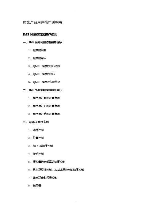
时光产品用户操作说明书IMS伺服控制器操作使用一.IMS系列伺服控制器的程序1.程序的编制2.程序的写入3.QMCL程序的运行选择4.QMCL程序的运行5.QMCL程序运行的终止二.IMS系列伺服控制器的运行1.程序运行前的注意事项2.程序运行时的注意事项3.程序运行后的注意事项三.QMCL程序实例1.速度控制2.位置控制3.加/ 减速度控制4.转矩控制5.模拟量给定频率的速度控制6.具有正反转控制、加减速度控制的速度控制7.输出灯定时闪烁控制8.结束语一.IMS系列伺服控制器的程序●关于QMCLQMCL: 由“Quick Motion Control Language”的首字母组成。
是本公司开发的专用于IMS系列伺服控制器的电机运动控制语言。
●电机的运行IMS系列伺服控制器必须运行「QMCL」程序,才能控制被控电机的运转。
1.程序的编制「QMCL」由「语言代码」和为直接进行电机控制的「中间代码」组成的。
所谓语言代码,例如HZP(设定指令频率),是在用QMCL编译器软件编程时使用的语言。
程序的内容可一目了然。
所谓中间代码,上例中的设定指令频率HZP用E1来表示,,是对IMS系列伺服控制器直接写入程序时使用的代码。
以上有关QMCL具体的说明和编制方法请详见[QMCL语言说明书]。
请注意在400V级11kW以上(包括11kW)的IMS伺服控制器的QMCL程序的起始,务必加入如下几条程序,否则会发生欠压报警。
POKE $F0FD $40 ;欠压报警无效TIC1=1250L00 JNE L00 TIC1 ;延时3秒左右POKE $F0FD 0 ;欠压报警有效2.程序的写入经过QMCL编译软件的编译就可以将语言代码转化成中间代码(自动生成后缀为.q的文件)。
中间代码可以通过键盘显示器直接键入控制器内,也可以通过通信口用PC机将编译时自动生成后缀为.q的文件下传到控制器内的RAM区(QMCL编译软件包含有下传功能)。
KW普乐特控制器说明书

电脑控制器使用说明电脑控制器主要功能有监视压缩机运行状态,控制压缩机,保护压缩机,监控保养零件等。
电脑控制器是空压机的控制核心,对机组正常运行起关键作用,故请用户使用前详细阅读本控制器使用说明。
一、基本操作1、按键说明排气温度:80C供压:0.60MPa运行状态:设备已停止0秒机旁ON M图1ON——起动键:按此键可起动电机运行OFF——停机键:按此键可停止电机运行M——设定键:修改完数据后,按此键确认数据存储输入——上移键:数据修改时,按此键上翻修改该数位;在菜单选择时作为选择键。
——下移键:数据修改时,按此键下翻修改该数位;在菜单选择时作为选择键。
——移位键/确认键:修改数据时,此键作为移位键;在菜单选择时作为确定键。
RT——返回键/复位键:在菜单操作时作为返回键返回上一级菜单;故障停机时,按此键复位。
2、状态显示与操作机组通电后显示如下界面:欢迎使用*****杆压缩机5秒后显示以下主界面:排气温度:20℃供气压力:运行状态:设备已停止机旁按“”进入以下菜单选择界面:运行参数日历用户参数厂家参数a、运行参数查看按“”或“”移动黑色滚动条到“运行参数”菜单后,按确认键“”后弹出下一级菜单:主、风机电流运行总时间本次运行时间维护参数再按“”弹出电流(A):R S T主机:风机:如为最后一级菜单,界面不会出现黑色滚动条,按返回键“RT”返回上级菜单或主界面。
如在某一界面停止操作,数秒钟后自动返回主界面。
用“”、“”移动键、确认键“”和返回键“RT”根据上述方法可完全观察到运行时间、本次运行时间、维护参数、历史故障、出厂日期、现场故障等运行参数并返回到上级菜单。
b、日历时间按“”或“”移动黑色滚动条到“日历”菜单后,按确认键“”后弹出现行时间2004年2月22日星期012时46分59秒在停机状态下可对日期、时间进行调整,操作方法为:按“”或“”移动黑色滚动条到需修改的参数项后按确定键“”后出现闪烁位,此时“”和“”键变为上翻和下翻键修改当前位,“”变为移位键移动修改位。
PreSonus ATOM SQ 控制器使用指南说明书

Production and Performance Pad ControllerGetting Started • Erste Schritte • Cómo empezar • Pour commencer • 开始登录, 注册序列号。
要先将其连接到可用的电脑USB接口。
无需安装驱动器。
连接到Studio One和Ableton Live后,特种作业会自动进行。
更多信息请访问, 阅读ATOM SQ操作手册。
™Screen Controls • Controles de la pantalla • Screen-Bedienelemente • Commandes d‘écran • 屏幕控制。
Use the encoder to change parameter values. Press the button above or below aparameter to change the value. Use the left and right arrow buttons to go to the next orprevious screen for any of the menu options.Utilice el codificador para cambiar los valores de los parámetros. Pulse el botón encimao debajo de un parámetro para cambiar el valor. Utilice los botones de flecha izquierda yderecha para ir a la pantalla siguiente o anterior para cualquiera de las opciones de menúÄndern Sie Parameter-Werte mit dem Endlosregler. Drücken Sie die Taste über oder untereinem Parameter, um den Wert zu ändern. Mit den rechten und linken Pfeiltasten blätternSie in den Menüoptionen vor- und zurück.Utilisez l’encodeur pour changer les valeurs de paramètre. Pressez la touche au-dessus ouau-dessous d’un paramètre pour changer de valeur. Utilisez les touches flèches gauche etdroite pour passer à l’écran précédent ou suivant de n’importe quelle option du menu使用编码器更改参数。
(整理)PROMOS控制系统原理.

一、PROMOS控制系统原理1 工作原理:PROMOS系统上电后,控制器首先对急停和电话等非智能部件进行初始化查询,然后根据返回的信息,判断安全回路是否正常;对非智能部件初始化结束后,接着进行智能部件的初始化,以设置每一个I/O口的数据类型,如:开关量、模拟量、或频率量。
初始化完成以后,控制器每隔35 ms对非智能部件进行一次查询,并不断对智能部件进行令牌式查询。
智能部件通过I/O口采集的信息,首先由智能部件进行预处理,然后传给控制器,由控制器进行处理,决定是否进行某种动作,然后将指令传给智能部件,由智能部件控制执行单元来完成控制器的指令。
2 硬件说明KJF21A型控制器1 概述KJF21A型控制器是KJ50型PROMOS监控系统中的核心产品,是一种多功能可编程通用型控制器。
1.3 防爆型式:Ex ibI(+150℃)1.4 关联设备:KDW10型矿用直流稳压电源。
1.5 配接设备为:KJF21型控制器KJJ10型控制接口KJK3型系列辅助控制器KTK1型系列扩音电话KPG3型系列急停开关KFD1型系列线路终端KPA1型按钮KPG2型开关KZD2型电控阀等等2 组成结构与工作原理2.1 外部结构其产品外形结构见图1控制器外形图(4)磁感应开关指示灯(5)外围设备错误指示灯(6)安全回路状态指示灯(7)维修状态指示灯(8)单机状态指示灯(9)被控设备运行指示灯(10)预警按钮(15)3#单台启停旋钮(16)备用单台启停旋钮(17)1#单台启停旋钮(18)2#单台启停旋钮(19)Linie右(20)AST口(21)Linie左(22)集中控制开关(23)控制方式开关(24)磁感应开关2.2内部结构2.CMA卡4.LINIE卡15.LINIE卡2X1.AST线NF语音通信功能X2.NF语音内部通信插座X3.前面板通信总线插座X4.PS2305S电源插座X5.AST2,AST3电源插座X6.PS2300电源AMP插座X7.AST1和LINIE外部电源插座X8.LINIE1左插座X9.LINIE1右插座X10.LINIE2左插座X11.LINIE2右插座X12.AST1插座X13.AST2插座X14.AST3插座X15.20MA串口A(SIO1)插座X16.20MA串口B(SIO2)插座S2 PS2501模块和AST光缆连接开关H1-H10 发光指示灯2.2.3 串行接口:控制器有两个串行接口SIOⅠ(B)和SIOⅡ(A),按通讯方式可选择20mA,通信距离A口:1000M,B口:2000M20mA外系统设备接口2.3.2 通讯波特率的设定KDW10型矿用直流稳压电源1 概述1.1KDW10型矿用直流稳压电源(以下简称电源)是PROMOS系统中的关键产品,为PROMOS系统提供本安电源,适用于煤矿井下的有甲烷和煤尘爆炸性危险的环境中,其防爆型式为:矿用隔爆兼本安型。
德国海因茨曼速度控制器操作说明
A 量参数设置为0 ,此时只使用修正参数
620x 。只根据供油量(即,负载)变化进 行修正时,须将所有在转速参数设置为0 ,
N 此时只使用修正参数62x0 。
6) 出厂时,所有修正参数均设为100%。
Z N 7) 设置参数4100PIDMapOn = 1 ,则启用
该修正曲面功能。
Slide33
© Heinzmann 2007
德国海因茨曼电调操作培训
E IN
A
Z
N N
Slide1
© Heinzmann 2007
1 电路连接检查
E I N • 确认转速传感器、执行器、控制器各处接
A 头的可靠连接,并按照应用图纸检查电路
连接。
N 注意:转速传感器和执行器的屏蔽线一定
要按照接线图接好。
ZN
Slide2
© Heinzmann 2007
Z示。 N
Slide23
© Heinzmann 2007
• B. 设定稳态运行时的转速变化对PID参数
E I N 值的修正。
A ⑴对于飞轮转动惯量比较小的发动机,负载 变化就容易引起转速的波动,其中一个可
N 能的原因就是,发动机稳态运行时,所需
要设置的比例参数值比较小,很难在负载
Z N 变化时稳定控制住发动机,为此,海茵茨
N 高,这也就意味着控制器的动态响应参数也 A 要提高。当发动机带有负载后,发动机的加
速特性降低了,这也意味着需要提高相应的
N 动态响应参数。 通常是在额定转速和空载的情况下,设
Z N 定好PID参数的, 有时候我们希望,在怠速时
能减小PID参数值,而在加载后增大参数值。
Slide28
© Heinzmann 2007
勤牛多功能控制器用户手册 说明书
多功能控制器用户手册(技术开发文档)文档版本:V1.002发布日期:2021/04/12版权所有© 勤牛创智科技有限公司2021。
保留一切权利。
非经本公司书面许可,任何单位和个人不得擅自摘抄、复制本文档内容的部分或全部,并不得以任何形式传播。
免责申明在法律允许的最大范围内,本手册所描述的产品(含其硬件、软件、固件等)均“按照现状”提供,可能存在瑕疵、错误或故障,勤牛创智不提供任何形式的明示或默示保证,亦不对使用本手册或使用本公司产品导致的任何特殊、偶然或间接的损害进行赔偿。
在使用本产品前详细阅读本使用手册及网上发布的相关技术文档并了解相关信息,确保在充分了解产品相关知识的前提下使用本产品。
本产品的使用者有责任确保遵循相关国家的切实可行的法律法规,确保在勤牛创智机械臂的使用中不存在任何重大危险。
版本修订说明北京勤牛创智科技有限公司地址:北京市海淀区清华东路16 号3号楼中关村能源与安全科技园1603 室网址:目录1. 产品简介....................................................................................................................................................................... - 6 -1.1多功能控制器概述 .......................................................................................................................................... - 6 -1.2控制器外观接口总览...................................................................................................................................... - 6 -2. 控制器接口功能介绍................................................................................................................................................ - 8 -2.1状态指示灯........................................................................................................................................................ - 8 -2.2 OLED屏幕.......................................................................................................................................................... - 8 -2.3导航键 ................................................................................................................................................................. - 8 -2.4第7轴步进电机接口...................................................................................................................................... - 9 -2.5第7轴复位开关接口....................................................................................................................................- 10 -2.6电源输出接口..................................................................................................................................................- 10 -2.7串口通信接口..................................................................................................................................................- 10 -2.8 RS485通信接口 .............................................................................................................................................- 11 -2.9串口通信接口..................................................................................................................................................- 11 -2.10 PWM信号输出接口...................................................................................................................................- 12 -2.11 I/O接口..........................................................................................................................................................- 12 -2.12扩展通信接口...............................................................................................................................................- 13 -2.13 TF卡插槽.......................................................................................................................................................- 13 -3.控制器快速入门..........................................................................................................................................................- 14 -2.1硬件连接...........................................................................................................................................................- 14 -2.2气泵及舵机使用.............................................................................................................................................- 15 -2.3滑轨及传送带使用 ........................................................................................................................................- 16 -2.4执行脱机文件..................................................................................................................................................- 17 -⚫主界面....................................................................................................................................................- 17 - ⚫一级菜单 ...............................................................................................................................................- 17 - ⚫执行“test.gcode”.................................................................................................................................- 18 - ⚫暂停运行 ...............................................................................................................................................- 19 - ⚫停止运行 ...............................................................................................................................................- 19 -2.5脱机文件下载..................................................................................................................................................- 20 -2.6蓝牙通信...........................................................................................................................................................- 22 -⚫示教器蓝牙连接..................................................................................................................................- 22 - ⚫手机APP蓝牙连接............................................................................................................................- 24 - ⚫电脑蓝牙连接......................................................................................................................................- 26 - ⚫修改蓝牙名称与密码 ........................................................................................................................- 28 -2.7 RS485通信 ......................................................................................................................................................- 30 -⚫RS485模式设置..................................................................................................................................- 31 - ⚫配置地址 ...............................................................................................................................................- 32 - ⚫硬件连接 ...............................................................................................................................................- 33 - ⚫多机控制 ...............................................................................................................................................- 33 -2.8 WIFI通信..........................................................................................................................................................- 34 -2.9 串口通信..........................................................................................................................................................- 35 -2.10 I/O引脚触发.................................................................................................................................................- 37 -3.控制器固件升级..........................................................................................................................................................- 38 -3.1控制器固件升级步骤:...............................................................................................................................- 38 -附件一:指令表.............................................................................................................................................................- 39 -1. 产品简介1.1多功能控制器概述多功能控制器(以下简称“控制器”)是Mirobot机械臂的重要配件。
魅玛轻型迷你PTZ控制器RM-LP5用户手册说明书
Mini PTZ Controller RM-LP5User ManualParameters & Specs Communication & Control Interface Camera Control or Operation Control Signal FormatPower Supply and ConsumptionPhysical & Others Description of Button & Knob FunctionInterface Function and Connection Diagram Upgrade Interface RS422/RS485 Interface RS232 Interface LAN Interface12V DC Power InterfaceSystem Menu Operation Instructions System Menu Function Explanation Keyboard System Menu System Setting Comm Setting Ethernet SettingPassword SettingSystem Menu Guide Products DimensionsContent2 2 2 2223 7 7788910 10 10 10 11 11 12 12 13④⑤⑪⑮①This Rotation Knob which was to adjustment the Camera Exposure Parameter or Red Gain Value, Turn Right Rotation was to changed the valued Increased, Turn Left Rotation was changed the Valued Decreased.②This Rotation Knob which was to adjustment the Camera Exposure Parameter or Blue Gain Value, Turn Right Rotation was to changed the valued Increased, Turn Left Rotation was changed the Valued Decreased.③This Rotation Knob which was to adjustment the Camera Exposure Parameter, Turn Right Rotation was to changed the valued Increased, Turn Left Rotation was changed the Valued Decreased.④LED Display, Real-time display of items and parameter values of adjusted by " knob ①".⑤LED Display, Real-time display of items and parameter values of adjusted by " knob ②".⑥LED Display, Real-time display of items and parameter values of adjusted by " knob ③".⑦Zoom Bridge KeyIt is used to control the camera to Zoom In/Out, for example, press the TELE end of the bridge key, the camera will Zoom in the TELE direction object, When you Press with more Large Pressure, then the Zoom Speed changed more Faster.⑧ Focus Function ZoonWhen the Backlight of [AUTO]Button is Light up, it means that the current focusing mode is the automatic; When the Backlight of [AUTO] Button is Light Off, it means that Current Focus Mode is changed to Manual. User can Press this button to switch the mode.[OPT key] is used to trigger the single focus of the camera.At the same time, the camera enters the one-shot auto focus mode.⑨PTZ Speed Adjustment KnobThis knob is used to adjust the speed of Camera Pan, Tlit and Zoom, with a total of 7 gears.The Current Gear will be display at Led Display. The Gear Value is more small then the pan/tilt rotation speed or the zoom speed of the camera controlled by the keyboard will be more Slowly.⑩ 2-Aixs JoystickThe joystick supports control camera to Up/Down, Left and Right movement. When the camera or keyboard menu is opened, the joystick is used to control the menu cursor Up/Down,Left/Right movement and modify parameters.⑪ Channel Button Zone[ CAM1 ] to [ CAM5 ] are shortcut keys for camera channels, which can be Freely switched and selected according to your need. When you select any camera channel, the backlight of the corresponding camera channel will be light up in green, and all the parameters and settings of the keyboard will be changed to the current Channel.Note: The communication parameters (address ID, protocol, baud rate, IP address, port number, etc.) of each channel can be set individually.Support mixed use of multiple protocols through different channel.⑫ Presets Function Zone●[ Number Keys ]SETING PRESETS :Long Press and hold the number key for 2 seconds (such as [Number key 1], when the screen displays "Set Preset 1” means that preset 1 has been saved) CALL PRESETS :Short press the preset number to be call Presets, (for example, [Number key 1],when you press the [Number key 1]the screen displays "Show Preset 1", it means that preset 1 has been call).●[ RESET Key ]TO BE CLEAR THE PRESET SETTINGPress[RESET key]+[Number key]to clear the preset position setting. After pressing the [RESET key], the green backlight starts to flash, Then press the preset number that needs to be cleared, (for example,[RESET]+ [Number key 1], at this time, the green Backlight of button of the [RESET key]stops flashing, and at the same time, “Reset Preset 1” is displayed on the screen, which means that preset 1 has been cleared.⑬ FOCUS KnobThis Knobs is using to adjustment camera’s focal length, Rotation right direction is adjustment focus length near, Rotation Left direction is adjustment focus length Far; (When User using this function, the keyboard’s Focus mode will be changed to Manual, It wasn’t available on AUTO Mode).⑭ Function Key Zone●[Menu Key]This key is to Turn ON/OFF Camera Menu, Long Press with 3secs will turn on Keyboard system Menu.●[AE MODE Key]This key is used to change the automatic exposure mode of the camera. Each time is pressed, the camera changes to different exposure mode. Under in difference of exposure mode, the corresponding functions of Knob 1, Knob 2 and Knob 3 are different. It is shown in real time on the display at the right of the knob.● [ WB MODE Key ]This Key is used to changed the White Balance of the camera. Each Time is pressed, the camera will be changed to different WB Mode.Under in difference ofWB mode, the corresponding functions of Knob 1, Knob 2 are different.The specific functions of the knobs are shown in Table 2:●[ Fn Keys ]This key is reserved for adding custom functions.The factory default state is: short press this key to send the command to enter theSub-menu of the camera, long press this key for 3 seconds to back Home Position of Camera.⑮ LED DISPLAYIt is used to display the current status information & Setting information of the keyboard in real time (including IP address, Port number, serial port address, communication protocol, Baud Rate and other information) and keyboard menu,the brightness of the display can be set through the keyboard menu.White Balance ModeKnob 1Knob 2AutoNOT USED NOT USED Manual Red GainBlue GainTable 2The interface is for upgrade of Hardware of keyboard by Laptop. Using Micro USB Cable direct connection with PC, And Upgrade by our upgrade tools software.This Interface is using to Connection with Camera by RS422 or RS485,detail connection diagram as follows pictures:③ RS232 InterfaceThis Interface is using to connection with Camera through RS232, detailThe LAN Interface is using for connection with Network switch or others.Network PTZ Camera, detail connection diagram as follows:●This interface is the Power supply interface, you can direct connection it with Power adapter; please don’t using non-original Power adapter.⑤ DC Power Supply Interface● Connect with multiple cameras by LAN interface detail connection diagram as follows:(When connecting multiple cameras, you need to set the IP of each camera separately1.Long Press [ MENU ] with 3secs will turn on Keyboard system Menu;2.The joystick swings up and down: control the system menu cursor to move up and down / change the parameters of the current menu item;3.The Joystick swings Right: enter the current menu item / save and exit the current menu item;4.The Joystick swings Left: Exist current Menu item/ No Saved and Exit current Menu item;5.Press [ MENU ]to exist System Menu;6.Press the number keys[0]~[9]: input numerical value (only valid for menu items that need to input numerical value). example IP Address or Port number setting.7.When the current value is number input, the green backlight of [CAM1]~[CAM5] is Light on, and at this time [CAM1]~[CAM5] Corresponds to the numbers 6~0 on the silk screen above the buttons.SYSTEM MENU 1.Long Press [ MENU ] with 3 secs will turn on Keyboard system Menu.2.The joystick swings up and down to control the menu cursor to move up and down SYSTEM SETTING The joystick swings up and down the Cursor to [ System Setting ], then Movement right to enter System Setting menu.● [ Language ]The Joystick swings up/down to [Language], then Movement right to enter setting. The Joystick swing up/down can changed the current Parameters setting, Swing the joystick to the right to save the current parameters and exit the language settingstate. The following menus operate setting is same.Optional Language: Chinese, English; other languages can be customized and developed according to customer needs.● [ LED Display Brigtness ]Change the brightness of the LED display: Low, Normal, High.● [ Automatically Standby ]Set the keyboard to automatically enter standby mode without any operation within a limited time.Select-able: Off, 1 minute, 2 minutes, 5 minutes, 10 minutes, 20 minutes, 30 minutes, 60 minutes.● [ Itself IP ]To setting Keyboard itself IP Address / Port Number, default IP is 192.168.1.88, default Port 52381.System Menu Operation & Explanation 1. System Setting 2. COMM Setting 3. Ethernet Setting 4. Password Setting1. Language : English2. LED Display Brigtness: Normal3. Automatically Standby: Off4. Itself IP: 192.168.001.0885. Itself Port: 523816. Factory default Setting7. About Keyboard●[ Factory default Setting ]To change the Keyboard restore to Factory default setting.● [ About Keyboard ]To review the relevant information of the keyboard, including: keyboard model, Firmware version, factory S/N and other information.●[ Address ]To set the serial communication address of the corresponding channel.If the current communication protocol is VISCA, the communication address can be selected from 1~7. If the current communication protocol is PELCO-D/P,The communication address can be selected from 1~255.●[ Baud Rate ]To set the serial communication Baud Rate of the corresponding channel.Available in: 2400, 4800, 9600, 19200, 38400bps.●[ Protocol ]To set the Serial communication Protocol of the corresponding channel ( Including Serial Communication Protocol and Internet Communication Protocol).Available in: VISCA, PELCO P/D, UDP .ETHERNET SETTINGTo move the cursor to [ Ethernet Setting ], then Movement right to enter Ethernet Setting:●[ Channel ]The available channels CAM1~5 correspond to the buttons [CAM1]~[CAM5].●[ Cam IP ]To set the Cam IP of the corresponding channel, which can be directly input through the number keys. When the number of input digits reaches 3, the cursor will automatically Jump to the next entry.●[ Port ]To set the UDP Port of the corresponding channel, it depend for the UDP Port 1. Channel: CAM1 2. Cam IP: 192.168.1.1623. Port: 52381PASSWORD SETTINGTo move the cursor to [ Password Setting ], then Movement right to enter Password :●[ Using Password ]How to Using the Password Function:To changed the Password setting is Enable;When the password function is Enable, a password is required to enter the menu.The default password is: 8888●[ Modify Password ]The user can change the password by himself. If the password is not changed, the password is the default password.Warning: Please use this function with caution. If the product cannot be used normally due to the password set by the customer, the manufacturer does not assume any responsibility.1. Using Password: Enabled2. Modify PasswordSYSTEM MENU GUIDE nguage: Chinese, EnglishProducts Dimensions The size for Mini Pro PTZ Controller is as below:(Unit of length: mm)。
Pulse MIG R系列说明书
30A 32A ≥2.5mm2 50mm2 ≥2.5mm2
50A 63A ≥6mm2 70mm2 ≥6mm2
注:上表中保险丝和断路器的容量仅供参考。
·7·
3、控制和接口 焊机前后面板控制与接口如图 3-1 所示。
5 3
4
6
7
1
2
9
8
(1)外设控制插座 X3 (3)程序升级下载口 X4 (5)输入电缆 (7)保险丝管 (9)加热电源插座 X5
合金类型
保护气体
·11·
MIG/MAG 脉冲焊接
MIG/MAG 一元化 直流焊接
铝镁合金 纯铝
铝硅合金
LF2--LF16、5005、 5052、5183、5356
Φ1.0、 Φ1.2、 Φ1.6
L1—L5、 1060、1035、1100、
1200、1370
100%Ar
LT1、4A11、 4043、4047
·1·
安全注意事项
一般安全注意事项 请务必遵守本说明书规定的注意事项,否则可能发生事故。 输入电源的设计施工、安装场地的选择、高压气体的使用等,
请按照相关标准和规定进行。 无关人员请勿进入焊接作业场所内。 请有专业资格的人员对焊机进行安装、检修、保养及使用。 不得将本焊机用于焊接以外的用途(如充电、加热、管道解冻
等等)。 如果地面不平,要注意防止焊机倾倒。
防止触电造成电击或灼伤 请勿接触带电部位。 请专业电气人员用规定截面的铜导线将焊机接地。 请专业电气人员用规定截面的铜导线将焊机接入电源,绝缘护
套不得破损。 在潮湿、活动受限处作业时,要确保身体与母材之间的绝缘。 高空作业时,请使用安全网。 不用时,请关闭输入电源。
- 1、下载文档前请自行甄别文档内容的完整性,平台不提供额外的编辑、内容补充、找答案等附加服务。
- 2、"仅部分预览"的文档,不可在线预览部分如存在完整性等问题,可反馈申请退款(可完整预览的文档不适用该条件!)。
- 3、如文档侵犯您的权益,请联系客服反馈,我们会尽快为您处理(人工客服工作时间:9:00-18:30)。
①LED显示:8个LED,用于操作及金属信号显示
②操作键:+,-,F用于操作及设置
③“Reset(复位)”功能键:金属或故障信号发生后,手动复位
④“T est(测试)”功能键:金属检测器功能测试
⑤“Fault(故障)”指示灯:出现故障或错误时便闪烁
⑥“Metal(金属)”指示灯:若探测到金属灯会亮
一、灵敏度的设置:
按下“+”或“-”键可显示目前的灵敏度
再次按下“+”或“-”键,可提高或降低一级灵敏度下图显示了灵敏度已被提高一级。
然后按下“F”键,可保存所选的灵敏度。
如果5秒钟后仍未按下“F”键,控制器会恢复原有灵敏度设置。
如图所示,LED 8 不停闪烁,则表示目前产品为8。
按下“F”键后,产品更换程序被激活。
界面显示变为操作界面。
已选产品8的LED 熄灭,其他LED亮。
再次按下“+”或“-”键,可选择另一产品。
产品6被选中,则LED 6熄灭。
若要更换成选中的产品,则按下“F”键。
如果5秒钟内“F”键未被再次按下,将保留最初设置。
按下“F”键约3秒,产品学习程序被激活。
控制显示发生变化,3个连着的LED灯将从左自右不停的闪烁。
一段时间(约1分钟)内必须让产品屡次通过检测器,按“F”键结束学习程序。
如果控制器识别到产品角,则设置完成。
如果产品效应过大,没有检测到产品角,则相位角设置将不会改变。
如果“F”键在1分钟内没被再次按下,学习程序将自动终止(所有产品数据将保持不变)。
中止学习程序,请按“Reset”键。
所选产品的相位角设置将被自动恢复。