D20ME主板用户手册
Optoma HD20 用户手册说明书

Optoma factory reset. Optoma projector default password.
able of contentsTable of Contents ...................................................................................1Usage Notice ..........................................................................................2Safety Information .........................................................................................2Precautions....................................................................................................3Eye Safety Warnings ............................... Inhaltszusammenfassung zur Seite Nr. 2 sage otice Safety Information The lightning fl ash with arrow head within an equilateral triangle is intended to alert the user to the presence of uninsulated “dangerous voltage” within the product’s enclosure that may be of suffi cient magnitude to constitute a risk of electric shock to persons. The exclamation point within an equilateral triangle is intended to alert the user to the presence of important operating and maintenance (servicing) instructions in the literature accompanying the Inhaltszusammenfassung zur Seite Nr. 3 sage otice Precautions Please follow all warnings, precautions and maintenance as recommended in this user’s guide. ▀■ Warning- Do not look into the projector’s lens when the lamp is on. The bright light may hurt your eyes. ▀■ Warning- To reduce the risk of fi re or electric shock, do not expose this projector to rain or moisture. ▀■ Warning- Please do not open or disassemble the projector as this may cause electric shock. ▀■ Warning- When replacing the lamp, please allow the unit to c Inhaltszusammenfassung zur Seite Nr. 4 sage otice Do: Turn off and unplug the power plug from the AC outlet before cleaning the product. Use a soft dry cloth with mild detergent to clean the display housing. Disconnect the power plug from AC outlet if the product is not being used for a long period of time. Do not: Block the slots and openings on the unit provided for ventilation. Use abrasive cleaners, waxes or solvents to clean the unit. Use under the following conditions: - In extremely hot, cold or humid Inhaltszusammenfassung zur Seite Nr. 5 sage otice Eye Safety Warnings ▀■ Avoid staring/facing directly into the projector beam at all times. Keep your back to the beam as much as possible. ▀■ When projector is used in a classroom, adequately supervise students when they are asked to point out something on the screen. ▀■ In order to minimize the lamp power, use room blinds to re- duce ambient light levels. 5 English Inhaltszusammenfassung zur Seite Nr. 6 ntroduction Package Overview Unpack and inspect the box contents to ensure all parts listed below are in the box. If something is missing, please contact your nearest customer service center. Power Cord 1.8m Projector with lens cap Lamp N Noottee Due to different applications in each country, 2 × AAA Batteries IR Remote Control some regions may have different accessories. Documentation : User’s Manual Warranty Card Quick Start Card WEEE Card (for EMEA only) 6 POWER Inhaltszusammenfassung zur Seite Nr. 7 POWER Y VIDEO SERVICE VGA/SCART/YPbPr 12V OUT HDMI 1 HDMI 2 Pb Pr SOURCE ntroduction Product Overview Main Unit 5 1 2 3 5 6 4 9 8 7 6 1. Control Panel 6. Tilt-Adjustment Feet 2. Zoom Ring 7. Security Bar 3. Focus Ring 8. Input / Output 4. Zoom Lens Connections 5. IR Receivers 9. Power Socket 7 English POWER SOURCE Inhaltszusammenfassung zur Seite Nr. 8 POWER ntroduction Control Panel 1 2 10 3 4 5 9 7 8 6 1. Source 2. Menu 3.
D20维护和使用手册
D20系列RTU软件使用及维护手册长春华信自动化工程有限公司二零零四年二月第一章D20系列RTU硬件组成D20 RTU系统组成D20系列RTU,硬件由以下几部分组成:●D20主机●D20的I/O模块●通讯单元●辅助电源一、D20主机1.机箱组成D20 M的机箱设计成VME-欧洲卡样式,由以下模块组成:♦D20 M主处理器板(一个平置的双倍欧洲卡槽口)♦D20电源(占三个立式欧洲卡槽口)♦D20M+SS接线板(7个RS232串口,1个维护口,2个HDLC口)机箱采用标准的槽口,提供电缆和串口的接口。
电源开关、测试点和指示灯都装在D20M模块的前面。
2.D20 M的通信接口包括●两个HDLC通信口,用于与外设I/O模块进行通信。
●两个RS-232 9600波特的维护口●七个面向字节的异步RS232通信口。
七个串行口是可编程的、并用于对SCADA/EMS主站的通信与/或对其它串行设备的通信,诸如智能仪表等等。
(1)HDLC口(×2):♦D20 LINK:RTU对D20外设I/O的内部通信♦串行链路:HDLC,250KBPS,RS-485对绞线对,变压器隔离,2线制,半双工,MANCHESTER编码,×.25格式的规约(2)WESMAINT 口♦维护与组态用♦RS232,9600波特,XON/OFF握手(3)七个RS232串行口:♦50至38400波特(可编程)♦TXD,RXD,CTS,RTS,DCD信号♦DB9连接器♦IRIG-B卫星时钟接口3.LED显示主板:♦RUN :绿,正常运行时闪♦HALT:红,起机时闪,正常运行时不亮;若一直亮,表示主板运行故障♦FAIL :红,起机时闪,正常运行时不亮;若一直亮,表示主板运行故障电源:♦-12V:绿♦+12V:绿♦+5V:绿♦+48V:绿背板:♦DS1:绿,+5V指示4.机械方面(1)尺寸♦D20 M的逻辑板:6.3"(16.3CM)×9.187"(23.35CM)——水平安装在D20 M机箱内♦D20 M的端子板:1.75"(4.4CM)×19"(48CM)×8.25"(21CM)[H×W×D](高×宽×深)(2)重量D20 M机箱总成,带有D20 M、D20电源及D20 M端子板,约5.5kg。
ME-20中文说明书
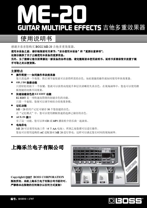
y 清洁本设备之前,请关闭电源并从插 座上拔下 AC 适配器连接线。
y 若怀疑您的地区可能发生雷击时,请 将电源插头拔掉。
y 如果使用不当,电池会发生爆炸或漏 液以及造成损害。为了使用安全,请 阅读并遵循以下事项(11 页) y 严格遵循电池安装操作说明,并确 认电池的正负极点是否正确。 y 避免将新旧电池混和使用,也请不 要将不同类型的电池混和使用。 y 设备如在一段时期内不使用,请将电池取出。 y 如果电池发生漏液,请使用柔软的擦布或纸 巾将电池槽中的液体擦干净,并装入新的电 池。为了避免液体腐蚀您的皮肤,请不要让 漏液接触到您的手或皮肤。千万小心不要使 漏液接触到眼睛,如果液体进入眼睛,立即 使用清水进行冲洗。 y 不要将电池与金属物体放在一起,如圆珠笔、 项链或发卡等。
y 与其他设备进行连接时,请关闭本设备的电 源。这样可以避免设备故障和音箱或其他设 备的损坏。
放置场所
y 请不要将本机直接曝晒在阳光下,或放在 热源旁边,或是放在密闭的车内空间,以 及其它高温物体旁。过高的温度容易造成 机体变形及变色。
y 请勿将橡胶、乙烯基等或类似物品长期放 置于设备上。这类物品可能会导致设备褪 色或外观的损坏。
y 使用后的电池必须遵循您居住区域的 安全处理条例进行处置。
上海乐兰电子有限公司
3
重要注意事项
除了阅读第 2-3 页的“安全使用本设备”,请阅读下文,并遵照执行。
电力供应:使用电池
y 请勿将本设备与其他由逆变器控制的设备 (如冰箱、洗衣机、微波炉或空调)或带有电 机的电器设备共用一个电源输出口。由于电 器设备使用方法不同,产生的电源噪音可能 会导致本设备故障或产生噪音。若无法使用 独立的电源插座,请在本设备与电源输出口 之间安装一个电源噪音滤波器。
大洋ME操作使用培训教程
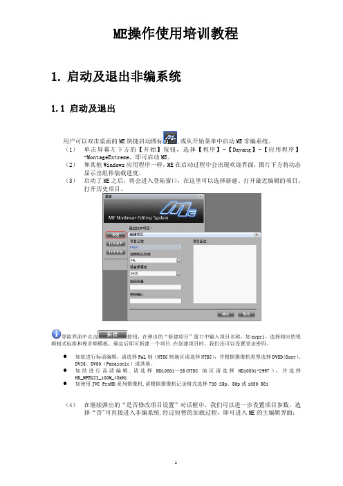
ME操作使用培训教程1.启动及退出非编系统1.1 启动及退出用户可以双击桌面的ME快捷启动图标,或从开始菜单中启动ME非编系统。
(1)单击屏幕左下方的【开始】按钮,选择【程序】-【Dayang】-【应用程序】-MontageExtreme,即可启动ME。
(2)和其他Windows应用程序一样,ME在启动过程中会出现欢迎界面,图片下方将动态显示出组件装载进度。
(3)启动了ME之后,将会进入登陆窗口,在这里可以选择新建、打开最近编辑的项目、打开历史项目。
登陆界面中点击按钮,在弹出的“新建项目”窗口中输入项目名称,如myprj,选择相应的视频制式标准和视音频模板,确定后即可新建一个项目.在创建项目时,我们还可以设置登录密码。
●如欲进行标清编辑,请选择PAL制(NTSC制地区请选择NTSC),并根据摄像机类型选择DVSD(Sony)、DV25、DV50(Panasonic)或其他。
●如欲进行高清编辑,请选择HD1080i—25(NTSC地区请选择HD1080i-2997),并选择HD_MPEG2I_100M_48kHz●如使用JVC ProHD系列摄像机,请根据摄像机记录格式选择720 25p、50p或1080 50i(4)在继续弹出的“是否修改项目设置”对话框中,我们可以进一步设置项目参数,选择“否"可直接进入非编系统.经过短暂的加载过程,即可进入ME的主编辑界面:当我们需要退出ME系统时,可以单击界面右上角“关闭”按钮,也可选择主菜单【文件】中的【退出】,在弹出的提示窗中确认退出.1.2 项目参数设置ME是基于项目管理的编辑产品,启动系统时需要选择或新建项目,设置相应的视频制式标准和视音频模板.初次启动项目时,系统会提示是否需要修改项目设置,选择“是”,则可进入项目参数设置窗口.在进入项目后也可以通过主菜单【系统】—【系统参数设置】—【项目参数设置】进入项目参数设置窗口。
通常需要关注视频比例设置、高标清上下变换方式、采集和合成的参数。
MD204L使用手册j简体中文版EW02CN02-081215

eviewmd204l用户手册第一章产品概述11功能12一般规格13各部分名称14外形尺寸及安装方法第二章编辑软件tp20021tp200概述211关于工程和画面212画面内容213tp200使用流程22编辑用户画面221创建工程222制作基本画面223md204l系统参数10224文本11225动态文本12226功能键画面跳转13227数据显示17228数据设定20229指示灯212210功能键开关量控制252211272212报警列表282213报警列表2923保存工程3024下载画面31第三章md204l操作方法31联机通讯3232切换画面3233系统口令3334修改数据3335开关量控制eviewmd204l用户手册第四章与plc的连接方法41三菱fx系列3742西门子s7200系列3843欧姆龙c系列3944光洋s系列4045施耐德neza系列4146台达dvp系列4247松下fp系列4348lgmasterk系列4449facon永宏系列eviewmd204l用户手册第一章产品概述11功能md204l是可编程序控制器的小型人机界面以文字或指示灯等形式监视修改plc内部寄存器或继电器的数值及状态
MONT20门机控制器用户手册_海浦蒙特_V1.1
门机控制器
用户手册
驱动异步&同步电机 单相 220-240V,0.4kW
版本:V1.1
前言
感谢您购买 MONT20 门机控制器! 本用户手册介绍了如何正确使用 MONT20 门机控制器,全面介绍了 MONT20 控制 器的安装配线、参数设置、故障对策、维护等详细信息。 在使用前,请务必认真阅读本用户手册。同时,请在完全理解产品的安全注意事项 后再使用该产品。
2.1 额定值 ................................................................................................................................................... 3 2.2 技术规格 ............................................................................................................................................... 3 2.3 尺寸与安装 ........................................................................................................................................... 5 2.4 安装场所要求....................................................................................................................................... 6 第三章 电气安装 ....................................................................................................................................................... 7 3.1 配线注意事项....................................................................................................................................... 7 3.2 电气要求 ............................................................................................................................................... 7 3.3 接口说明 .............................................................................................................................................10
ME主机说明书

Water Cooling Systems 709 709 冷却水系统709 Water Cooling Systems Index冷却水系统索引Water Cooling Systems 709-01冷却水系统1. General1. 概述Pipe systems vary considerably from plant to plant. The following schematic pipe diagrams are included here, for guidance, to illustrate the essential principles of the circuits and their correlation.管系随装置不同差异很大。
下面的管系示意图可作为指导且说明了管道的基本原理及他们间的相互联系。
For a specific plant, the correct details must be found in the piping diagrams supplied by the shipyard.对某一特定装置,其详细说明可查阅造船厂所给的管系管路图。
2. Seawater Cooling System (Plate 90901)2. 海水冷却系统(插图70901)Seawater is drawn up through the sea connection (1) by the seawater pump (2). From the pump, the water-flow is divided into three separate branches:海水经通海接头(1)由海水泵(2)抽取,泵排出的海水被分成三路:1. through the adjustable valve (3) direct to the main engine scavenge air cooler(s).1 经调节阀(3)直接到主机扫气空气冷却器;2. through the non-return valve (5) to the auxiliary engines2 经止回阀(5)到副机;3. through the adjustable valve (3) to the lub. oil cooler and jacket water cooler, which are connected in series.3 经调节阀(3)到串联联接的滑油冷却器和缸套水冷却器。
RTU培训-W

3
• WQ.MT860高精 度关口表
• WG.MT831多功 能电能表
• MDS-100数据采 集器
• 电量计费系统
惠安
产品外观
惠安
讲课内容:
第一部分:分布式RTU系统概述 第二部分:GR90RTU(D200及I/O)介绍 第三部分:ConfigPro组态软件及规约 第四部分:调试操作及常见故障 第五部分:电厂AGC&AVC介绍
此时需要立即更换电池。注意更换电池后需要重新下 装配置文件。 ● RUN 运行灯 由微处理器中的地址选通线所驱动 。表示微处理器在活动。 ● HALT 暂停 由输入至微处理机的HALT信号所驱 动。表示微处理器已被停机。 ● FAIL 故障 由一个被编程的信号所驱动。它表示 诊断程序正在运行或已出故障。
编写用户方程用于应用程序
惠安
惠安
LogicLinx™应用
AVC控制 VQC控制 顺序控制 五防闭锁 联锁和闭锁 配电自动化等
惠安
三 级
省 网 EMS/AVC 主
控
站
制
二 级 控
地调 EMS/AVC子
制
系统
一 级 控
省网直调电厂 AVC装置
所辖区域小电厂、变电
制
站AVC装置的调节
省网直调变电 站AVC装置
惠安
D200的特点
● 多CPU并行处理,实时多任务Psos ● 无硬盘设计 ,可靠性,抗病毒性 ● 直接上网,LAN/WAN网络通信 (网口:5/6/4RJ45) ● 多串口通信(7个RS232/每块CPU) ● 支持多种规约通信(国内/国际70多种) ● 可加载用户应用软件 (备自投;VQC;AVC,PLC )
WAN
Bridge/Router
- 1、下载文档前请自行甄别文档内容的完整性,平台不提供额外的编辑、内容补充、找答案等附加服务。
- 2、"仅部分预览"的文档,不可在线预览部分如存在完整性等问题,可反馈申请退款(可完整预览的文档不适用该条件!)。
- 3、如文档侵犯您的权益,请联系客服反馈,我们会尽快为您处理(人工客服工作时间:9:00-18:30)。
D20 MEQuick Start Guide994-0025-1.00-5General,Full Release© 2002, General Electric Canada, Inc. All rights reserved.The contents of this manual are the property of General Electric Canada, Inc. No part of this work may be reproduced or transmittedin any form or by any means, except as permitted in written license agreement with General Electric Canada, Inc. General Electric Canada, Inc. has made every reasonable attempt to ensure the completeness and accuracy of this document. However, the information contained in this manual is subject to change without notice, and does not represent a commitment on the part of General Electric Canada, Inc.GE Energy ServicesD20 MEQuick Start Guide994-0025 1.00 5 General2Full ReleaseD20 ME - Quick Start Guide ContentsIn this GuideThis Quick Start Guide contains the following topics:Topic See PageD20 ME Jumper Option Guide3 Introduction to Downloading Flash Code 5 Code Download – D20 ME - D20 Base 7 Code Download – D20 ME - CCU Base9D20 MEQuick Start Guide GE Energy ServicesGeneral 994-0025-1.00-5Full Release3D20 ME Jumper Option GuideD20 ME Board Layout DiagramThis diagram shows the location of some of the optional jumpers and components found on the 526-2004 to 526-2005 D20 ME cards.VME Jumper OptionsThe following tables summarize the jumper settings for each board function and position that it is installed in a CCU. Note:* Single Node D20 is the factory default configuration.Board FunctionJP1 Master / SlaveJP2VME Address Bits4 3 2 1JP3-1 RTC - SERCLOCKJP3-2 RTC - BTRC* Single Node D20 OUT IN IN IN IN OUT IN D200 Node #1 OUT IN IN IN OUT IN IN D200 Node #2 IN IN IN OUT IN IN OUT D200 Node #3 IN IN IN OUT OUT IN OUT D200 Node #4 IN INOUTINININ OUT D200 Node #5 IN IN OUT IN OUT IN OUT D200 Node #6 IN IN OUT OUT IN IN OUT D200 Node #7 IN IN OUT OUT OUT IN OUT D200 Node #8INOUTININININOUTContinued on next pageJP1JP4JP3JP2JP8BootROMGE Energy ServicesD20 MEQuick Start Guide994-0025 1.00 5 General4Full ReleaseD20 ME Jumper Option Guide, ContinuedJP1 - VME Control This jumper sets the Master or Slave role of the board on the VME bus. Note:Single-node (D20) systems are always set to MasterJP2 - VME AddressJP2 is a group of four jumpers that set the board’s VME bus address. The address should reflect the board location in a D200 CCU chassis. Example: T he board with address 1 will be the lead node, with nodes 2through 8 positioned to the right of the lead node. Note:Single Node D20s are set to address 0 (all jumpers IN)JP3-1 and JP3-2RTC OptionsThese two jumpers determine the R eal-T ime C lock (RTC) source for each D20 ME board in a CCU:• Single Node D20s and the first, or Lead, node of a D200 both use their internalclock.• Non-lead nodes of a D200 must synchronize their clocks to the lead node’sclock.JP4 - Watchdog This two-position jumper enables or disables the hardware Watchdog.Note:Never leave the Watchdog disabled during normal D20 ME operation.Jumper PositionFunctionpin 1 to 2 (center)Disables the hardware Watchdog. JP4Pin 1 = SLOWCK Pin 3 = /WDpin 3 to 2 (center)Enables the hardware Watchdog.JP8 – Battery BackupEnable/disableThe D20 ME card has two 3.6V Lithium batteries, TADIRAN TM TL-2150 or equivalent, to maintain NVRAM contents in the event of a power failure. Important: Disconnect the batteries if you are storing the board for extendedperiods of time.Jumper PositionFunctionpin 1 to 2 Disconnects the batteries from the NVRAM pin 3 to 2 Connects the batteries to the NVRAM JP8pins 4 to 5Always jumperedD20 MEQuick Start Guide GE Energy ServicesGeneral 994-0025-1.00-5Full Release5Introduction to Downloading Flash CodeIntroductionBefore you can put any D20M module into service, it must have a firmware application code loaded into its memory.All D20 ME boards use Flash memory to store their application code.Serial DownloadYou can load the Flash code file serially into the D20 ME’s memory using virtually any Windows communication software.Due to its availability, HyperTerminal will be used for the following procedureIdentify the D20 ME TypeThe D20 ME module type is determined by the version of BootROMinstalled, identifying how the module will be used. The type of module must be known before downloading flash code, as the download method depends on which BootROM is installed. Note:The /xx in the Label column is the software’s revision number.Module TypeBootROM LabelD20 ME D20 Base SBU0000/xx D20 ME CCUSBU0001/xxPrerequisites for Code DownloadThe following must be available before you can successfully load a flash code file into a D20 ME module:• Windows PC with HyperTerminal (or equivalent) communication softwareloaded.• The code file, in the Motorola S-record format, located on a local hard drive. Ifthe file is located on a network or floppy drive, the download may be significantly slower.− This file is typically named: down.shx• A WESMAINT cable for interconnecting the PC to the D20 ME WESMAINTfront-panel interface. • The D20 ME card must:− have its hardware option jumpers set, as per the previous section − be installed into a D20 or D200 chassis, ready to power-upContinued on next pageGE Energy ServicesD20 MEQuick Start Guide994-0025 1.00 5 General6Full ReleaseIntroduction to Downloading Flash Code, ContinuedUpgrading From D20M or 1 MB Flash D20 ME?Code files for previous D20M modules are created in a Binary format, usually called PROM.BIN files.• If you are upgrading a device running a D20M to use a D20 ME, you mustconvert the binary code file to a down.shx format before you can download it to Flash memory.• You must also use Config Pro to adjust the device’s Device Properties so thatthe new processor will run the converted code file.• If upgrading from a D20 ME with 1 MB flash (part # 526-2003), you will haveto modify the new configuration’s Device Properties to use the existing code file.Procedures for these conversions can be found in:994-0033 - D20 ME Installation & OperationSetup ProcedureThese steps will set up the equipment, ready to proceed with the following download procedures for D20 ME code filesStep ActionConfigure and Connect PC to D20 ME1Connect a WESMAINT cable from the PC’s Com port to the D20 ME’s front panel WESMAINT interface.2 Start Windows’ HyperTerminal communication software on thePC, and configure it as follows:− 9600 Bps − 8 bit − no parity− VT100 emulation−Xon/Xoff flow control enabledIdentify D20 ME Type3 If the D20 ME BootROM “type” is already known, jump ahead to:• Step 1 of D20 ME D20 Base Code Download procedure, or • Step 1 of D20 ME CCU Code Download procedureRestart the D20 ME (power off-on cycle) while watching the PCmonitor.If the first line of output text is: The Board type is: P149-0, D20 ME BootROM D20 Base 4 P130-0, GE Energy Services CCUME BootROMCCUD20 MEQuick Start Guide GE Energy ServicesGeneral 994-0025-1.00-5Full Release7Code Download – D20 ME - D20 BaseProcedure – D20 Base D20 METhe following steps demonstrate the serial download of a flash code file to a D20 Base type of D20 ME module.Step ActionD20 ME - D20 Base Code Download1 Restart the D20 ME, again.2As soon as messages are seen on the monitor, press ESCAPE within 5 seconds.Results: You will see a message like the one below, asking if youwish to mark the configuration “bad”.Type Y (or y) to default the configuration.Results: As shown below, the output of the D20 ME will confirmthat the configuration file is corrupt and may be cleared.P149-0 D20ME BOOTROM GE Energy Services BOOTROM: V1.28RELEASE: July 24, 2000 Power-up Diagnostics:> Boot ROM (U45)- pass > User RAM - pass > Configuring MemoryDo you want to mark this configurat1on as bad to get into the monitor? y/n - - >34 Press ENTER to bring up login dialog, then type westronic ENTERrd ENTER to log in.Results: After a Welcome message, the D20M> prompt displays. 5 Type sp to suspend all processes running on the D20 ME 6 Type erase to clear the Flash. This will take several seconds.Results: Flash Erased will be displayed when completedOptional Step 1: Speed-up communication to shorten download time.7 Type Baud 38400 ENTER (speeds up to 230.4Kbps, or lower speedsmay be chosen based on ambient EMI, cable length, PC limits etc.)Results: The monitor will now be communicating at 38.4Kbps 8 Configure HyperTerminal to communicate at the same speed,and reconnect to the 68K monitor.Continued on next pageGE Energy ServicesD20 MEQuick Start Guide994-0025 1.00 5 General8Full ReleaseCode Download – D20 ME - D20 Base, ContinuedProcedure – D20 Base D20 ME (continued)Step ActionOptional Step 2: Provide feedback during download9If the communication software you are using does not have any “progress indicator’, such as HyperTerminal, the enable echo to display the code file on your monitor as it is transferred.This option can be usually found in the communication settings or properties of the communication program.Note: Enabling echo may slow transfer slightly.Download Code File10 Type dl ENTER to put the D20 ME into the state where it is ready toreceive the downloadable code file 11 Click Transfer | Send Text File from menu barResults: A dialog box will open, prompting you to locate theDown.shx file that you wish to download. 12Select the correct file, and click Open to start the transferResults: The file transfer may take from less than 10 to over 30minutes, depending on communication speed selected.When complete, the D20M> prompt returns.13 Type el /p to display the error log. The D20M> prompt shouldreturn, indicating no errors found.Errors? Record error(s), and re-try download.If errors persist, contact GE Energy Services for support. 14 Type el /r to clear the error log, even if there are no errorsdisplayed in the previous step. 15 Type Boot to restart device.D20 MEQuick Start Guide GE Energy ServicesGeneral 994-0025-1.00-5Full Release9Code Download – D20 ME - CCU BaseProcedure – CCU D20 METhe following steps demonstrate the serial download of a flash code file to a CCU type of D20 ME module.Step ActionD20 ME CCU Code Download1 Restart the D20 ME, again.As soon as messages are seen on the monitor, press SPACEBARwithin 5 seconds.Results: You will see a message like the one below, asking ifyou wish to abort the Flash boot.Power-up DiagnosticsD20 ME Boot ROM (U45) – pass User RAM - pass NodeID (Z6) = 00 RAM size = 01536k NVRAM size = 00512k EPROM size = 02048k Single node CCUME …LNVRAM CRC calc – passSearching for local Configuration Control Block … not foundAre you sure you wish to abort the flash boot [y/n}?23 Type Y (or y) to abort the normal startup4 Press ENTER to bring up login dialog. Type westronic ENTER , thenrd ENTER to log in.Results: After a Welcome message, the D20MES> promptdisplays. 5 Type sp to suspend all processes running on the D20 ME 6 Type erase to clear the Flash. This will take several seconds.Results: The monitor will display, before returning the D20MES>prompt:Erasing FLASH memory <\ Checking FLASH contents... \Optional Step 1: Speed-up communication to shorten download time.7 Type Baud 38400 ENTER (speeds up to 230.4Kbps, or lower speedsmay be chosen based on ambient EMI, cable length, PC limits etc.)Results: The monitor will now be communicating at 38.4Kbps 8 Configure HyperTerminal to communicate at the same speed,and reconnect to the 68K monitor.Continued on next pageGE Energy ServicesD20 MEQuick Start Guide994-0025 1.00 5 General10Full ReleaseCode Download – D20 ME - CCU Base, ContinuedProcedure – CCU D20 ME (continued)Step Action Optional Step 2: Provide feedback during download9If the communication software you are using does not have any “progress indicator’, such as HyperTerminal, you can enable echo to visually display the code file on your monitor during transfer. This option can be usually found in the communication settings or properties of the communication program.Note: Enabling echo may slow transfer slightly.Download Code File10 Type dl ENTER to put the D20 ME into the state where it is ready toreceive the downloadable code file. 11 Click Transfer | Send Text File from menu barResults: A dialog box opens, prompting you to locate theDown.shx file that you wish to download. 12Select the correct file, and click Open to start the transferResults: The file transfer may take from less than 10 to over 40minutes, depending on communication speed selected.When complete, the D20M> prompt will return.13 Type el /p to display the error log. The D20ME> prompt shouldreturn, indicating no errors found.Errors? Record error(s), and re-try download.If errors persist, contact GE Energy Services for support. 14 Type el /r to ensure that log is clear, then type Boot to restart.Multi-NodeDownloadsD20 ME VME modules can be used in a multi-node VME system, i.e, a D200. The application code for each D20 ME module in a multi-node system can be either the same, or different for one or more of the modules.In either case, the procedure is the same as for a single node, just repeated as many times as there are nodes.Note: Do Not re-start (Boot) the multi-node system until All D20 ME cardshave been loaded.。