GS5810 1A同步整流芯片datasheet
BA5810FM中文资料
Optical disc ICs
BA5810FP/FM
CD/CD-ROM Driver Integrated Circuit
BA5810FP/FM
The BA5810FP is 5-channel driver designed for CD, CD-ROM, and other optical disc-related applications. The BA5810FP comprises a 4-channel BTL driver and a 1-channel reversible-motor drive. A stepping motor can be driven using 2 of the 4 channels. For optimum performance, PreVCC and power supply for power transistors operate independently (channels 1 − 2 and channels 3 − 4, respectively). In addition, a power-saving pin delivers power-saving functions.
10.0 6
300 − 0.5 − − −
V mV nA V V mA mA V/µs
BIAS=6V BIAS=6V
100KHz rectangular wave, 2Vp-p output
Fig.2 Fig.2 Fig.2 Fig.2 Fig.2 Fig.2 Fig.2 Fig.2
1.5
பைடு நூலகம்
V
Sum of upper side + lower side (IL=200mA)
恩智浦半导体TEA2093TS GreenChip同步整流控制器产品数据手册说明书
GreenChip同步整流控制器第1版——2022年6月7日产品数据手册1 简介TEA2093TS是针对开关电源的新一代同步整流器(SR)控制器IC系列中的一员。
它包含自适应栅极驱动器,以便在任意负载下达到最高效率。
TEA2093TS是一款专门用于非对称半桥反激式和标准反激式转换器次级侧同步整流的控制器IC。
它内置用于驱动SR MOSFET的检测级和驱动器级,对次级变压器绕组的输出进行整流。
TEA2093TS可以为具有低输出电压的电池充电应用或具有高侧整流的应用生成自己的供电电压。
TEA2093TS采用绝缘硅片(SOI)工艺制成。
2 特性和优势2.1 能效特性●自适应栅极驱动器,在任意负载下达到最高效率●空载运行时的典型电源电流低于200 μA2.2 应用特性●在低至0 V的宽输出电压范围内工作●能够处理高达120 V输入电压的漏检测引脚●对低输出电压工作自供电●对不使用辅助绕组的高侧整流自供电●使用标准和逻辑电平SR MOSFET●支持USB BC、USB PD和快充应用●TSOP6封装2.3 控制特性●自适应栅极驱动器,实现导通终止时的快速关闭●带有源栅极下拉的欠压锁定(UVLO)3 应用TEA2093TS适用于反激式电源。
在此类应用中,它可以驱动外部同步整流器MOSFET,这些MOSFET取代用于对变压器次级绕组上的电压进行整流的二极管。
它可用于所有需要高效率的电源,如:●充电器●电源适配器●非对称半桥反激式电源●具有极低和/或可变输出电压的反激式电源4 订购信息表1.订购信息型号封装名称说明版本TEA2093TS/1 TSOP6 塑料小型封装;6引脚SOT4575 标示表2.标记代码型号标记代码TEA2093TS/1 TEA20936 功能框图图1. TEA2093TS 功能框图导通调节关断调节V 和I参考欠压锁定 驱动器供电节能控制使能逻辑关闭7 引脚分布信息7.1 引脚分布图2.TEA2093TS引脚分布(SOT457)7.2 引脚说明表3.引脚说明符号引脚说明CAP 1 内部供电电压的电容输入GND 2 接地XV 3 外部电源输入GATE 4 SR MOSFET的栅极驱动器输出SOURCE 5 SR MOSFET的源极检测输入DRAIN 6 SR MOSFET的漏极检测输入8 功能说明8.1 简介TEA2093TS是一款用于非对称半桥反激式和标准反激式应用中的同步整流(SR)的控制器IC。
EG1190带使能降压开关电源控制芯片数据手册说明书
2. 描述
EG1190 一款宽电压范围降压型 DC-DC 电源管理芯片,内部集成使能开关控制、基准电源、误差放大器、 过热保护、限流保护、短路保护等功能,非常适合宽电压输入降压使用。
EG1190 零功耗使能控制,可以大大节省外围器件,更加适合电池场合使用,具有很高的方案性价比。
3. 应用领域
电动车转换器 摩托车转换器 快充电源 非隔离 DC-DC 逆变器系统 工业控制系统
引脚名称 GND VIN EN VIA FB VB HO VS IS
图 4-1. EG1190 管脚定义
I/O GND Power I O I O I
描述 芯片地(芯片背面) 芯片电源输入端。 使能脚,高电平有效,开关电源工作 输入电源电阻比例分压后输出 输出电压反馈输入 悬浮电源 高端输出 悬浮地。 MOS 峰值电流保护输入端口
ELECTRONIC GIANT
EG1190 芯片数据手册
带使能降压开关电源控制芯片
2020 ©屹晶微电子有限公司 版权所有
REV 1.0
屹晶微电子有限公司
EG1190 芯片数据手册 V1.1
带使能降压开关电源控制芯片
版本变更记录
版本号 V1.0 V1.1
日期 2020 年 03 月 03 日 2020 年 10 月 10 日
2020 ©屹晶微电子有限公司 版权所有
2/8
屹晶微电子有限公司
5. 内部电路图
EG1190 芯片数据手册 V1.1
带使能降压开关电源控制芯片
EN 2 VIA 3
GND 9
450K
15K
VREF=1.25V
OSC振荡器
电源管理 逻辑控制
FB 4
误差放大器
400W LDMOS S-带雷达应用电磁性功能芯片说明书

BLS9G3135L-400;BLS9G3135LS-400LDMOS S-band radar power transistorRev. 1 — 6 April 2017Product data sheet 1. Product profile1.1General description400W LDMOS power transistor for S-band radar applications in the frequency range from3.1 GHz to 3.5 GHz.Table 1.Typical performanceTypical RF performance at T case=25︒C; t p = 300 μs; δ = 10%; I Dq = 400 mA; in a class-AB democircuit.Test signal f V DS P L G pηD(GHz)(V)(W)(dB)(%)pulsed RF 3.1 to 3.53242512431.2Features and benefits⏹High efficiency⏹Excellent ruggedness⏹Designed for S-band operation⏹Excellent thermal stability⏹Easy power control⏹Integrated dual sided ESD protection enables excellent off-state isolation⏹High flexibility with respect to pulse formats⏹Internally matched for ease of use⏹Compliant to Directive 2002/95/EC, regarding Restriction of Hazardous Substances(RoHS)1.3Applications⏹S-band radar applications in the frequency range 3.1 GHz to3.5GHz2. Pinning informationTable 2.Pinning[1]Connected to flange.3. Ordering informationTable 3.Ordering informationType number PackageName Description Version BLS9G3135L-400-flanged ceramic package; 2mounting holes; 2leads SOT502ABLS9G3135LS-400-earless flanged ceramic package; 2leads SOT502B 4. Limiting valuesTable 4.Limiting valuesIn accordance with the Absolute Maximum Rating System (IEC 60134).Symbol Parameter Min Max UnitV DS drain-source voltage-65VV GS gate-source voltage-6+11VT stg storage temperature-65+150︒CT j junction temperature[1]-225︒C[1]Continuous use at maximum temperature will affect the reliability. For details refer to the online MTFcalculator.5. Thermal characteristics6. CharacteristicsTable 5.Thermal characteristicsSymbol ParameterConditionsTypUnitZ th(j-mb)transient thermal impedance from junction to mounting baseT case =85︒C; P L =400Wt p =100μs; δ = 10%0.11K/W t p =200μs; δ = 10%0.13K/W t p =300μs; δ = 10%0.15K/W t p =500μs; δ = 10%0.17K/W t p =1ms; δ = 10%0.18K/W t p =100μs; δ = 20%0.15K/WTable 6.DC characteristicsT j =25︒C unless otherwise specified.Symbol ParameterConditionsMin Typ Max Unit V (BR)DSS drain-source breakdown voltage V GS =0V; I D =4.5mA 65--V V GS(th)gate-source threshold voltage V DS =10 V; I D =450mA 1.52 3.1V I DSS drain leakage current V GS =0V; V DS =28V --4μA I DSX drain cut-off current V GS =V GS(th)+3.75 V; V DS =10V-85-A I GSS gate leakage current V GS =11V; V DS =0V --400nA g fs forward transconductance V DS =10V; I D =450mA - 4.2-S R DS(on)drain-source on-state resistanceV GS =V GS(th) + 3.75V; I D =15.75A-0.026-ΩTable 7.RF characteristicsTest signal: pulsed RF; t p = 300 μs; δ = 10%; RF performance at V DS =32V;I Dq =400mA; T case =25︒C; unless otherwise specified, in a class-AB production circuit.Symbol Parameter Conditions Min Typ Max Unit G p power gain P L =425W 1011-dB ηD drain efficiency P L =425W 4043-%RL ininput return loss P L =425W --6-dB P droop(pulse)pulse droop power P L =425W -0.150.50dB t r rise time P L =425W -650ns t f fall timeP L =425W-650ns P L(2dB)output power at 2 dB gain compression400--W7. Test information7.1Ruggedness in class-AB operationThe BLS9G3135L-400 and BLS9G3135LS-400 are capable of withstanding a loadmismatch corresponding to VSWR=10:1 through all phases under the followingconditions: V DS=32V; I Dq=400mA; P L=400W; t p = 300 μs; δ = 10%.7.2Impedance informationTable 8.Typical impedancef Z S Z L(GHz)(Ω)(Ω)3.14.122 - j8.679 1.206 - j4.2313.2 6.215 - j3.927 1.593 - j4.3963.34.334 - j3.313 1.885 - j4.2623.4 2.085 - j2.187 2.473 - j3.9153.5 1.976 - j2.700 2.313 - j3.1807.3Test circuit informationTable 9.List of componentsFor test circuit see Figure2.Component Description Value RemarksC1, C4multilayer ceramic chip capacitor10pF ATC100AC2multilayer ceramic chip capacitor 4.7μFC3, C8, C10multilayer ceramic chip capacitor1nF ATC100BC5, C6, C9multilayer ceramic chip capacitor10pF ATC800AC7, C11multilayer ceramic chip capacitor10μF, 50 V Murata: GRM55DR61H106KA88L C12electrolytic capacitor220μF, 63 VR1resistor5ΩSMD 06037.4Graphical data8. Package outlineFlanged ceramic package; 2 mounting holes; 2 leads SOT502AFig 8.Package outline SOT502AEarless flanged ceramic package; 2 leads SOT502BFig 9.Package outline SOT502B9. Handling informationTable 10.ESD sensitivityESD model ClassCharged Device Model (CDM); According to ANSI/ESDA/JEDEC standard JS-002C2A [1]Human Body Model (HBM); According to ANSI/ESDA/JEDEC standard JS-001 2 [2][1]CDM classification C2A is granted to any part that passes after exposure to an ESD pulse of 500V, but failsafter exposure to an ESD pulse of 750V.[2]HBM classification 2 is granted to any part that passes after exposure to an ESD pulse of 2000V, but failsafter exposure to an ESD pulse of 4000V.10. AbbreviationsTable 11.AbbreviationsAcronym DescriptionESD ElectroStatic DischargeLDMOS Laterally Diffused Metal-Oxide SemiconductorMTF Median Time to FailureS-band Short wave BandSMD Surface Mounted DeviceVSWR Voltage Standing-Wave Ratio11. Revision historyTable 12.Revision historyDocument ID Release date Data sheet status Change notice SupersedesBLS9G3135L-400_LS-400 v.120170406Product data sheet--12. Legal information12.1 Data sheet status[1]Please consult the most recently issued document before initiating or completing a design.[2]The term ‘short data sheet’ is explained in section “Definitions”.[3]The product status of device(s) described in this document may have changed since this document was published and may differ in case of multiple devices. The latest product statusinformation is available on the Internet at URL .12.2 DefinitionsDraft — The document is a draft version only. The content is still under internal review and subject to formal approval, which may result in modifications or additions. Ampleon does not give any representations or warranties as to the accuracy or completeness of information included herein and shall have no liability for the consequences of use of such information.Short data sheet — A short data sheet is an extract from a full data sheet with the same product type number(s) and title. A short data sheet is intended for quick reference only and should not be relied upon to contain detailed and full information. For detailed and full information see the relevant full data sheet, which is available on request via the local Ampleon sales office. In case of any inconsistency or conflict with the short data sheet, the full data sheet shall prevail.Product specification — The information and data provided in a Product data sheet shall define the specification of the product as agreed between Ampleon and its customer, unless Ampleon and customer have explicitly agreed otherwise in writing. In no event however, shall an agreement be valid in which the Ampleon product is deemed to offer functions and qualities beyond those described in the Product data sheet.12.3 DisclaimersLimited warranty and liability — Information in this document is believed to be accurate and reliable. However, Ampleon does not give any representations or warranties, expressed or implied, as to the accuracy or completeness of such information and shall have no liability for the consequences of use of such information. Ampleon takes no responsibility for the content in this document if provided by an information source outside of Ampleon.In no event shall Ampleon be liable for any indirect, incidental, punitive, special or consequential damages (including - without limitation - lost profits, lost savings, business interruption, costs related to the removal or replacement of any products or rework charges) whether or not such damages are based on tort (including negligence), warranty, breach of contract or any other legal theory.Notwithstanding any damages that customer might incur for any reason whatsoever, Ampleon’s aggregate and cumulative liability towards customer for the products described herein shall be limited in accordance with the Terms and conditions of commercial sale of Ampleon.Right to make changes — Ampleon reserves the right to make changes to information published in this document, including without limitation specifications and product descriptions, at any time and without notice. This document supersedes and replaces all information supplied prior to the publication hereof.Suitability for use — Ampleon products are not designed, authorized or warranted to be suitable for use in life support, life-critical or safety-critical systems or equipment, nor in applications where failure or malfunction of an Ampleon product can reasonably be expected to result in personal injury, death or severe property or environmental damage. Ampleon and its suppliers accept no liability for inclusion and/or use of Ampleon products in such equipment or applications and therefore such inclusion and/or use is at the customer’s own risk.Applications — Applications that are described herein for any of these products are for illustrative purposes only. Ampleon makes no representation or warranty that such applications will be suitable for the specified use without further testing or modification.Customers are responsible for the design and operation of their applications and products using Ampleon products, and Ampleon accepts no liability for any assistance with applications or customer product design. It is customer’s sole responsibility to determine whether the Ampleon product is suitable and fit for the customer’s applications and products planned, as well as for the planned application and use of customer’s third party customer(s). Customers should provide appropriate design and operating safeguards to minimize the risks associated with their applications and products.Ampleon does not accept any liability related to any default, damage, costs or problem which is based on any weakness or default in the customer’s applications or products, or the application or use by customer’s third party customer(s). Customer is responsible for doing all necessary testing for the customer’s applications and products using Ampleon products in order to avoid a default of the applications and the products or of the application or use by customer’s third party customer(s). Ampleon does not accept any liability in this respect.Limiting values — Stress above one or more limiting values (as defined in the Absolute Maximum Ratings System of IEC60134) will cause permanent damage to the device. Limiting values are stress ratings only and (proper) operation of the device at these or any other conditions above those given in the Recommended operating conditions section (if present) or the Characteristics sections of this document is not warranted. Constant or repeated exposure to limiting values will permanently and irreversibly affect the quality and reliability of the device.Terms and conditions of commercial sale — Ampleon products are sold subject to the general terms and conditions of commercial sale, as published at /terms, unless otherwise agreed in a valid written individual agreement. In case an individual agreement is concluded only the terms and conditions of the respective agreement shall apply. Ampleon hereby expressly objects to applying the customer’s general terms and conditions with regard to the purchase of Ampleon products by customer.No offer to sell or license — Nothing in this document may be interpreted or construed as an offer to sell products that is open for acceptance or the grant, conveyance or implication of any license under any copyrights, patents or other industrial or intellectual property rights.Export control — This document as well as the item(s) described herein may be subject to export control regulations. Export might require a prior authorization from competent authorities.Document status[1][2]Product status[3]DefinitionObjective [short] data sheet Development This document contains data from the objective specification for product development. Preliminary [short] data sheet Qualification This document contains data from the preliminary specification.Product [short] data sheet Production This document contains the product specification.Non-automotive qualified products — Unless this data sheet expressly states that this specific Ampleon product is automotive qualified, the product is not suitable for automotive use. It is neither qualified nor tested in accordance with automotive testing or application requirements. Ampleon accepts no liability for inclusion and/or use of non-automotive qualified products in automotive equipment or applications.In the event that customer uses the product for design-in and use in automotive applications to automotive specifications and standards, customer (a) shall use the product without Ampleon’ warranty of the product for such automotive applications, use and specifications, and (b) whenever customer uses the product for automotive applications beyond Ampleon’ specifications such use shall be solely at customer’s own risk, and (c) customer fully indemnifies Ampleon for any liability, damages or failed product claims resulting from customer design and use of the product for automotive applications beyond Ampleon’ standard warranty and Ampleon’ product specifications.Translations — A non-English (translated) version of a document is for reference only. The English version shall prevail in case of any discrepancy between the translated and English versions.12.4 TrademarksNotice: All referenced brands, product names, service names and trademarks are the property of their respective owners.Any reference or use of any ‘NXP’ trademark in this document or in or on the surface of Ampleon products does not result in any claim, liability or entitlement vis-à-vis the owner of this trademark. Ampleon is no longer part of the NXP group of companies and any reference to or use of the ‘NXP’ trademarks will be replaced by reference to or use of Ampleon’s own trademarks.13. Contact informationFor more information, please visit: For sales office addresses, please visit: /sales14. Contents1 Product profile. . . . . . . . . . . . . . . . . . . . . . . . . . 11.1 General description . . . . . . . . . . . . . . . . . . . . . 11.2 Features and benefits. . . . . . . . . . . . . . . . . . . . 11.3 Applications . . . . . . . . . . . . . . . . . . . . . . . . . . . 12 Pinning information. . . . . . . . . . . . . . . . . . . . . . 23 Ordering information. . . . . . . . . . . . . . . . . . . . . 24 Limiting values. . . . . . . . . . . . . . . . . . . . . . . . . . 25 Thermal characteristics . . . . . . . . . . . . . . . . . . 36 Characteristics. . . . . . . . . . . . . . . . . . . . . . . . . . 37 Test information. . . . . . . . . . . . . . . . . . . . . . . . . 47.1 Ruggedness in class-AB operation . . . . . . . . . 47.2 Impedance information. . . . . . . . . . . . . . . . . . . 47.3 Test circuit information . . . . . . . . . . . . . . . . . . . 57.4 Graphical data . . . . . . . . . . . . . . . . . . . . . . . . . 68 Package outline. . . . . . . . . . . . . . . . . . . . . . . . . 89 Handling information. . . . . . . . . . . . . . . . . . . . 1010 Abbreviations. . . . . . . . . . . . . . . . . . . . . . . . . . 1011 Revision history. . . . . . . . . . . . . . . . . . . . . . . . 1012 Legal information. . . . . . . . . . . . . . . . . . . . . . . 1112.1 Data sheet status . . . . . . . . . . . . . . . . . . . . . . 1112.2 Definitions. . . . . . . . . . . . . . . . . . . . . . . . . . . . 1112.3 Disclaimers. . . . . . . . . . . . . . . . . . . . . . . . . . . 1112.4 Trademarks. . . . . . . . . . . . . . . . . . . . . . . . . . . 1213 Contact information. . . . . . . . . . . . . . . . . . . . . 1214 Contents. . . . . . . . . . . . . . . . . . . . . . . . . . . . . . 13Please be aware that important notices concerning this document and the product(s)described herein, have been included in section ‘Legal information’.© Ampleon Netherlands B.V.2017.All rights reserved.For more information, please visit: For sales office addresses, please visit: /sales。
AD581L中文资料
SHORT-CIRCUIT CURRENT
OUTPUT CURRENT Source @ +25°C Source TMIN to TMAX Sink TMIN to TMAX Sink –55°C to +85°C
TEMPERATURE RANGE Specified Operating
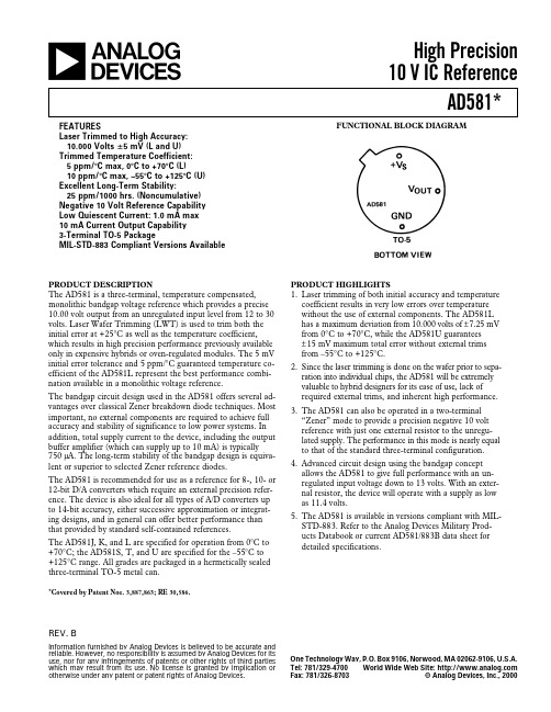
PRODUCT HIGHLIGHTS 1. Laser trimming of both initial accuracy and temperature
coefficient results in very low errors over temperature without the use of external components. The AD581L has a maximum deviation from 10.000 volts of ±7.25 mV from 0°C to +70°C, while the AD581U guarantees ± 15 mV maximum total error without external trims from –55°C to +125°C.
PACKAGE OPTION2 TO-5 (H-03B)
AD581J
Min
Typ
Max
AD581K
Min
Typ
Max
AD581L Min Typ Max
؎30
؎10
؎5
؎13.5 30
؎6.75 15
؎2.25 5
3.0 (0.002) 1.0 (0.005)
3.0 (0.002) 1.0 (0.005)
S-817A50中文资料

2
Seiko Instruments Inc.
元器件交易网
Rev.1.1
ULTRA COMPACT CMOS VOLTAGE REGULATOR S-817 Series
n Electrical Characteristics
1. S-817AXXANB Item
Table 4 Electrical Characteristics
元器件交易网
Contents
Features......................................................... 1 Applications ...................................................1 Block Diagram ...............................................1 Selection Guide..............................................2 Pin Assignment ..............................................2 Absolute Maximum Ratings............................2 Electrical Characteristics ................................3 Test Circuits...................................................4 Standard Circuit .............................................4 Technical Terms ............................................4 Operation .......................................................6 Selection of Output Capacitor (CL).................6 Applied circuit ................................................7 Design Considerations ...................................9 Typical Performance Curves ........................ 10 Transient Response Characteristics ............. 14 Dimensions, Taping ..................................... 19 Frequently Asked Questions........................22
S-816A50资料
元器件交易网ContentsFeatures (1)Block Diagram (1)Applications (1)Selection Guide (2)Pin Assignment (2)Absolute Maximum Ratings (3)Electrical Characteristics (3)Measurement Circuits (4)Operation (4)Selection of Associated External Components..6Standard Circuits (7)Precautions (7)Application Circuits (8)Outlines and Dimensions (11)Markings (11)Taping (11)Characteristics of Major Items (13)Tansient Response Characteristics (15)Frequently Asked Questions (17)Rev.3.0Seiko Instruments Inc. 1External Transistor Type Voltage Regulators S-816 SeriesThe S-816 Series consists of external transistor type positive voltage regulators,which have been developed using the CMOS process. These voltage regulators incorporate an overcurrent protection, and power-off function. A low drop-out type regulator with an output current ranging from several hundreds of mA to 1A can be configured with the PNP transistor driven by this IC.Despite the features of the S-816, which is low current consumption, the improvement in its transient response characteristics of the IC with a newly deviced phase compensation circuit made it possible to employ the products of the S-816Series even in applications where heavy input variation or load variation is experienced.The S-816 Series regulators serve as ideal power supply units for portable devices when coupled with the SOT-23-5 minipackage, providing numerous outstanding features, including low current consumption. Since this series can accommodate an input voltage of up to 16V, it is also suitable when operating via an AC adapter.nFeaturesn ApplicationsŸ Low current consumption In operation : 30 m A typ.40 m A max.When powered-off : 1 m A max.Ÿ Input voltage range : 16V max.Ÿ Output voltage accuracy : ± 2.0%Ÿ Output voltage range : Selectable between 2.5V and 6.0Vin steps of 0.1V.Ÿ With power-off function.Ÿ A built-in current source (10 uA) eliminates the need of a base-emitter resistance.Ÿ On-board power supplies of battery devices for portabletelephones, electronic notebooks, PDAs, and the like.Ÿ Fixed voltage power supplies for cameras, video equipment and portable communications equipment.Ÿ Power Supplies for CPUs.Ÿ Post-Regulators for Switching Regulators.Ÿ Main Regulators in Multiple-Power Supply Systems.Ÿ With overcurrent (base current) protection function.n Block Diagram-+EXTV OUTV SSON/OFFV INVrefCurrent SourceOvercurrentProtection CircuitPull-UpErrorAmplifierSink Driver-+Note: To ensure you power cutoff of the external transistor when the device is powered down, the EXT output is pulled up to VINby a pull-up resistance (approx. 0.5M W ) inside the IC.The diode inside the IC is a parasitic diode.Figure 1. Block DiagramExternal Transistor Type Voltage Regulators S-816 SeriesRev.3.02Seiko Instruments Inc.n Selection Guide1. Product NameS - 816A XX A MC - XXX - T2Tape Specifications Product Name Abbreviation Package Name Abbreviation Output Voltage x 102. Product List (As of May 28, 1998)Output Voltage (V)SOT-23-5Output Voltage (V)SOT-23-52.5V ±2.0%S-816A25AMC-BAA-T24.3V ±2.0%-2.6V ±2.0%- 4.4V ±2.0%-2.7V ±2.0%- 4.5V ±2.0%-2.8V ±2.0%- 4.6V ±2.0%-2.9V ±2.0%- 4.7V ±2.0%-3.0V ±2.0%S-816A30AMC-BAF-T24.8V ±2.0%-3.1V ±2.0%- 4.9V ±2.0%-3.2V ±2.0%-5.0V ±2.0%S-816A50AMC-BAZ-T23.3V ±2.0%S-816A33AMC-BAI-T25.1V ±2.0%-3.4V ±2.0%- 5.2V ±2.0%-3.5V ±2.0%- 5.3V ±2.0%-3.6V ±2.0%- 5.4V ±2.0%-3.7V ±2.0%S-816A37AMC-BAM-T25.5V ±2.0%-3.8V ±2.0%- 5.6V ±2.0%-3.9V ±2.0%- 5.7V ±2.0%-4.0V ±2.0%S-816A40AMC-BAP-T25.8V ±2.0%-4.1V ±2.0%- 5.9V ±2.0%-4.2V ±2.0%- 6.0V ±2.0%-Please contact the SII Sales Department regarding the availability of samples.nPin AssignmentSOT-23-5Top view 1 2 35 4Figure 2Terminal No.Terminal Name Function1EXT Output Terminal for Base-Current Control 2V SS GND Terminal3ON/OFF Power-Off Terminal ("H" active)4V IN IC Power Supply Terminal5V OUTOutput Voltage Monitoring TerminalExternal Transistor Type Voltage RegulatorsRev.3.0S-816 SeriesSeiko Instruments Inc.3nAbsolute Maximum RatingsNote: Although this IC incorporates an electrostatic protection circuit, the user is urged to avoid subjecting it to an extremely high static electricity or static voltage in excess of the performance of the said protection circuit.(Ta = 25°C, unless otherwise specified)ItemSymbol Ratings Unit V IN Terminal Voltage VIN V SS -0.3 to V SS +18V V OUT Terminal Voltage VOUT V SS -0.3 to V SS +18V ON/OFF Terminal Voltage ON/OFF V SS -0.3 to V SS +18V EXT Terminal Voltage VEXT V SS -0.3 to V IN +0.3V EXT Terminal Current IEXT 50mA Power DissipationPD 150mW Operating Temperature Range TOPR -40 to +85°C Storage Temperature RangeTSTG-40 to +125°CnElectrical Characteristics(Ta = 25°C, unless otherwise specified)ItemSymbol Conditions Min.Typ.Max.Unit Meas.CircuitInput Voltage VIN --16V 1Output VoltageVOUTV IN = VOUT + 1V,Iout = 50mA ON/OFF = "H"VOUT X 0.98VOUT VOUT X 1.02V 1Maximum Output Current (PNP Output) *1-1-A 1Drop-Out Voltage *1D VdropIout = 100mA -100-mV 1Load Regulation (PNP Output) *1D VOUTV IN = VOUT + 1V,1mA < Iout < 1A --60mV 1Line Regulation (PNP Output) *1D VOUTVOUT x D VIN Iout = 50mA,VOUT + 1V < V IN <16V -0.150.010.15%/V 1Output Voltage Temperature CoefficientD VOUT D Ta V IN = VOUT + 1V,Iout = 50mA ON/OFF = "H",Ta = -40 to 85 °C -±0.15-mV/°C 1Current Consumption during OperationISS V IN = VOUT + 1V,ON/OFF = ”H”-3040m A 1Current Consumption during Power-OffISTB V IN = 16V,ON/OFF = ”L”--1m A 1EXT Output Source Constant CurrentIsrc V IN = VOUT + 1V,ON/OFF = "H"EXT = VOUT,V OUT = VOUT x 0.95--10-m A 2EXT Output Pull-Up ResistanceRup V IN = 16V,ON/OFF = "L"0.250.50 1.00M W 2EXT Output Sink Current Isink V IN = VOUT + 1V,ON/OFF = "H"V OUT = VOUT x 0.95-10-mA 2Leakage Current during EXT Output OffIoff V IN = EXT = VOUT + 1V,V OUT = 0V ON/OFF = "L"--0.1m A 2EXT Output Sink Overcurrent Set ValueImax V IN = EXT = 7V,ON/OFF = "H"V OUT = VOUT x 0.95121620mA 2Power-Off Terminal Input Voltage VSH Check V IN = VOUT + 1V,V OUT = 0V,EXT = "L " 2.4--V 3VSL Check V IN = VOUT + 1V,V OUT = 0V,EXT = "H "--0.3V 3Power-Off Terminal Input CurrentISH ON/OFF = VOUT + 1V --0.1m A 2ISLON/OFF = 0V---0.1m A2*1 The characteristics vary with the associated external components.The characteristics given above are those obtained when the IC is combined with a Toshiba 2SA1213-Y for the PNP transistor and a 10 uF tantalum capacitor for the output capacitor (CL).External Transistor Type Voltage Regulators S-816 SeriesRev.3.04Seiko Instruments Inc.nMeasurement CircuitsV SSON/OFF1V INVV OUTEXT-+A A-+V SSON/OFF2V INV OUTEXTAAAAV SSON/OFF3V INV OUTEXTAAAVFigure 3nOperation1. Basic OperationFigure 4 shows a block diagram of the S-816 Series.The device compares the voltage which is obtained from dividing output voltage VOUT by feedback resistances RA and RB with reference voltage Vref through the error amplifier, output of which controls the sink driver. By regulating the base current of the external PNP transistor, the IC maintains a constant output voltage that is not susceptible to an input voltage variatio n or temperature variation.OUTINCL EXT V OUTV SSON/OFFV IN Vrefcurrent sourceOvercurrent protection circuitRBRARCError amplifierSink driver-+Figure 4External Transistor Type Voltage RegulatorsRev.3.0S-816 SeriesSeiko Instruments Inc.52. Internal Circuits2.1 Power-Off Terminal (ON/OFF Terminal)This terminal activates and deactivates the regulating operation.When the power-off terminal is set to "L", the VIN voltage appears through the EXT terminal, prodding the external PNP transistor to off. All the internal circuits stop working, and substantial savings in current consumption are achieved accordingly. In this condition, the EXT terminal is pulled up to VIN by a pull-up resistance (approx. 0.5M W ) inside the IC in order to ensure you power cut off of the external PNP transistor.The power-off terminal is configured as shown in Figure 5. Since neither pull-up or pull-down is performed internally,please avoid using the terminal in a floating state. Also, be sure to refrain from applying a voltage of 0.3V to 2.4V to this terminal lest the current consumption increase. When this power-off terminal is not used, leave it coupled to the V IN terminal.2.2 Overcurrent Protection CircuitThe overcurrent protection function of the S-816 Series monitors the EXT terminal sink current (base current of the external PNP transistor) with an overcurrent protection circuit incorporated in the IC, and limits that current (EXT terminal sink current).As the load current increases, the EXT terminal sink current (base current of the external PNP transistor) also grows larger to maintain the output voltage. The overcurrent protection circuit clamps and limits the EXT terminal sink current to the EXT output sink overcurrent set value (Imax) in order to prevent it from increasing beyond that value. The load current at which the overcurrent protection function works is represented by the following equation: Iout_max = Imax ´ hfeIn this case, hfe is the DC amplification factor of the external PNP transistor.Iout_max represents the maximum output current of this regulator. If it is attempted to obtain a higher load current, the output voltage will fall.Note that within the overcurrent protection function of this IC, the external PNP transistor may not be able to be protected from collector overcurrents produced by an EXT-GND short-circuiting or other phenomenon occurring outside the IC. To protect the external PNP transistor from such collector overcurrents, it will be necessary to choose a transistor with a larger power dissipation than Iout_max ´ VIN, or to add an external overcurrent protection circuit. With regard to this external overcurrent protection circuit, please refer to "Application Circuits and Overcurrent Protection Circuit" on page 8.2.3 Phase Compensation CircuitThe S-816 Series performs phase compensation with a phase compensation circuit, incorporated in the IC, and the ESR (Equivalent Series Resistance) of an output capacitor, to secure stable operation even in the presence of output load variation. A uniquely devised phase compensation circuit has resulted in improved transient response characteristics of the IC, while preserving the same feature of low current consumption. This feature allows the IC to be used in applications where the input variation or load variation is heavy.Because the S-816 Series is designed to perform the phase compensation, utilizing the ESR of an output capacitor,such output capacitor (CL) should always be placed between V OUT and V SS . Since each capacitor to be employed has an optimum range of their own characteristics, be sure to choose components for the IC with your all attention. For details,refer to "Selection of Associated External Components."Power-Off Terminal Internal Circuit EXT Terminal VoltageV OUT Terminal Voltage"H"Activated VIN-VBE Set value "L"DeactivatedVINHi-zFigure 5ON/OFFV INV SSExternal Transistor Type Voltage Regulators S-816 SeriesRev.3.06Seiko Instruments Inc.nSelection of Associated External Components1. External PNP transistorSelect an external transistor according to the conditions of input voltage, output voltage, and output current. A low-saturation voltage PNP transistor with 'hfe' ranging from 100 to 300 will be suitable for this IC.The parameters for selection of the external PNP transistor include the maximum collector-base voltage, the maximum collector-emitter voltage, the DC amplification factor (hfe), the maximum collector current and the collector dissipation. The maximum collector-base voltage and the maximum collector-emitter voltage are determined by the input voltage range in each specific application to be employed. You may select a transistor with an input voltage at least several volts higher than the expected maximum input voltage.The DC amplification factor (hfe) affects the maximum output current that can be supplied to the load.With an internal overcurrent protection circuit of this IC, the base current is clamped, and will not exceed the overcurrent set value (Imax). Select a transistor which is capable of delivering the required maximum output current to the intended application,with hfe and maximum collector current. (See the paragraph of Overcurrent Protection Circuit on page 5)Likewise, select a transistor, based on the maximum output current and the difference between the input and output voltages,with due attention to the collector dissipation.2. Output Capacitor (CL)The S-816 Series performs phase compensation by an internal phase compensation circuit of IC, and the ESR (Equivalent Series Resistance) of an output capacitor for to secure stable operation even in the presence of output load variation. Therefore,always place a capacitor (CL) of 4.7uF or more between V OUT and V ss .For stable operation of the S-816 Series, it is essential to employ a capacitor with an ESR having optimum range. Whether an ESR is larger or smaller than that optimum range (approximately 0.1W to 5W ), this could produce an unstable output, and cause a possibility of oscillations. For this reason, a tantalum electrolytic capacitor is recommended.When a ceramic capacitor or an OS capacitor having a low ESR is selected, it will be necessary to connect an additional resistance that serves for the ESR in series with the output capacitor, as illustrated in Figure 6. The resistance value that needs to be added will be from 0.1W to 5W , but this value may vary depends on the service conditions, and should be defined through careful evaluation in advance. In general, our recommendation is 0.3W or so.An aluminum electrolytic capacitor tends to produce oscillations as its ESR increases at a low temperature. Beware of this case. When this type of capacitor is employed, make thorough evaluation of it, including its temperature characteristics.OUTINR @ 0.3WCLS-816 SeriesEXT V OUTV SSON/OFFV IN Figure 6External Transistor Type Voltage RegulatorsRev.3.0S-816 SeriesSeiko Instruments Inc.7nStandard Circuit-+EXT V OUTV SSON/OFFV IN VrefCurrent sourceOvercurrent protection circuitPull-upError amplifierSink driver-+Figure 7nPrecautionslThe overcurrent protection function of this IC detects and limits the sink current at the EXT terminal inside the IC.Therefore, it does not work on collector overcurrents which are caused by an EXT-GND short-circuiting or other phenomenon outside the IC. To protect the external PNP transistor from collector overcurrents perfectly, it is necessary to provide another external overcurrent protection circuit.lThis IC performs phase compensation by using an internal phase compensator circuit and the ESR of an output capacitor.Therefore, always place a capacitor of 4.7uF or more between V OUT and Vss. A tantalum type capacitor is recommended for this purpose. Moreover, to secure stable operation of the S-816 Series, it will be necessary to employ a capacitor having an ESR (Equivalent Series Resistance) covered in a certain optimum range (0.1W to 5W ). Whether an ESR is larger or smaller than that optimum range, this could result in an unstable output, and cause a possibility of oscillations.Select a capacitor through careful evaluation made according to the actual service conditions.lMake sure that the power dissipation inside the IC due to the EXT output sink current (especially at a high temperature)will not surpass the power dissipation of the package.300200100 0050100150Power DissipationP D(mW)Ambient Temperature Ta(°C)Figure 8. Power Dissipation of SOT-23-5 Package (When Not Mounted)lSeiko Instruments Inc. shall not be responsible for any patent infringement by products including the S-816 Series in connection with the method of using the S-816 in such products, the product specifications or the country of destination thereof.External Transistor Type Voltage Regulators S-816 SeriesRev.3.08Seiko Instruments Inc.n Application Circuits1. Overcurrent protection circuitFigure 9 shows a sample of overcurrent protection implemented with an external circuit connected.The internal overcurrent protection function of the S-816 Series is designed to detect the sink current (base current of the PNP transistor) at the EXT terminal, therefore it may not be able to protect the external PNP transistor from collector overcurrents caused by an EXT-GND short-circuiting or other phenomenon occurring outside the IC.This sample circuit activates the regulator intermittently against collector overcurrents, thereby suppressing the heat generation of the external PNP transistor.The duty of the on-time and off-time of the intermittent operation can be regulated through an external component.S-816 SeriesEXT V OUTV SSON/OFFV INOUT+-Tr.1C10.22uFTr.2VINR1R3100k W2k W0.5W2k W2k WCL 10uF10uFCIN 2SA1213Y Rs +-R2R4C20.22uFFigure 9S-816A30AMC (VIN:4V)t(2msec/div)Load Current (0.5A/div)0A1A 2V ON/OFF (1V/div)0VS-816A30AMC (VIN:4V)t(100µsec/div)(0.5A/div)0A1A 2V ON/OFF (1V/div)0VLoad Current Figure 10. Output Current Waveforms during Intermittent Operation Prompted by Load Short-CircuitingThe detection of the overcurrent is done by the sense resistance (Rs) and the PNP transistor (Tr.1).When Tr.1 comes on, triggered by a voltage drop of Rs, the NPN transistor (Tr.2) also comes on, according to the time constants of the capacitor (C2) and resistance (R2). This causes the power-off terminal to turn to the 'L' level, and the regulating operation to stop, and interrupting the current to the load.When the load current is cut off, the voltage drop of Rs stops. This makes Tr.1 off again, and also makes the NPN transistor (Tr.2) off.In this condition, the power-off terminal returns to the 'H' level, according to the time constants of the capacitor (C1) and resistance (R1). This delay time in which power-off terminal returns to the 'H' level from the 'L' level is the time in which the load current remains cut off.If an overcurrent flows again after the power-off terminal has assumed the 'H' level following the delay time and the regulating operation has been restarted, the circuit will again suspend the regulating operation and resume the intermittent operation. This intermittent operation will be continued till the overcurrentt is eliminated, and once theovercurrent disappears, the normal operation will be restored.External Transistor Type Voltage RegulatorsRev.3.0S-816 SeriesSeiko Instruments Inc.9The overcurrent detection value (Iout_max) is represented by the following equation: Iout_max = |VBE1| / RsIn this case, Rs denotes the resistance value of the sense resistance, and VBE1 denotes the base-emitter saturation voltage of Tr.1.For the PNP transistor (Tr.1) and the NPN transistor (Tr.2), try to select those of small-signal type that offer a sufficient withstand voltage against the input voltage (VIN).The on-time (Ton) and the off-time (Toff) of the intermittent operation are broadly expressed by the following equations: Ton = -1 ´ C2 ´ R2 ´ Ln( 1 - ( VBE2 ´ ( 1 + R2 / R3 ) ) / ( VIN - VBE1 ) ) Toff = -1 ´ C1 ´ R1 ´ Ln( 1 - VSH / VIN )In this case, VBE2 denotes the base-emitter saturation voltage of Tr.2, VIN denotes the input voltage, and VSH denotes the inversion voltage (L ®H) of the power-off terminal.Set the on-time value that does not cause the overcurrent protection to be activated by a rush current to the load capacitor.Then, compute the ratio between the on-time and the off-time from the maximum input voltage of the appropriate application and the power dissipation of the external PNP transistor, and decide the off-time with reference to the on-time established earlier.Take the equation above as a rough guide, because the actual on-time (Ton) and off-time (Toff) should be defined and checked using the utilizing components.2. External adjustment of output voltageThe S-816 Series allows you to adjust the output voltage or to set its value over the output voltage range (6V) of the products of this series, when external resistances RA, RB and capacitor CC are added, as illustrated in Figure 11. Moreover, a temperature gradient can be obtained by inserting a thermistor or other element in series with external resistances RA and RB.ErroramplifierR2R1CC RBRAVrefEXTV OUTV SSON/OFFV IN OUT+-CL +-VINCINFigure 11The S-816 Series has an internal impedance resulting from R1 and R2 between the V OUT and the Vss terminal, as shown in Figure 11. Therefore, the influence of the internal resistances (R1, R2) of the IC has to be taken into consideration in defining the output voltage (OUT).The output voltage (OUT) is expressed by the following equation:OUT = VOUT + VOUT ´ RA ¸ ( RB // RI ) (Note: // denotes a combined resistance in parallel.)In this case, VOUT is the output voltage value of the S-816 Series, RA and RB is the resistance values of the external resistances, and RI is the resistance value (R1+R2) of the internal resistances in the IC.The accuracy of the output voltage (OUT) is determined by the absolute accuracy of external connecting resistances RA and RB, the output voltage accuracy (VOUT ±2.0%) of the S-816 Series, and deviations in the absolute value of the internal resistance (RI) in the IC.The maximum value (OUTmax) and the minimum value (OUTmin) of the output voltage (OUT), including deviations, are expressed by the following equations:OUTmax = VOUT ´ 1.02 + VOUT ´ 1.02 ´ RAmax ¸ ( RBmin // RImin ) OUTmin = VOUT ´ 0.98 + VOUT ´ 0.98 ´ RAmin ¸ ( RBmax // RImax )External Transistor Type Voltage RegulatorsS-816 Series Rev.3.0Where RAmax, RAmin, RBmax and RBmin denote the maximum and minimum of the absolute accuracy of external resistances RA and RB, and RImax and RImin denote the maximum and minimum deviations of the absolute value of the internal resistance (RI) in the IC, respectively.The deviations in the absolute value of internal resistance (RI) in the IC vary with the output voltage set value of the S-816 Series, and are broadly classified as follows:· Output voltage(VOUT) 2.5V to 2.7V Þ 3.29M W to 21.78M W· Output voltage(VOUT) 2.8V to 3.1V Þ 3.29M W to 20.06M W· Output voltage(VOUT) 3.2V to 3.7V Þ 2.23M W to 18.33M W· Output voltage(VOUT) 3.8V to 5.1V Þ 2.23M W to 16.61M W· Output voltage(VOUT) 5.2V to 6.0V Þ 2.25M W to 14.18M WIf a value of RI given by the equation shown below is taken in calculating the output voltage (OUT), a median voltage deviation of the output voltage (OUT) will be obtained.RI = 2 ¸ ( 1 ¸ (Maximum value of internal resistance of IC) + 1 ¸ (Minimum value of internal resistance of IC) )The closer the output voltage (OUT) and the output voltage set value (VOUT) of the IC are brought to each other, the more the accuracy of the output voltage (OUT) remains immune to deviations in the absolute accuracy of external resistances (RA and RB) and the absolute value of the internal resistance (RI) of the IC.In particular, to suppress the influence of deviations in the internal resistance (RI), the resistance values of external resistances (RA, RB) need to be limited to a much smaller value than that of the internal resistance (RI). However, since reactive current flows through the external resistances (RA, RB), there is a tradeoff between the accuracy of the output voltage (OUT) and the reactive current. This should be taken into consideration, according to the requirements of the intended application.Note that when larger value (more than 1M W) is taken for the external resistances (RA, RB), IC is vulnerable to external noise.Check the influence of this value well with the actual application.Furthermore, add a capacitor CC in parallel to the external resistance RA in order to avoid output oscillations and other types of instability. (See Figure 11.)Make sure that the capacitance value of CC is larger than the value given by the following equation:CC[F] ³ 1 ¸ ( 2 ´p´ RA[W] ´ 6000 )·SII is equipped with a tool that allows you to calculate the necessary resistance values of the external resistances (RA, RB) automatically. SII will be pleased to assist its customers with their design work. Should such assistance be desired, please inquire at:SII Components Sales Dept. Telephone: 043-211-1192 (Direct) Fax: 043-211-8032External Transistor Type Voltage RegulatorsRev.3.0S-816 Seriesn Outlines and Dimensions0.95±0.10.4±0.10 m in. 1.1±0.1 1.3 max.1.62.9(3.1max.)2.8+0.2- 0.31.9±0.20.160.45+0.1- 0.060.95±0.1Unit: mmFigure 12n Marking•‚ƒ………• ~ ƒ Product No. (Abbreviation)… ~ … Lot No.… : Alphabet… : A dot marked on either sideFigure 13nTaping1. Tape specifications3.23±0.13° or less3.2±0.10.27±0.05 1.4±0.13° or less4.0±0.1f 1.0f 1.5+0.1- 02.0±0.054.0±0.1 (Cumulative 10 pitches: 40.0±0.2)1.75±0.13.5±0.058.0±0.2+0.2- 0Unit: mmFeed directionType T2Figure 14External Transistor Type Voltage Regulators S-816 SeriesRev.3.02. Reel specificationsOne reel holds 3,000 ICs.Unit: mm12.5Max.2.0±0.210.5±0.4(60°)(60°)f 180+0-3Size of outermostcircumferencef 13.0±0.2(1.5)f 60+1-09.0±0.3Size of reel winding core11.4±1.0Size of reel winding coreFigure 15External Transistor Type Voltage RegulatorsRev.3.0S-816 SeriesnCharacteristics of Major Items (All data represent typical values)1. Input Voltage (VIN) - Output Voltage (VOUT) Characteristics2. Output Current (IOUT) - Output Voltage (VOUT) Characteristics3. Temperature (Ta) - Output Voltage (VOUT) CharacteristicsVIN-VOUTS-816A30AMC (Ta=25°C)2.802.852.90 2.953.003.053.102.82.93.03.13.23.3 3.43.53.63.73.8VIN(V)VOUT(V)VIN-VOUTS-816A50AMC (Ta=25°C)4.804.854.904.955.005.055.104.84.95.05.15.25.3 5.45.55.65.75.8VIN(V)VOUT(V)Iout=1m AIout=100m A Iout=500m A Iout=1AIout=1m AIout=100m A Iout=500m A Iout=1ATa-VOUTS-816A30AMC (VIN=4V,Iout=50m A)2.902.922.942.962.983.003.023.043.063.083.10-50-25255075100Ta(°C)VOUT(V)Ta-VOUTS-816A50AMC (VIN=6V,Iout=50m A)4.904.924.944.964.985.005.025.045.065.085.10-50-25255075100Ta(°C)VOUT(V)IOUT-VOUTS-816A30AMC (VIN=4V)2.902.922.942.962.983.003.023.043.063.083.101101001000IOUT(m A)VOUT(V)IOUT-VOUTS-816A50AMC (VIN=6V)4.904.924.944.964.985.005.025.045.065.085.101101001000IOUT(m A)VOUT(V)Ta=85°C Ta=25°C Ta=-40°CTa=25°C Ta=85°CTa=-40°C VIN-VOUTS-816A30AMC (Iout=50m A)2.902.922.942.962.983.003.023.043.063.083.10246810121416VIN(V)VOUT(V)VIN-VOUTS-816A50AMC (Iout=50m A)4.904.924.944.964.985.005.025.045.065.085.10246810121416VIN(V)VOUT(V)Ta=-40°CTa=85°CTa=25°C Ta=85°CTa=-40°CTa=25°C。
BK5811Datasheetv1.1
BK5811Low Power High Performance 5GHz GFSK TransceiverFeatures⏹ Support 5G two frequency bands :Pin AssignmentsVDDPALNAIN POUTN VSS CDVDD VDD VSS IREF VSS POUTP VDD LNAIPBK5811 Table of Contents1General Description (3)2Abbreviations (4)3Pin Information (5)4State Control (6)4.1State Control Diagram (6)4.2Power Down Mode (7)4.3Standby-I Mode (7)4.4Standby-II Mode (7)4.5TX Mode (7)4.6RX Mode (8)5Packet Processing (8)5.1Packet Format (8)5.1.1Preamble (9)5.1.2Address (9)5.1.3Packet Control (9)5.1.4Payload (10)5.1.5CRC (10)5.2Packet Handling (10)6Data and Control Interface (11)6.1TX/RX FIFO (11)6.2Interrupt (11)6.3SPI Interface (12)6.3.1SPI Command (12)6.3.2SPI Timing (13)7Register Map (15)7.1Register Bank 0 (15)7.2Register Bank 1 (21)8Electrical Specifications (22)9Typical Application Schematic (23)10Package Information (24)11Order information (25)12Contact Information (25)1 General DescriptionBK5811 is a GFSK transceiver operating in the frequency band at 5135MHz-5262MHz or 5725MHz-5852MHz..Burst mode transmission and up to 2Mbps air data rate make them suitable for applicationsfrequency is set by the RF_CH register in register bank 0 according to the following formula: F0= 5135(or 5725) + RF_CH (MHz). The resolution of the RF channel frequency is 1MHz.be with the data by inFigure 1 BK5811 Chip Block Diagram2AbbreviationsACK AcknowledgementARC Auto Retransmission CountARD Auto Retransmission DelayCD Carrier DetectionCE Chip EnableCRC Cyclic Redundancy CheckCSN Chip Select NotDPL Dynamic Payload LengthFIFO First-In-First-OutGFSK Gaussian Frequency Shift Keying GHz GigahertzLNA Low Noise AmplifierIRQ Interrupt RequestISM Industrial-Scientific-Medical LSB Least Significant BitMAX_RT Maximum RetransmitMbps Megabit per secondMCU Microcontroller UnitMHz MegahertzMISO Master In Slave OutMOSI Master Out Slave InMSB Most Significant BitPA Power AmplifierPID Packet Identity BitsPLD PayloadPRX Primary RXPTX Primary TXPWD_DWN Power DownPWD_UP Power UpRF_CH Radio Frequency ChannelRSSI Received Signal Strength Indicator RX ReceiveRX_DR Receive Data ReadySCK SPI ClockSPI Serial Peripheral InterfaceTDD Time Division DuplexTX TransmitTX_DS Transmit Data SentXTAL Crystal3 Pin InformationVSS CDVDD VDD VSS IREF VDD4 State Control4.1 State Control Diagram⏹ Pin signal: VDD, CE⏹ SPI register: PWR_UP, PRIM_RX,EN_AA, NO_ACK, ARC, ARD⏹BK5811 has built-in state machines that control the state transition between different modes. bydevice enters standby-I mode. Standby-I mode is used to minimize average current consumption while maintaining short start-up time. In this mode, part of the crystal oscillator is active. This is also the mode which the BK5811 returns to from TX or RX mode when CE is set low.areTXwillPTX device (PRIM_RX=0)The TX mode is an active mode where the PTX device transmits a packet. To enter this mode from power down mode, the PTX device must have the PWR_UP bit set high, PRIM_RX bit set low, a payload in the TX FIFO, and a high pulse on the CE for more than 10µs.The PTX device stays in TX mode until it finishes transmitting the current packet. If CE = 0 it returns to standby-I mode. If CE = 1, the next action is determined by the status of the TX FIFO. If the TX FIFO is not empty the PTX device remains in TX mode, transmitting the next packet. If the TX FIFO is empty the PTX device goes into standby-II mode. It is important to never stay in TX mode for morehigh, PRIM_RX bit set high and the CE pin set high. Or PRX device can enter this mode from TX mode after transmitting an acknowledge packet when EN_AA=1 and NO_ACK=0 in received packet.In this mode the receiver demodulates the signals from the RF channel, constantly presenting the demodulated data to the packet a sFigure 5 Packet Format5.1.1PreambleThe preamble is a bit sequence used to detect 0 and 1 levels in the receiver. The preamble is one byte long and is either 01010101 or 10101010. If the first bit in the address is 1 the preamble is automatically set to 10101010 and if the first bit is 0 the preamble is automatically set to 01010101. This is done to ensure there are enough transitions in the preamble to stabilize the receiver.5.1.2AddressThis is the address for the receiver. An address ensures that the packet is detected by the target receiver. The address field can be configured to be 3, 4, or 5 bytes long by the AW register. The PRX device can open up to six data pipes to support up to six PTX devices with unique addresses. All six PTX device addresses are searched simultaneously. In PRX side, the data pipes are enabled with the bits in the EN_RXADDR register. By default only data pipe 0 and 1 are enabled.Each data pipe address is configured in the RX_ADDR_PX registers.Each pipe can have up to 5 bytes configurable address. Data pipe 0 has a unique 5 byte address. Data pipes 1-5 share the 4 most significant address bytes. The LSB byte must be unique for all 6 pipes.To ensure that the ACK packet from the PRX is transmitted to the correct PTX, the PRX takes the data pipe address where it received the packet and uses it as the TX address when transmitting the ACK packet.On the PRX the RX_ADDR_Pn, defined as the pipe address, must be unique. On the PTX the TX_ADDR must be the same as the RX_ADDR_P0 on the PTX, and as the pipe address for the designated pipe on the PRX. No other data pipe can receive data until a complete packet is received by a data pipe that has detected its address. When multiple PTX devices are transmitting to a PRX, the ARD can be used to skew the auto retransmission so that they only block each other once.5.1.3Packet ControlWhen Dynamic Payload Length function is enabled, the packet control field contains a 6 bit payload length field, a 2 bit PID (Packet Identity) field and, a 1 bit NO_ACK flag.⏹Payload lengthThe payload length field is only used if the Dynamic Payload Length function is enabled.⏹PIDThe 2 bit PID field is used to detect whether the received packet is new or retransmitted. PID prevents the PRX device from presenting the same payload more than once to the MCU. The PID field is incremented at the TX side for each new packet received through the SPI. The PID and CRC fields are used by the PRX device to determine whether a packet is old or new. When several data packets are lost on the link, the PID fields may become equal to the last received PID. If a packet has the same PID as the previous packet, BK5811 compares the CRC sums from both packets. If the CRC sums are also equal, the last received packet is considered a copy of the previously received packet and discarded.⏹NO_ACKThe NO_ACK flag is only used when the auto acknowledgement feature is used. Setting the flag high, tells the receiver that the packet is not to be auto acknowledged.The PTX can set the NO_ACK flag bit in the Packet Control Field with the command: W_TX_PAYLOAD_NOACK. However, the function must first be enabled in the FEATURE register by setting theEN_DYN_ACK bit. When you use this option, the PTX goes directly to standby-I mode after transmitting the packet and the PRX does not transmit an ACK packet when it receives the packet.5.1.4PayloadThe payload is the user defined content of the packet. It can be 0 to 32 bytes wide, and it is transmitted on-air as it is uploaded (unmodified) to the device.The BK5811 provides two alternatives for handling payload lengths, static and dynamic payload length. The static payload length of each of six data pipes can be individually set. The default alternative is static payload length. With static payload length all packets between a transmitter and a receiver have the same length. Static payload length is set by the RX_PW_Px registers. The payload length on the transmitter side is set by the number of bytes clocked into the TX_FIFO and must equal the value in the RX_PW_Px register on the receiver side. Each pipe has its own payload length.Dynamic Payload Length (DPL) is an alternative to static payload length. DPL enables the transmitter to send packets with variable payload length to the receiver. This means for a system with different payload lengths it is not necessary to scale the packet length to the longest payload.With DPL feature the BK5811 can decode the payload length of the received packet automatically instead of using the RX_PW_Px registers. The MCU can read the length of the received payload by using the command: R_RX_PL_WID.In order to enable DPL the EN_DPL bit in the FEATURE register must be set. In RX mode the DYNPD register has to be set. A PTX that transmits to a PRX with DPL enabled must have the DPL_P0 bit in DYNPD set. 5.1.5CRCThe CRC is the error detection mechanism in the packet. The number of bytes in the CRC is set by the CRCO bit in the CONFIG register. It may be either 1 or 2 bytes and is calculated over the address, Packet Control Field, and Payload.The polynomial for 1 byte CRC is X8 + X2 + X + 1. Initial value is 0xFF.The polynomial for 2 byte CRC is X16 + X12 + X5 + 1. Initial value is 0xFFFF.No packet is accepted by receiver side if the CRC fails.5.2Packet HandlingBK5811 uses burst mode for payload transmission and receive.The transmitter fetches payload from TX FIFO, automatically assembles it into packet and transmits the packet in a very short burst period with 1Mbps or 2Mbps air data rate. After transmission, if the PTX packet has the NO_ACK flag set, BK5811 sets TX_DS and gives an active low interrupt IRQ to MCU. If the PTX is ACK packet, the PTX needs receive ACK from the PRX and then asserts the TX_DS IRQ.The receiver automatically validates and disassembles received packet, if there is a valid packet within the new payload, it will write the payload into RX FIFO, set RX_DR and give an active low interrupt IRQ to MCU. When auto acknowledge is enabled (EN_AA=1), the PTX device will automatically wait for acknowledge packet after transmission, and re-transmit original packet with the delay of ARD until an acknowledge packet is received or the number of re-transmission exceeds a threshold ARC. If the later one happens, BK5811 will set MAX_RT and give an active low interruptIRQ to MCU. Two packet loss counters (ARC_CNT and PLOS_CNT) are incremented each time a packet is lost. The ARC_CNT counts the number of retransmissions for the current transaction. The PLOS_CNT counts the total number of retransmissions since the last channel change. ARC_CNT is reset by initiating a new transaction. PLOS_CNT is reset by writing to the RF_CH register. It is possible to use the information in the OBSERVE_TX register to make an overall assessment of the channel quality.The PTX device will retransmit if its RX FIFO is full but received ACK frame has payload. As an alternative for PTX device to auto retransmit it is possible to manually set the BK5811 to retransmit a packet a number of times. This is done by the REUSE_TX_PL command.When auto acknowledge is enabled, the PRX device will automatically check the NO_ACK field in received packet, and if NO_ACK=0, it will automatically send an acknowledge packet to PTX device. If EN_ACK_PAY is set, and the acknowledge packet can also include pending payload in TX FIFO.6Data and Control Interface 6.1TX/RX FIFOThe data FIFOs are used to store payload that is to be transmitted (TX FIFO) or payload that is received and ready to be clocked out (RX FIFO). The FIFO is accessible in both PTX mode and PRX mode.There are three levels 32 bytes FIFO for both TX and RX, supporting both acknowledge mode or no acknowledge mode with up to six pipes.⏹TX three levels, 32 byte FIFO⏹RX three levels, 32 byte FIFOBoth FIFOs have a controller and are accessible through the SPI by using dedicated SPI commands. A TX FIFO in PRX can store payload for ACK packets to three different PTX devices. If the TX FIFO contains more than one payload to a pipe, payloads are handled using the first in first out principle. The TX FIFO in a PRX is blocked if all pending payloads are addressed to pipes where the link to the PTX is lost. In this case, the MCU can flush the TX FIFO by using the FLUSH_TX command.The RX FIFO in PRX may contain payload from up to three different PTX devices..A TX FIFO in PTX can have up to three payloads stored.The TX FIFO can be written to by three commands, W_TX_PAYLOAD and W_TX_PAYLOAD_NO_ACK in PTX mode and W_ACK_PAYLOAD in PRX mode. All three commands give access to the TX_PLD register.The RX FIFO can be read by the command R_RX_PAYLOAD in both PTX and PRX mode. This command gives access to the RX_PLD register.The payload in TX FIFO in a PTX is NOT removed if the MAX_RT IRQ is asserted.In the FIFO_STATUS register it is possible to read if the TX and RX FIFO are full or empty. The TX_REUSE bit is also available in the FIFO_STATUS register. TX_REUSE is set by the SPI command REUSE_TX_PL, and is reset by the SPI command: W_TX_PAYLOAD or FLUSH TX.6.2InterruptIn BK5811 there is an active low interrupt (IRQ) pin, which is activated when TX_DS IRQ, RX_DR IRQ or MAX_RT IRQ are set high by the state machine in the STATUS register. The IRQ pin resets when MCU writes '1' to the IRQ source bit in the STATUS register. The IRQ mask in the CONFIGregister is used to select the IRQ sources that are allowed to assert the IRQ pin. By setting one of the MASK bits high, the corresponding IRQ source is disabled. By default all IRQ sources are enabled.The 3 bit pipe information in the STATUS register is updated during the IRQ pin high to low transition. If the STATUS register is readto low transition on CSN.In parallel to the SPI command word applied on the MOSI pin, the STATUS register is shifted serially out on the MISO pin.The serial shifting SPI commands is in the following format:Figure 6 SPI timingCn: SPI command bitSn: STATUS register bitDn: Data Bit (LSB byte to MSB byte, MSB bit in each byte first)Note: The SPI timing is for bank 0 and register 9 to 14 at bank 1. For register 0 to 8 at bank 1, the byte order is inversed that the MSB byte is R/W before LSB byte.7Register MapThere are two register banks, which can be toggled by SPI command “ACTIVATE” followed with 0x53 byte, and bank status can be read from Bank0_REG7 [7].7.1Register Bank 07.2Register Bank 18Electrical Specifications9Typical Application SchematicPlease refer to the document “BK5811 Hardware Reference Design”.10Package InformationBK5811 uses the QFN24 4x4 package, with matt tin plating.Table 7 QFN4*4 24 Pin Package dimensions11 Order InformationTable 8 BK5811 order information Remark:MOQ: Minimum Order Quantity12Contact InformationBeken Corporation Technical Support CenterShanghai officeSuite 3A,1278 Keyuan Road, Zhangjiang High-Tech Park, Pudong New District, Shanghai, P.R. ChinaPhone: 86-21-51086811,60871276Fax: 86-21-60871277Postal Code: 201203Email: info@Website: Shenzhen officeRoom 718,Shenzhen High-Tech Industrial Estate,Nanshan, Shenzhen, P.R. ChinaPhone: 86-755-2655 1063Postal Code: 518057。
IST8310 datasheet
IST83103D Magnetometer DatasheetTable of Contents1 GENERAL DESCRIPTION (4)2 BLOCK DIAGRAM, PACKAGE DIMENSION AND APPLICATION CIRCUIT (5)2.1 Block diagram (5)2.2 Package Dimensions and Pin Description (5)2.3 Application Circuit (7)3 OPERATIONAL MODES AND FUNCTIONAL DESCRIPTIONS (8)3.1 Operation modes (8)3.1.1 Stand-By Mode (8)3.1.2 Single Measurement Mode (8)3.1.3 Self-Test Mode (8)3.2 Interrupt Function (9)3.3 DRDY Function (9)3.4 IST8310 Read Process (9)4 ELECTRICAL SPECIFICATIONS (10)4.1 Extreme Rating (10)4.2 Recommended Operating Conditions (10)4.3 Electrical Specifications (10)4.4 Magnetic Sensor Specifications (11)4.5 Power On Reset (POR) Specifications (12)5 TECHNOLOGY OVERVIEW (13)5.1 AMR Technology (13)5.2 High Reliability Planarized Design (13)5.3 Ultra-low Hysteresis Design (13)5.4 Magnetic Setting Mechanism (13)6 DIGITAL INTERFACE AND REGISTERS (14)6.1 I2C Interface (14)6.2 I2C Read Operation (14)6.3 I2C Write Operation (15)6.4 Registers (15)7 ORDERING INFORMATION (21)1 General DescriptioniSentek IST8310 is a 3-axis digital magnetometer with 3.0x3.0x1.0mm3, 16-pin LGA package. It is an integrated chip with 3-axis magnetic sensors, digital control logic, built-in temperature compensation circuit and self-test function. IST8310 provides an I2C digital output with fast mode up to 400kHz. The high output data rate, ultra-low hysteresis, excellent temperature drift and low noise performance feathers make it a perfect candidate for high accuracy applications.Features●Single chip 3-axis magnetic sensor● 3.0x3.0x1.0mm3, 16-pin LGA package●I2C slave, Fast Mode up to 400kHz●14 bits data output●Wide dynamic range of ±1600uT (x, y-axis) and ±2500uT (z-axis)●High output data rate of maximum 200Hz●Ultra-low hysteresis (<0.1%FS)●Ultra-low sensitivity temperature drift (±0.016 %/ o K)●Ultra-low offset temperature drift (0.024uT/ o K)●Wide operating temperature range●High precision temperature compensation●Built-in self-test function●Software and algorithm support available (For tilt compensation, cross-axis compensation andnoise suppression)ApplicationsQuadcopter/Drone ApplicationsAugmented Reality ApplicationsVirtual Reality ApplicationsLocation Based ServicesNavigation ApplicationsIndustrial ApplicationsMagnetometryIOT devicesHeadingGaming2 Block Diagram, Package Dimension and Application Circuit2.1 Block diagramFigure 1. Block Diagram2.2 Package Dimensions and Pin DescriptionUnit: mmTolerance: ±0.1mmSDADRDY SCLAVDDVSSRSTNC1VPPCAD0CAD1DVDDIST8310 LGA Top View (Looking Through)Unit: mmTolerance: ±0.1mm*please refer to Figure 2.IST8310 LGA Side ViewIST8310 3D Top View2.3 Application CircuitFigure 2. Application Circuit4.7uFRSTNDRDY3 Operational Modes and Functional Descriptions3.1 Operation modesIST8310 has following operation modes:(1) Stand-By Mode(2) Single Measurement Mode(3) Self-Test Mode3.1.1 Stand-By ModeThe initial mode (after power on) of IST8310 is Stand-By Mode. In Stand-By Mode, all internal circuits are off (except oscillator and regulator). All registers can be accessed in Stand-By Mode. Data stored in Read/Write registers remains as last state. Registers can be reset by soft reset or hard reset (through RSTN pin).As initial setting, please set Pulse Duration Control Register, PDCTNL(0x42) = 11000000b (C0H) for performance optimization. For low noise performance, please set Average Control Register, AVGCNTL(0x41) = 00100100b (24H) for more internal average times. The minimum waiting time between two measurements under low noise performance setup is 6ms (166Hz).3.1.2 Single Measurement ModeIn Single Measurement Mode, the measured data is stored in data registers then IST8310 transits to Stand-By Mode automatically. On transition to Stand-By Mode, Control register 1(CNTL1[3:0]) turns to “0000”. At the same time, DRDY bit in STA T1 register turns to “1”. This is called “data ready”. When any of the measurement data registers or STA T2 register is read, DRDY bit turns to “0”. For the next measurement, user needs to set Control register 1(CNTL1[3:0]) to “0001” again. The minimum waiting time between two measurements in default setup is 5ms (200Hz).Please noted in IST8310, ultra-low noise performance is obtained through soft-averaging in driver. Please contact iSentek for technical details.3.1.3 Self-Test ModeSelf-Test mode is used to check if the 3-axis outputs read in Single Measurement Mode are correct. It is activated by setting Self-Test Register (0x0C) to 40h; then all 3-axis outputs will change their polarity. User can check the 3-axis output values before and after activating Self-Test Mode; if the absolute values are the same, then the IC is working correctly. It can be turned off by setting Self-Test Register (0x0C) to 00h.3.2 Interrupt FunctionInterrupt function is used when there is a huge external magnetic field in the surrounding. When the absolute sum of measured 3-axis output value exceeds 1600 uT, the INT flag is activated. The INT flag can be found in STA T2 register.3.3 DRDY FunctionDRDY function is used when the output data is updated. The DRDY pin is used to monitor the data ready output. DRDY is changed to low after reading data from the output register.3.4 IST8310 Read Process(1) Read STAT1 register:‐Polling STAT1 register bit 0‐DRDY: shows if the data is ready or not0: no data ready1: data ready‐DOR: shows if any data has been skipped before the current data0: no skipped data1: data skipped.(2) Read Measurement Data:Read Register 0x03h~0x08h for X, Y and Z axis data. When data reading starts, DRDY bit and DOR bit turn t o “0”.4 Electrical Specifications4.1 Absolute Maximum Ratings2. Machine Model (MM)4.2 Recommended Operating Conditions4.3 Electrical Specifications(Operating conditions: TA=+25℃; A VDD=2.8V; DVDD=1.8V; 0.1µF ceramic capacitors tied closely to AVDD/DVDD and GND respectively.)4.4 Magnetic Sensor Specifications(Operating conditions: Ta=+25℃; A VDD=2.8V; DVDD=1.8V; 4.7µF ceramic capacitors tied closely to C1 and GND respectively. )4.5 Power On Reset (POR) SpecificationsWhen POR circuit detects the rise of A VDD voltage, it resets all internal circuits and initializes all registers. After reset, IST8310 transits to Stand-By mode.PSTO: Power Supply Turn Off voltage PSOI: Power Supply Turn Off Interval POR: Power On ResetPORPSTO: max=0.1volt PSOI: min=10ms POR: max:50ms5 Technology Overview5.1 AMR TechnologyIST8310, an iSentek patented magnetometer is designed based on Anisotropy Magneto-Resistance (AMR) technology. The output is generated from the resistance change of the AMR resistors while external magnetic field changes. The sensitivity is about 50 to 200 times larger than traditional Hall element. The high sensitivity allows higher output data rate (ODR), lower noise and lower power consumption.5.2 High Reliability Planarized Structure DesignIST8310 consists of three full Whetstone Bridge of AMR resistors. The three bridges detecting magnetic component in three directions orthogonal to each other are located on one chip, wire-bonded to a control ASIC. This planarized structure design enables outstanding stability to thermal shock, making our device highly reliable, immune from thermal reflow-induced failure. While other known AMR magnetometers placing z-axis sensor vertical to the substrate using 90-degree flip-chip packaging suffers from reliability issues5.3 Ultra-low Hysteresis DesigniSentek has developed a specialized high permeability (μ) material for magnetic field detection. This high-μ material has ultra-low residual magnetization below 0.1 %FS in the field range as large as +/- 500 G. The ultra-low hysteresis design prevents the magnetometer from dynamic offset after encountering a strong external magnetic field impact; that is, the angular accuracy restores automatically without calibration after the removal of interference field. This feature fulfills the requirements for applications when real time calibration is not available. No calibration is required in general conditions.5.4 Magnetic Setting MechanismAMR sensing resistors consist of Permalloy thin film and metallization. Permalloy is soft magnetic, irreversible magnetic rotation may occur after the strength of external magnetic field exceeds half of the anisotropy field of the sensing resistor, resulting in angular error induced by offset. To solve this issue, a magnetic setting mechanism is introduced in IST8310. A magnetic field is generated within IST8310 to align the magnetization of AMR sensing resistors before every measurement. This auto-zeroing mechanism ensures the stability of angular accuracy of IST8310 during whole operation.6 Digital Interface and Registers6.1 I 2C InterfaceThe interface of IST8310 follows the standard I 2C definition guidelines with some additional protocol definitions. IST8310 supports standard speed (100kHz) and fast speed (400kHz). Pull-up resistors of 4.7kohm for both SDA and SCL lines should be used.Figure 3. I 2C Operation6.1.1 Slave AddressMSB LSB(CAD1), the corresponding 7-bit and 8-bit defined I 2C slave addresses are listed below:6.2 I2C Read OperationFigure 4. I C Single Byte Read OperationACK: Acknowledge, NA: Not Acknowledge, SA: START Condition, SP: Repeat Start Condition, ST: STOP Condition ■: Slave to MasterFigure 5. I C Multiple Byte Read OperationACK: Acknowledge, NA: Not Acknowledge, SA: START Condition, SP: Repeat Start Condition, ST: STOP Condition ■: Slave to Master6.3 I 2C Write OperationFigure 6. I C Single Byte Write OperationACK: Acknowledge, NA: Not Acknowledge, SA: START Condition, SP: Repeat Start Condition, ST: STOP Condition ■: Slave to MasterFigure 7. I C Multiple Byte Write OperationACK: Acknowledge, NA: Not Acknowledge, SA: START Condition, SP: Repeat Start Condition, ST: STOP Condition ■: Slave to Master6.4 Registers6.4.1 Customer Defined Registers6.4.2 Who Am I RegisterThis Register provides device ID information6.4.3 Status Register 1This Register provides status information of IST83106.4.4 Output Data RegistersThe Output Registers (from 0x03h~0x08h) contain X, Y and Z axis measurement data. Measurement data are stored in 2’s complement format.6.4.5 Status Register 2In this register, there is an INT flag for customer use.6.4.6 Control Setting Register 1This Register controls and adjusts the main parameters.6.4.7 Control Setting Register 2This Register controls and adjusts the main parameters.6.4.8 Self-Test Register6.4.9 Temperature Sensor Output RegistersThe Output Data Registers use 2’s complement format.6.4.10 Average Control RegisterThis register controls the times of average done in the circuit to lower the noise. Higher average times leads to lower noise.6.4.11 Pulse Duration Control RegisterThis register controls the pulse duration for set/reset function of AMR sensors.IST8310IST8310 Datasheet, Version 1.2217 Ordering InformationFor more information on iSentek’s Magnetic Sensors, please contact us by phone at +86-132-6706-8686 (China), +86-755-3337-0168 (China) or +886-2-2698-3306 ext:110 (Taiwan); via e-mail: sales@ or visit us online at .The application circuits herein constitute typical usage and interface of iSentek’s product. iSentek does not warranty or assume liability of customer-designed circuits derived from this description or depiction.iSentek reserves the right to make changes to improve reliability, function or design. iSentek does not assume any liability arising out of the application or use of any product or circuit described herein; neither does it convey any license under its patent rights nor the rights of others.US Patent 9,297,863, Taiwanese Patents I437249, I420128 and I463160 apply to our magnetic sensor technology described.。
5821中文资料
BiMOS II 8-BIT SERIAL-INPUT,LATCHED DRIVERSAlways order by complete part number, e.g., UCN5821A .Data Sheet 26185.12E5821 AND 5822A merged combination of bipolar and MOS technology gives these devices an interface flexibility beyond the reach of standard logic buffers and power driver arrays. The UCN5821A,UCN5821LW, UCN5822A, and UCN5822LW each have an eight-bit CMOS shift register and CMOS control circuitry, eight CMOS data latches, and eight bipolar current-sinking Darlington output drivers. The UCN5821A/LW and UCN5822A/LW are identical except for rated output voltage.BiMOS II devices have much higher data-input rates than the original BiMOS circuits. With a 5 V logic supply, they will typically operate at better than 5 MHz. With a 12 V supply,significantly higher speeds are obtained. The CMOS inputs are compatible with standard CMOS and NMOS logic levels. TTL circuits may require the use of appropriate pull-up resistors. By using the serial data output, the drivers can be cascaded for interface applications requiring additional drive lines.The UCN5821/22A are furnished in a standard 16-pin plastic DIP; the UCN5821/22LW are in a 16-lead wide-body SOIC for surface-mount applications. The UCN5821A is also available for operation from -40°C to +85°C. To order, change the prefix from ‘UCN’ to ‘UCQ’.FEATURESI To 3.3 MHz Data Input Rate I CMOS, NMOS, TTL Compatible I Internal Pull-Down ResistorsI Low-Power CMOS Logic & Latches I High-Voltage Current-Sink Outputs I Automotive Capable5821 AND 58228-BIT SERIAL-INPUT,LATCHED DRIVERS115 Northeast Cutoff, Box 15036Worcester, Massachusetts 01615-0036 (508) 853-5000Copyright © 1985, 2000, Allegro MicroSystems, Inc.5821 AND 5822 8-BIT SERIAL-INPUT, LATCHED DRIVERS LimitsCharacteristic Symbol Test Conditions Min.Max.Units Output Leakage I CEX UCN5821A/LW, V OUT = 50 V—50µACurrent UCN5822A/LW, VOUT= 80 V—50µAUCN5821A/LW, V OUT = 50 V, T A = +70°C—100µAUCN5822A/LW, V OUT = 80 V, T A = +70°C—100µA Collector-Emitter V CE(SAT)I OUT = 100 mA— 1.1VSaturation Voltage IOUT= 200 mA— 1.3VI OUT = 350 mA, V DD = 7.0 V— 1.6V Input Voltage V IN(0)—0.8VV IN(1)V DD = 12 V10.5—VV DD = 5.0 V 3.5—V Input Resistance r IN V DD = 12 V50—kΩV DD = 5.0 V50—kΩSupply Current I DD(ON)One Driver ON, V DD = 12 V— 4.5mAOne Driver ON, V DD = 10 V— 3.9mAOne Driver ON, V DD = 5.0 V— 2.4mAI DD(OFF)V DD = 5.0 V, All Drivers OFF, All Inputs = 0 V— 1.6mAV DD = 12 V, All Drivers OFF, All Inputs = 0 V— 2.9mA ELECTRICAL CHARACTERISTICS at T A = +25°C, V DD = 5 V, (unless otherwise specified).5821 AND 58228-BIT SERIAL-INPUT,LATCHED DRIVERS115 Northeast Cutoff, Box 15036Worcester, Massachusetts 01615-0036 (508) 853-5000TIMING CONDITIONS(V DD = 5.0 V, T A = +25°C, Logic Levels are V DD and Ground)A.Minimum Data Active Time Before Clock Pulse(Data Set-Up Time).......................................................................75 ns B.Minimum Data Active Time After Clock Pulse(Data Hold Time)...........................................................................75 ns C.Minimum Data Pulse Width..............................................................150 ns D.Minimum Clock Pulse Width ............................................................150 ns E.Minimum Time Between Clock Activation and Strobe.......................30 ns F.Minimum Strobe Pulse Width...........................................................100 nsG.Typical Time Between Strobe Activation andOutput Transition ..........................................................................1.0 µsL = Low Logic Level H = High Logic Level X = Irrelevant P = Present State R = Previous StateDwg. No. A-12,627Serial Data present at the input is transferred to the shift register on the logic “0” to logic “1” transition of the CLOCK input pulse. On succeeding CLOCK pulses, the registers shift data information towards the SERIAL DATA OUTPUT. The SERIAL DATA must appear at the input prior to the rising edge of the CLOCK input waveform.Information present at any register is transferred to its respective latch when the STROBE is high (serial-to-parallel con-version). The latches will continue to accept new data as long as the STROBE is held high. Applications where the latches are bypassed (STROBE tied high)will require that the ENABLE input be high during serial data entry.When the ENABLE input is high, all of the output buffers are disabled (OFF)without affecting the information stored in the latches or shift register. With the ENABLE input low, the outputs are controlled by the state of the latches.CLOCKDATA INSTROBEENABLE OUT5821 AND 58228-BIT SERIAL-INPUT,LATCHED DRIVERSNOTES: 1.Lead thickness is measured at seating plane or below.2.Lead spacing tolerance is non-cumulative.3.Exact body and lead configuration at vendor’s option within limits shown.Dwg. MA-001-16A inDwg. MA-001-16A mmUCN5821A and UCN5822ADimensions in Inches (controlling dimensions)Dimensions in Millimeters(for reference only)5821 AND 58228-BIT SERIAL-INPUT,LATCHED DRIVERS115 Northeast Cutoff, Box 15036Worcester, Massachusetts 01615-0036 (508) 853-5000NOTES: 1.Lead spacing tolerance is non-cumulative.2.Exact body and lead configuration at vendor’s option within limits shown.UCN5821LW and UCN5822LWDimensions in Inches (for reference only)(controlling dimensions)5821 AND 5822 8-BIT SERIAL-INPUT, LATCHED DRIVERSThe products described here are manufactured under one or more U.S. patents or U.S. patents pending.Allegro MicroSystems, Inc. reserves the right to make, from time to time, such departures from the detail specifications as may be required to permit improvements in the performance, reliability, or manufacturability of its products. Before placing an order, the user is cautioned to verify that the information being relied upon is current.Allegro products are not authorized for use as critical components in life-support devices or systems without express written approval.The information included herein is believed to be accurate and reliable. However, Allegro MicroSystems, Inc. assumes no responsi-bility for its use; nor for any infringement of patents or other rights of third parties which may result from its use.5821 AND 58228-BIT SERIAL-INPUT,LATCHED DRIVERS115 Northeast Cutoff, Box 15036Worcester, Massachusetts 01615-0036 (508) 853-5000POWERINTERFACE DRIVERSFunctionOutput Ratings*Part Number †SERIAL-INPUT LATCHED DRIVERS8-Bit (saturated drivers)-120 mA 50 V‡58958-Bit350 mA 50 V58218-Bit350 mA 80 V58228-Bit350 mA 50 V‡58418-Bit 350 mA 80 V‡58428-Bit (constant-current LED d river)75 mA 17 V62758-Bit (DMOS d rivers)250 mA 50 V65958-Bit (DMOS drivers)350 mA 50 V‡6A5958-Bit (DMOS drivers)100 mA 50 V6B59510-Bit (active pull-d owns)-25 mA 60 V5810-F an d 6809/1012-Bit (active pull-downs)-25 mA 60 V5811 an d 681116-Bit (constant-current LED driver)75 mA 17 V627620-Bit (active pull-d owns)-25 mA 60 V5812-F an d681232-Bit (active pull-d owns)-25 mA 60 V5818-F an d 681832-Bit100 mA 30 V583332-Bit (saturate d d rivers)100 mA 40 V5832PARALLEL-INPUT LATCHED DRIVERS4-Bit350 mA 50 V‡58008-Bit -25 mA 60 V58158-Bit350 mA 50 V‡58018-Bit (DMOS d rivers)100 mA 50 V6B2738-Bit (DMOS d rivers)250 mA 50 V6273SPECIAL-PURPOSE DEVICESUnipolar Stepper Motor Translator/Driver 1.25 A 50 V‡5804A ressable 8-Bit Deco der/DMOS Driver 250 mA 50 V6259Addressable 8-Bit Decoder/DMOS Driver 350 mA 50 V‡6A259A ressable 8-Bit Deco d er/DMOS Driver 100 mA 50 V6B259A ressable 28-Line Deco d er/Driver 450 mA30 V6817*Current is maximum specified test condition, voltage is maximum rating. See specification for sustaining voltage limits.Negative current is defined as coming out of (sourcing) the output.†Complete part number includes additional characters to indicate operating temperature range and package style.‡Internal transient-suppression diodes included for inductive-load protection.。
- 1、下载文档前请自行甄别文档内容的完整性,平台不提供额外的编辑、内容补充、找答案等附加服务。
- 2、"仅部分预览"的文档,不可在线预览部分如存在完整性等问题,可反馈申请退款(可完整预览的文档不适用该条件!)。
- 3、如文档侵犯您的权益,请联系客服反馈,我们会尽快为您处理(人工客服工作时间:9:00-18:30)。
η (% )
GS5810
50 40 30 20 10 0 0 200 400 600 800 1000 1200 1400 Io(mA)
VIN=6.0V VIN=5.0V VIN=4.2V VIN=3.6V VIN=2.7V VIN=2.5V
FB
V
FB
= 0.65V 0.04
A A A
Reference Voltage Line Regulation Regulated Output Voltage
V = 2.5V to 5.5V,
IN
0.40 1.236 1.545 1.854 0.40
GS5810-1.2, -40° C≤T GS5810-1.5, -40° C≤T GS5810-1.8, -40° C≤T Output Voltage Line Regulation Output Voltage Load Regulation Peak Inductor Current Oscillator Frequency R of P-CH MOSFET
unit V µA µA V V V nA %/V V V V % %
=90% 0.5880
V =0V, V =4.2V T = +25° C
A A
350 0.1 0.6000 0.6000 0.6000 0.5865 0.5820
T = 0° C≤T
A
A A
≤ 85° C ≤ 85° C
T = -40° C≤T
深圳市中广芯源科技有限公司
GS5810
1.5MHz, 1.0A Synchronous Step-Down Converter
Description
T he GS 5810 is a high efficiency mo no lithic synchronous buck regulator using a constant frequency, current mode architecture. The device is available in an adjustable version and fixed output voltages, such as 1.2V, 1.5V, 1.8V, etc. Supply current with no load is 350uA and drops to <1uA in shutdown. The 2.5V to 6.5V input voltage range makes the GS5810 ideally suited for single Li-Ion, two to four AA battery-powered applications. 100% duty cycle provides low dropout operation, extending battery life in portable systems. PWM pulse skipping mode operation provides very low output ripple voltage for noise sensitive applications. Switching frequency is internally set at 1.5MHz, allowing the use of small surface mount inductors and capacitors. The internal synchronous switch increases efficiency and eliminates the need for an external Schottky diode. Low output voltages are easily supported with the 0.6V feedback reference voltage. The GS5810 is available in a small SOT89-5 package.
FB OUT
OUT
=90%
1.00 1.2
1.20 1.5 0.40 0.35
1.45 1.8 0.45 0.40 ± 1 0.6
A MHz Ω Ω µA V µA
I I
SW SW
= 300mA = -300mA = 0V, V
SW
R
of N-CH MOSFET
SW Leakage RUN Threshold Low RUN Threshold High RUN Leakage Current characterization.
IN FB IN
GS5810
Operating Temperature Range...........-40° C to +85° C Junction Temperature ............................+125° C Storage Temperature Range............-65° C to +150° C Lead Temperature (Soldering, 10s)................+300° C
PDAs MP3 / MP4 /PMP Player Digital Still and Video Cameras Portable Instruments MID or UMPC
Features
High Efficiency: Up to 96% 1.5MHz Constant Switching Frequency 1.0A Output Current at Vin=3.6V & Vout=1.8V Integrated Main switch and synchronous rectifier. No Schottky Diode Required 2.5V to 6.5V Input Voltage Range Output Voltage as Low as 0.6V 100% Duty Cycle in Dropout Quiescent Current: 350µA(input < 4.2V) Slope Compensated Current Mode Control for Excellent Line and Load Transient Response Short Circuit Protection Thermal Fault Protection <1uA Shutdown Current
TEL:0755-27668758/29469758
web:
深圳市中广芯源科技有限公司
Electrical Characteristics
(V =V
IN RUN
GS5810
= 3.6V, TA = 25° C, unless otherwise noted.) Conditions V =0.5V or V
Thermal Resistance
Package SOT89-5
:
Ө 45° C/W
JC
Ө
160° C/W
JA
Note 1: Absolute Maximum Ratings are those values beyond which the life of a device may be impaired. Note 2: TJ is calculated from the ambient temperature TA and power dissipation PD according to the following formula: GS5810: TJ = TA + (PD)x(160° C/W) . Pay attention on the actual power dissipation in the application Note 3: Thermal Resistance is specified with approximately 1 square of 1 oz copper. Note 4: XY = Manufacturing Date Code
Figure 1. Basic Application Circuit with GS5810 adjustable version
Figure 2. Typical Efficiency Curve
TEL:0755-27668758/29469758
web:
(Note 2)
Package/Order Information Adjustable Output Version:
Part Number GS5810ES5-ADJ
SOT89-5 Top Mark Temp Range (Note 4) -40° C to +85° C E1XY
(Note 3)
TEL:0755-27668758/29469758
web:
深圳市中广芯源科技有限公司
Typical Performance Characteristics (Test Figure 1 above unless otherwise specified)
DS(ON) DS(ON)
≤ 85° C ≤ 85° C ≤ 85° C
1.164 1.455 1.746
1.200 1.500 1.800 0.04 0.5
V = 2.5V to 5.5V
IN
V =3V, V =0.5V or V
IN FB
Duty Cycle <35% V =0.6V or V =100%
深圳市中广芯源科技有限公司