4路高速脉冲输出的应用例程说明
拉雷尔电子有限公司 QLS 四通道输出 4-20ma 流量循环重传设备说明说明书

Operating Temperature Storage Temperature Relative Humidity 0 mA, 1-5V, 0-5V, 0-10V (jumper selectable) 50 Ω for 4-20 mA, 412 kΩ for 1-5V, 464 kΩ for 0-5V, 935 kΩ for 0-10V 24 Vdc, 30 mA max
LAUREL ELECTRONICS INC., 3183-G Airway Ave., Costa Mesa, CA 92626, USA • Tel 714-434-6131 •
1
Specifications
Signal Input
Signal Type Input Resistance Transmitter Excitation
5. Each loop only drives a single load, thus avoiding voltage compliance problems.
6. ±10% of zero and span adjustment are provided for each output loop to allow for independent loop calibration.
35 mm DIN Rail per EN50 022 22.5 x 103 x 128 mm (0.9" x 4.1" x 5.0") W x H x D 140 g (5 oz) Detachable plug-in screw-clamp connectors 28-12 AWG, 2.5 sq. mm max
Signal Outputs
基于寄存器操作的STM32高级定时器TIM1的四路PWM输出程序讲解
基于寄存器操作的STM32高级定时器TIM1的四路PWM输出程序讲解经过一天的努力,终于把stm32tim1的四路pwm输出搞了出来,为了使大家快速的用起tim1,打算写这篇文档与大家分享。
Stm32tim1功能丰富。
由于PWM输出和TIM2之间只有很小的差别,我在网上找到了一些网友的程序,发现大多数程序都是基于库文件编写的,所以我无法深入了解TIM1的PWM 输出。
我认为一个想要充分利用芯片的合格程序员应该直接对寄存器进行操作,并充分了解计时器的操作过程,你可以对电影的结构有一定的了解。
高级控制定时器(tim1和tim8)由一个16位的自动装载计数器组成,它由一个可编程的预分频器驱动。
它适合多种用途,包含测量输入信号的脉冲宽度(输入捕获),或者产生输出波形(输出比较、pwm、嵌入死区时间的互补pwm等)。
使用定时器预分频器和rcc时钟控制预分频器,可以实现脉冲宽度和波形周期从几个微秒到几个毫秒的调节。
高级控制定时器(TIM1和tim8)和通用定时器(timx)是完全独立的,它们不共享任何资源。
请读者仔细阅读一下信息:脉冲宽度调制模式可由timx生成。
ARR寄存器确定频率,该频率由timx确定。
ccrx寄存器确定占空比信号。
在timx中,ccmrx寄存器中的ocxm位被写入“110”(PWM模式1)或“111”(PWM模式2),这可以独立设置每个OCX输出通道以生成一个PWM。
必须设置timx。
ccmrx寄存器的ocxpe位启用相应的预加载寄存器。
最后,应设置timx。
CR1寄存器的ARPE位(在递增计数或中心对称模式下)使预加载的寄存器能够自动重新加载。
只有在发生更新事件时,预加载寄存器才能传输到卷影寄存器,因此必须在计数器开始计算EGR寄存器中的μg位之前设置timx,以初始化所有寄存器。
可通过软件在timx中检测OCX的极性。
CCER寄存器中的ccxp位已设置,可设置为高级有效或低级有效。
【三菱案例】高速脉冲输出——多位移动案例

【三菱案例】高速脉冲输出——多位移动案例高速脉冲输出——多位移动案例程序截图内容分析开机初始化程序使用开机脉冲信号,传送不同的数值,且进行浮点数运算求出一个脉冲所走的长度。
1.使用【MOV】指令传送K20(周长)、K400(一圈的脉冲数)到D2、D4;2.使用【FLT】整数转浮点数指令,把周长和脉冲转换成浮点数(小数);3.使用【DEDIV】浮点数除法运算,用周长(D6)除以一圈的脉冲数(D8),得出一个脉冲所走的长度(D10);4.使用【MOV】传送指令,把变址寄存器V0清零。
不同点位长度设置使用【M3】辅助继电器控制参数写入,主要是写入不同长度,有多少个长度就写入几条指令,本截图7个长度,所以有七条指令。
注意:此程序是配合触摸屏使用,D50到D62的数值由触摸屏输入。
1.使用【FLT】整数转浮点数指令,把通过触摸屏输入的数值(D50到D62)转换成浮点数存放在(D100到D112中);2.使用【DEDIV】浮点数除法指令,把设定的长度除以一个脉冲走的长度,得出设定长度所需的脉冲数;3.使用【INT】浮点数转整数指令,把求得的每段长度所需的脉冲数转换成整数,以供发脉冲指令使用;发脉冲指令执行部分使用【M0】辅助继电器【SET】置位【M1】,把启动信号保持住,在使用【M1】常开触点驱动【PLSY】高速脉冲输出指令,把【D200V0】的脉冲数以800HZ的频率通过【Y0】口发送出去,其中【D200V0】使用了变址,这样就只需要编辑一条发脉冲指令。
1.【M8029】脉冲结束标志位,脉冲发送完了之后,接通一个扫描周期。
即:【D200V0】找寻到的地址内的脉冲数发送完成后接通一瞬间。
2.使用【M8029】复位【M1】停止驱动发脉冲指令,再置位【M2】作为停止信号;3.使用【M2】的常开触点,接通一个定时器,做停止时间,停止1秒;同时使用【ADDP】加法指令,改变变址寄存器【V0】的数值(此段为可以看为加2计数),且复位【M2】;再使用定时器【T0】的上升沿重启激活【PLSY】发脉冲指令;4.使用触点比较指令,当【D200V0】的数值为零时,就停止所有启动信号,使其不能输出;已走长度部分1.使用【M8000】开机一直接通辅助继电器,驱动【DMOV】32位传送指令,把【D8140】Y0发出的脉冲总数传送给【D0】;2.使用【FLT】整数转浮点数指令,把总脉冲数转为浮点数存入【D20】;3.使用【DEMUL】浮点数乘法运算,把【D20】总输出脉冲数乘上【D10】一个脉冲所走的长度,结果存放在【D22】中,即:D22等于当前总长度。
X4脉冲款说明

特殊部分介绍:内部CPU都为FX1N,编程选择CPU都为FX1N,下载设置波特率位9.6K.产品分为MR继电器和MT晶体管,都可以支持4路脉冲,继电器输出频率不足,如需要驱动步进电机或者伺服电机请选用MT. 四路高速脉冲输出,单路单独输出最高频率可达100K. 内置高速计数器,支持单相单计数输入、单相双计数输入、双相双计数输入。
(包括高速脉冲输入在内的同时使用总频率不可超过200K Hz.高速计数频率:单相10K,双相5k.)内置实时钟(万年历,可选),485通信口(编程口模式,可选)2路模拟量输出(可选),2路模拟量输入(可选).另外内置2路电位器模拟量.关键字设置为“12345678”后,程序将读取出来无效,直到下一次程序被重新写入。
彻底解决程序不被读取。
(按钮STOP下写入)关于软元件范围请参考FX1N文档.作为Yn输出定位指令的当前值数据寄存器使用。
用PLSV,DRVI,DRVA指令时,对应旋转方向增减当前值。
另外由于PLSY,PLSR指令也使用相同当前值寄存器,因此当执行这些指令时,当前值的数值为脉冲输出值的累加值。
关于脉冲口的接线:驱动方式为驱动器正极接入PLC输出24V正极,驱动器的负极每一个口串联一个2-3K,4分之一瓦电阻接到Y口.关于扩展功能接口:RS485功能D8120:1编程通信:编程通信可实现PLC程序的下载以及监视,也可用于与文本显示器或者人机界面的通信。
通信规格:9600bps波特率,偶校验,7位数据长度,1位停止位设置方法:设置D8120为0(默认值)即是编程通信功能。
2无协议通信:无协议通信通过RS指令来实现数据的交互。
设置方法:确保D8120的b10,b11,b12位号全部为0,b14为0,其余字节请参考上面表格。
3计算机链接通信:通过此通信功能可实现计算机对PLC的集中管理以及数据采集。
设置方法:确保D8120的b10,b11,b12位号全部为0,b14为1,其余字节请参考上面表格。
GC-4674 4 通道模拟量输出模块(0V~+10V)用户手册说明书

GC-46744-channel analog output module(0V~+10V)User manualDocument version:V3.01(2020/12/21)Vhandy Technology GC-4674user manualContents1.Function introduction (3)1.1Function overview (3)1.2Performance characteristics (3)1.3Typical application (3)2.Equipment installation and use (3)2.1Module fixing (4)2.2Wiring method (4)2.3System status indicator (6)2.4Use in combination with PLC400/510series (6)2.5Combination with GCAN-IO-8000series equipment (7)3.Technical specifications (8)4.Disclaimer (9)5.Module selection table (10)Sales and service (12)1.Function introduction1.1Function overviewGC-4674(4-channel analog output module,0V~+10V)can be used to output signals in the range of0V~+10V.This terminal module can provide electrical isolation signals with a resolution of12bits for the processing layer.The GC-4674module has 2two-wire output terminals,which are especially suitable for installation in a control cabinet to save space.The GC-4674module has a common ground potential terminal, and the power contacts are connected together.The reference ground of the output terminal is the0V power contact.1.2Performance characteristics●The number of output points is4;●The signal voltage is0V~+10V;●Power supply via GC-bus;●The measurement error is less than±0.1%(full scale);●The measurement resolution is12bits;●The conversion time is about4ms;●The electrical isolation is1500Vrms(GC-bus/signal voltage);●GC-bus current consumption is150mA;●The bit width output in the process image is4x2bytes;●Configuration without address settings,through the bus coupler or controller configuration;●Applicable to all GCAN-PLC-400series and GCAN-8000series bus terminal modules;●Working temperature range:-40℃~+85℃;●Size:length100mm*width69mm*height12mm.1.3Typical application●The standard analog signal can be output according to the instruction;●It can be used to adjust the opening of valves,gates and other control equipment;●Connect to the bus coupler or controller to realize the transmission of analog signals.2.Equipment installation and useThis chapter will explain in detail the installation method,wiring method,meaning of the indicator light and the meaning of the interface of the GC-4674module.2.1Module fixingThe installation method of GC-4674module is shown in Figure2.1.You need to use a flat-blade screwdriver to assist in installation.Figure2.1GC-4674module installationFirst,you need to install the fieldbus coupler on the rail,and then attach the GC-4674 module to the right side of the fieldbus coupler or other modules to add this component.Please insert the GC-4674module inward along the slot as shown in Figure2.1until the lock catches.The GC-4674module is powered by GC-bus,no additional power supply is required. You only need to connect the power supply to the bus coupler and connect the GC-4674to the module composed of the bus coupler to realize the power supply of the GC-4674.2.2Wiring methodAs shown in Figure2.2,first insert a flat-blade screwdriver into the square hole and hold the screw in the square hole.Then insert the cable into the circular hole.After plugging it in,pull out the screwdriver and the cable can be firmly locked in the circular hole.Figure2.2GC-4674module installationFigure2.3GC-4674module wiring terminal blockThe wiring terminal block of GC-4674module is shown in Figure2.3.GC-4674 contains2groups of output points,and can connect to2groups of analog signals at most.The serial numbers corresponding to each terminal and their meanings are shown in Table2.1.2.3System status indicatorThe GC-4674module has2running indicators to indicate the running status of the device.The specific indication function of the indicator light is shown in Table2.2.When the output signal of the GC-4674module is activated,the running indicator will2.4Use in combination with PLC400/510seriesGCAN-PLC-400/510supports programming in five languages.The following uses ST language as an example to introduce how to use GCAN-PLC-400to program and write the status of the analog output of the GC-4674module.When GC-4674module performs ST programming definition,it is necessary to define the variable type,output signal position,start character,separator,etc.For example: "AO AT%Q0.0:INT;",where"0.0"represents the start address of the first channel, each channel occupies2bytes,0V~+10V corresponds to0~4095,so the second channel’s The starting address is Q2.0.When the user uses more than one GC-4674 module,the second GC-4674needs to be defined from"Q8.0",because each4674has 4channels;"%"(percent sign)is the direct variable start symbol:":"(semicolon)is a variable or type e the symbol variable AO to write the signed integer from the%Q0.0address.AT stands for the address of variable access and theadditional attributes of the variable(Note:Input only affects input,output only affects output,and output and input do not affect each other.That is,if there is and only an input module in front of the output module,then no matter how many input modules there are in front,the address of the first output module is still Q0.0.)2.5Combination with GCAN-IO-8000series equipmentThe status of the analog output is represented by two bytes.For example: GCAN-IO-8000module node number is1,if you want the input state of channel1of the first GC-4674module to be+5V,and the input state of other channels are all0V, you need to set the GCAN-IO-8000module Write CAN data frame ID is0x201,data length(DLC)is8,frame data is0xFF,0x07,0x00,0x00,0x00,0x00,0x00,0x00 data.3.Technical specifications4.DisclaimerThank you for purchasing GCAN's GCAN series of hardware and software products. GCAN is a registered trademark of Shenyang Vhandy Technology Co.,Ltd.This product and manual are copyrighted by Vhandy Technology.Without permission,it is not allowed to reproduce in any form.Before using,please read this statement carefully.Once used,it is deemed to be an endorsement and acceptance of the entire content of this statement.Please strictly abide by the manual,product description and related laws,regulations,policies and guidelines to install and use the product.In the process of using the product,the user promises to be responsible for his actions and all consequences arising therefrom.Vhandy Technology will not be liable for any losses caused by improper use,installation,or modification by users.The final interpretation right of the disclaimer belongs to Vhandy TechnologyVhandy Technology GC-4674user manual 5.Module selection tableGCAN-PLC-400series products consist of a programmable main control module, several GC series IO modules and a terminal resistance module.GC series IO modules currently include five categories:digital input,digital output, analog input,analog output,and communication extension.The specific selectionGC-3844/3854/3864K type/S type/T typethermocoupleThermocouple4-channelAnalog output GC-4602Voltage output,16bits-5V~+5V2-channel GC-4622Voltage output,16bits-10V~+10V2-channel GC-4642Current output,16bits0-20mA2-channel GC-4652Current output,16bits4-20mA2-channel GC-4662Voltage output,16bits0~5V2-channel GC-4672Voltage output,16bits0~10V2-channel GC-4674Voltage output,12bits0~10V4-channelSpecial module GC-6101RS232/RS485extension--GC-6201GPRS extension--GC-62214G extension--GC-6501WiFi extension--Table5.1Selection tableSales and serviceShenyang Vhandy Technology Co.,Ltd.Address:Room401,D11Block,SISP.,Hunnan District,Shenyang,Liaoning,China E-mail:****************Tel/Whatsapp:+86136****1762Skype:live:sygckjWeChat:gckj777Website:。
Morningstar 四通道逻辑控制器应用指南说明书
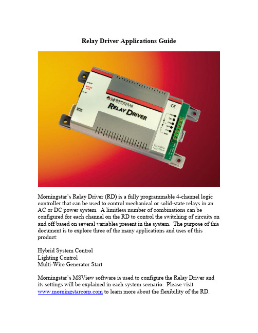
Relay Driver Applications GuideMorningstar’s Relay Driver (RD) is a fully programmable 4-channel logic controller that can be used to control mechanical or solid-state relays in an AC or DC power system. A limitless number of combinations can be configured for each channel on the RD to control the switching of circuits on and off based on several variables present in the system. The purpose of this document is to explore three of the many applications and uses of this product:Hybrid System ControlLighting ControlMulti-Wire Generator StartMorningstar’s MSView software is used to configure the Relay Driver and its settings will be explained in each system scenario. Please visit to learn more about the flexibility of the RD.Hybrid System Control –Alarm Signals and Generator ControlIn this application, the Relay Driver is used to send voltage alarms to a communications device provided by the user at the site. It also will monitor battery voltage and start a generator whenever there is insufficient solar charging from the PV array.The first channel controls the generator. In this particular application, the generator has its own internal warm-up and starting controls. Therefore only a single circuit is needed for the sequence to begin. The generator control mode can be used, but only one wire (the “run” signal) needs to be set up since the generator’s own controls take care of the rest of the start sequence. Two relay channel outputs (channels 2 and 3) are used to signal high and low voltage alarms on the battery bank. This alerts the user of the system (through a spare input on the communications link of their equipment) thatthe battery is higher or lower than the normal operating range due to a fault of some type.Finally, channel number 4 signals if there is a fault with the TriStar controller itself. This may indicate a higher level hardware failure regarding the TriStar’s operation that could not be detected with simple voltage readings. Each of the final channel setups are shown in Fig. 1Fig. 1 Hybrid ConfigurationThe first 3 channels are just threshold settings allowing the relay to be switched on when a certain voltage is met and turned off when that level returns to the normal range. Fig. 2 shows this set up for the gen start (channel 1). The gen start mode allows a delay time to be set for start up and shut down to prevent wear and tear on the generator engine from cycling too frequently.Fig. 2 Voltage Threshold Setup for GenstartThere are several alarms and faults that the TriStar is able to detect using its on-board diagnostics. Any combination of these can be monitored and linked to the Relay Driver so that relays can be opened or closed upon their detection. Fig. 3 shows a list of available faults and alarms. The user simply checks the ones to be monitored by the RD.Fig. 3 TriStar Alarm and Fault SelectionLighting Control – Primary and Secondary Lighting ConfigurationFig. 4 below shows a TriStar with Relay Driver being used in a lighting application for a large off-grid bus stop. The primary load has a ballast that requires a significant surge at startup. For this reason, a mechanical relay provides the most robust way to turn the circuits on and off. This same set up could even be used for applications where a small inverter could power AC lighting loads.Fig. 4 Lighting controlThere are 2 circuits being used. The high-power ballast-controlled lights are connected to the primary circuit, and some smaller low power LED lights are connected to a secondary circuit.The relay driver serves 2 purposes:1. Monitor voltage of the PV array (in conjunction with the TriStar) to activate the lights at night automatically and turn them off in the morning.2. Shut off the primary lights (which draw most of the energy) and activate the low power LED lights during periods of bad weather and low battery state-of-charge.By observing PV voltage (that the TriStar is communicating to the RD via the RJ11 cable) the Relay Driver is able to see when night occurs and will turn the lights on and off accordingly.As can be seen by the wiring, individual lighting circuits can be controlled independently, or all lights can be turned on and off together. Fig. 5 below shows how the PV will turn off all the lights according to night (<8V on the PV panel) and day (>10V on the PV panel). The two lights are tiered so that as battery level gets dangerously low, only low powered LED lighting is used to conserve energy. If the battery gets to a very low level (10.8V) then the LED’s will also be turned off to prevent battery damage.Fig. 5 Lighting Control ThresholdsMulti-Wire Generator StartIn this application there is a generator and battery but no photovoltaic system, and thus no TriStar charge controller in use. The Relay Driver is used in stand alone mode to control the function of a more sophisticated generator start sequence.The first set up is the generator start and stop. In stand alone mode, the Relay Driver accomplishes this with battery voltage readings (taken at its own power terminals) as shown in Fig 6.Fig. 6 Battery ThresholdsIf a generator does not offer its own control for more sophisticated timing, the different channels of the relay driver can be configured to switch each of the control wires required to run a generator. Since this is a diesel generator, a pre-heat function is needed to warm the glow plug briefly before attempting to turn on the engine (accomplished by channel 1). The second phase of starting requires that the run and ignition signals are activated at the same time (channels 2 & 3). Crank Delay is the amount of time that takes place after Pre-Crank but before the engine turns on. Fig. 7 shows a close-up of the starting cycle that the RD will go through once the low battery voltage level is reached.Fig. 7 Generator Starting CycleA maximum run time can be set in the case of a complication in which the batteries are not fully charged. These time limits are shown in Fig. 8.Fig. 8 Max./Min. Run TimesConclusionIn addition to the above examples, many other types of logic are possible. Up to 750mA of current can be drawn on each channel, meaning multiple relays can run off each channel output. Also, relays may be wired in such a way that only combinations of conditions on multiple channels would activate a relay. This gives the user Boolean logic control over the system if desired.Three of many possible scenarios that utilize the Morningstar Relay Driver were discussed in this document. Others include:-Diversion control for wind or hydro systems.-Temperature based control using the RD’s internal temp sensor or the TriStar’s optional Remote Temperature Sensor placed at the battery bank.-Pump control using battery based, direct PV or generator based systems with float control switches monitored by the Relay Driver.To learn more about the Relay Driver’s options, please download MSView from the Morningstar company website at The RD setup wizard in MSView may be explored freely without the RD hardware.。
PLC高速脉冲指令

(1)周期和脉冲数
• 周期:单位可以是微秒µs或毫秒ms;为16位无 符 号 数 据 , 周 期 变 化 范 围 是 50~65535µs 或 2~65535ms,通常应设定周期值为偶数,若设 置为奇数,则会引起输出波形占空比的轻微失 真。如果编程时设定周期单位小于2,系统默 认按2进行设置。 • 脉冲数:用双字长无符号数表示,脉冲数取值 范围是1~4294967295之间。如果编程时指定脉 冲数为0,则系统默认脉冲数为1个。
MOVW
+400, SMW168 // //装入包络表 //的首地址
CALL
SBR_0
//调用子程
//建立包络表 //子程序 SBR_0 ATCH INT_0, 19 //中断连接 //事件号 19 // ENI //开全局中断 //
// PLS 0 //启动 PTO 脉冲 //由 Q0.0 输出 //
控制字节 •每个高速脉冲输出都对应一个控制字节,通过对控制字 节中指定位的编程,可以根据操作要求设置字节中各控 制位,如脉冲输出允许、PTO/PWM模式选择、单段/多 段选择、更新方式、时间基准、允许更新等。控制字节 中各控制位的功能如表所示。
高速脉冲串输出PTO
• • • • (1)周期和脉冲数 (2)PTO的种类 (3)中断事件类型 (4)PTO的使用
频率(KHz)
B 10
C
A 2
D 时间
步进电机工作过程
•(2)分析 确定脉冲发生器及工作模式 设置控制字节 写入周期值、周期增量值和 脉冲数 装入包络表首地址 中断调用 执行PLS指令
•(3)程序实现 •本控制系统主程序如下图5.16所示。初始化子程序 SBR_1如图5.17所示。包络表子程序如图5.18所示。 中断程序如图5.19所示。
智能四通道输出型手动操作器
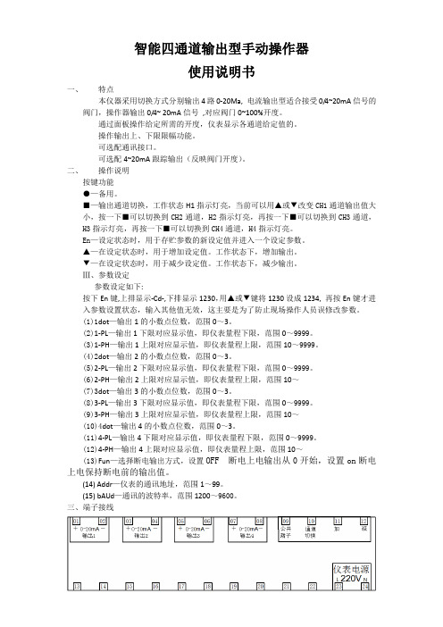
智能四通道输出型手动操作器使用说明书一、特点本仪器采用切换方式分别输出4路0-20Ma, 电流输出型适合接受0/4~20mA信号的阀门,操作器输出0/4~ 20mA信号,对应阀门0~100%开度。
通过面板操作给定所需的开度,仪表显示各通道给定值的。
操作输出上、下限限幅功能。
可选配通讯接口。
可选配4~20mA跟踪输出(反映阀门开度)。
二、操作说明按键功能●—备用。
■—输出通道切换,工作状态H1指示灯亮,当前可以用▲或▼改变CH1通道输出值大小,按一下■可以切换到CH2通道,H2指示灯亮,再按一下■可以切换到CH3通道,H3指示灯亮,再按一下■可以切换到CH4通道,H4指示灯亮。
En—设定状态时,用于存贮参数的新设定值并进入一个设定参数。
▲—在设定状态时,用于增加设定值。
工作状态下,增加输出。
▼—在设定状态时,用于减少设定值。
工作状态下,减少输出。
Ⅲ、参数设定参数设定如下:按下En键,上排显示-Cd-,下排显示1230,用▲或▼键将1230设成1234, 再按En键才进入参数设置状态,输入其他值无效,这主要是为了防止现场操作人员误修改参数。
(1)1dot—输出1的小数点位数,范围0~3。
(2)1-PL—输出1下限对应显示值,即仪表量程下限,范围0~9999。
(3)1-PH—输出1上限对应显示值,即仪表量程上限,范围10~9999。
(4)2dot—输出2的小数点位数,范围0~3。
(5)2-PL—输出2下限对应显示值,即仪表量程下限,范围0~9999。
(6)2-PH—输出2上限对应显示值,即仪表量程上限,范围10~(7)3dot—输出3的小数点位数,范围0~3。
(8)3-PL—输出3下限对应显示值,即仪表量程下限,范围0~9999。
(9)3-PH—输出3上限对应显示值,即仪表量程上限,范围10~(10)4dot—输出4的小数点位数,范围0~3。
(11)4-PL—输出4下限对应显示值,即仪表量程下限,范围0~9999。
- 1、下载文档前请自行甄别文档内容的完整性,平台不提供额外的编辑、内容补充、找答案等附加服务。
- 2、"仅部分预览"的文档,不可在线预览部分如存在完整性等问题,可反馈申请退款(可完整预览的文档不适用该条件!)。
- 3、如文档侵犯您的权益,请联系客服反馈,我们会尽快为您处理(人工客服工作时间:9:00-18:30)。
4 Y7
Y5
COM4FX2NPLC 高速脉冲输出的应用例程
本文适用机型:
具有同时输出4路高速脉冲的能力,支持的发脉冲指令有PLSY 、PLSR 、DRVI 三种。
最高输出频率为20K (100K 订货可选),允许同时输出互不影响。
相同编号的Y 输出点在梯形图中也允许多重驱动,方便用户编程。
以下就以DRVI 指令为例,介绍驱动4个步进马达驱动器的方法。
允许高速脉冲输出的点分别是Y0、Y1、Y6、Y7,与步进马达驱动器的接线如下:
脉冲输入端
方向输入端
步进马达驱动器电源负极端
步进马达驱动器1 Y0 Y2 COM0、COM2 步进马达驱动器2 Y1 Y3 COM1、COM2 步进马达驱动器3 Y6 Y4 COM3、COM2 步进马达驱动器、COM2
测试过程:
1, 写入梯形图到PLC 中,文件名为2N-DRVI 。
使PLC 进入RUN 状态。
2, 使X0 ON ;Y0输出500个脉冲,Y2 ON 正转。
使X1 ON ;Y0输出500个脉冲,
Y2 OFF 反转。
3, 使X2 ON ;Y1输出500个脉冲,Y3 ON 正转。
使X3 ON ;Y1输出500个脉冲,
Y3 OFF 反转。
4, 使X4 ON ;Y6输出500个脉冲,Y4 ON 正转。
使X5 ON ;Y6输出500个脉冲,
Y4 OFF 反转。
5, 使X6 ON ;Y7输出500个脉冲,Y5 ON 正转。
使X7 ON ;Y7输出500个脉冲,
Y5 OFF 反转。
PLSY 、PLSR 脉冲指令使用到的特殊元件如下:
Y0 Y1 Y6 Y7
发送结束标志 M8029 M8029 M8029 M8029 累计脉冲个数(32位) D8140、D8141
D8142、D8143
D8150、D8151 D8152、D8153
DRVI 脉冲指令使用到的特殊元件如下:
Y0 Y1 Y6 Y7
发送结束标志 M8029 M8029 M8029 M8029 当前位置值(32位) D8140、D8141D8142、D8143
D8150、D8151 D8152、D8153
执行时的加减速 时间(ms )
D8148 D8148 D8148 D8148
脉冲输出停止位 M8145 M8146 M8155 M8156 脉冲输出忙标志 M8147 M8148 M8157 M8158
注意事项:
1, Y6用于脉冲输出时,不能同时使用X0作为高速计数的输入。
2, Y7用于脉冲输出时,不能同时使用X3作为高速计数的输入。
FX2N-40MT PLC
1,Y0用于脉冲输出时,M8080要设为OFF,不能使用DA0-DA1的模拟量输出。
2,Y6用于脉冲输出时,不能使用X0作为高速计数的输入。
3,Y7用于脉冲输出时,不能使用X3作为高速计数的输入。
编程技巧问答:
提问:FX2N无法在梯形图编辑软件里输入DRVI指令,怎么办?
回答1:可以通过整行复制/粘贴在FX1N梯形图编辑软件里的DRVI指令到现在的FX2N 梯形图编辑软件里来解决。
回答2:改变PLC类型的方法:
1,由FX2N改到FX1N,这样就可以直接使用DRVI指令了。
改变D8101的值为26300,重新上电PLC就改变为FX1N。
2,由FX1N改到FX2N
改变D8101的值为24300,重新上电PLC就改变为FX2N。