CATIA DMU实例教程-加油口盖运动校核
CATIA_DMU机构运动分析新手教程

第五章DMU 机构运动分析1 第五章CATIA V5 DMU 机构运动分析目录1产品介绍 (4)2图标功能介绍(基本概念、基本界面介绍) (4)2.1DMU运动仿真(DMU Simulation)工具条 (4)2.2DMU运动副创建工具条(Kinematics Joints) (4)2.3DMU Generic Animation (5)2.4机构刷新(DMU Kinematics Update) (6)2.5干涉检查模式工具条(Clash Mode) (6)2.6DMU 空间分析(DMU Space Analysis) (6)3功能详细介绍 (7)3.1DMU运动仿真(DMU Simulation)工具条 (7)3.1.1用命令驱动仿真(Simulating with Commands) (7)3.1.2用规则驱动仿真(Simulating With Laws) (9)3.1.3仿真感应器(Sensors) (10)3.1.4机构修饰(Mechanism Dressup) (12)3.1.5创建固定副(Fixed Part) (12)3.1.6装配约束转换(Assembly Constraints Conver) (13)3.1.7测量速度和加速度(Speeds and Accelerations) (15)3.1.8机构分析(Mechanism Analysis) (17)3.2DMU运动副创建工具条(Kinematics Joints) (19)3.2.1创建转动副(Creating Revolute Joints)点击 (19)3.2.2创建滑动副(Creating Prismatic Joints) (20)3.2.3同轴副(Creating Cylindrical Joints) (21)3.2.4创建球铰连接(Creating Spherical Joints) (22)3.2.5创建平动副(Creating Planar Joints) (23)3.2.6创建刚性副(Rigid Joints) (24)3.2.7点-线副(Point Curve Joints) (24)3.2.8曲线滑动副(Slide Curve Joints) (25)3.2.9点-面副(Point Surface Joints) (26)3.2.10万向节(Universal Joints) (26)3.2.11C V连接(CV Joints) (27)3.2.12创建齿轮副(Gear Joints) (28)2 第五章CATIA V5 DMU 机构运动分析3.2.13滑动-转动复合运动副(Rack Joints) (30)3.2.14滑动-滑动复合运动副(Cable Joints) (32)3.2.15用坐标系法建立运动副(Creating Joints Using Axis Systems) (32)3.3DMU Generic Animation工具条 (34)3.3.1创建运动仿真记录(Simulation) (34)3.3.2生成重放文件(Generate Replay) (36)3.3.3重放(Replay) (37)3.3.4仿真播放器(Simulation Player) (37)3.3.5编辑序列(Edit Sequence) (37)3.3.6包络体(Swept Volume) (37)3.3.7生成轨迹线(Trace) (37)3.4机构刷新(DMU Kinematics Update) (38)3.4.1机构位置刷新(Update) (38)3.4.2输入子机构(Import Sub-Mechanisms) (38)3.4.3重设位置(Reset Positions ) (39)3.5干涉检查模式工具条(Clash Mode) (40)3.5.1关闭干涉检查(Clash Detection(Off) (40)3.5.2打开干涉检查(Clash Detection(On) (40)3.5.3遇到干涉停止(Clash Detection(Stop) (40)3.6DMU 空间分析(DMU Space Analysis) (40)3.6.1干涉检查(Clash) (40)3.6.2距离和距离带分析(Distance and band analysis) (40)3.7示例 (41)3 第五章CATIA V5 DMU 机构运动分析1 产品介绍DMU机构运动分析(Kin )是专门做DMU装配运动仿真的模块。
优选CATIA实用DMU运动仿真小教程

一、功能介绍
模块简介
功能键一览表
过程 将装配件导入DMU模块----建立机械装置----分析运动结合类型 ----建立运动结合----约束固定件----设置驱动形式----运动仿真
运动仿真有两种: 1、使用命令进行模拟 (可编辑传感器) 2、模拟 (可生成自动播放动画,也可编辑传感器)----可通 过编译模拟 ,生成重放 。
4. 固定零件
单机
中的 按钮,弹出右图所示窗口
,然后直接左键单击壳体part,这时系统会出现“可以模拟机
械装置”提示,点击确定
5、设置驱动形式
注意此时机械装置自由度=0,若不为0不能仿真 的,此项尤为重要。 修改: 下限改为-65°;上限改为0°
6、使用命令进行模拟
点击
中的 (使用命令
进行模拟)按钮,弹出右图所示窗口,电机“模
(4)其他约束 用旋转指令 将以下几个产品之间互相约束一起来。 ①、“波轮与连杆”;旋转副 ②、“连杆与风门连杆”;旋转副 ③、“风门连杆与壳体”;旋转副
壳体 波轮
连杆 命令在运动机构里面,点击其图标右下方的箭 头,点击后,选择图标
然后点击“风门连杆”跟“风门”
(3)约束 图中直线1、直线2、平面1、平面2,依次 选取壳体轴线、波轮轴线、壳体平面、波 轮平面,并单击“偏移”与“驱动角度”按 钮。单击确定
机械装置:运动机构名称 结合名称:运动副名称 直线1:波轮轴 直线2:壳体轴 平面1:破轮平面 平面2:壳体平面 驱动角度:点选可驱动波轮转动角度. (注意:驱动点选后自由度-1)
拟下的立刻”按钮,便可拖动上面的游标随意旋
转,也可使用“按需要”命令,修改一下右上角数
字框中的数据,就可点击下方的 箭头标示
CATIA DMU Kinematics Simulator运动模拟教程
Copyright DASSAULT SYSTEMES
Plane 1: select the left inner hinge plane Plane 2: select the left wheel surface
7:Assign the Angle driven command to the revolute joint if needed. 根据旋转联接需要选择角度驱动 8:Click Ok to end the revolute joint creation.The specification tree is updated accordingly: 点击OK结束旋转运动副创建 ,目录树随之更新
1
Create the Joints and eventually define the Laws创建联接和定义运动规律(运动性质)
2
OR… Convert Constraints, or V5 Mechanism转换约束或机构
3
Browse the Mechanism查看机构
5
Analyze the Results and Modify
Icon Name Revolute Prismatic Cylindrical Spherical Planar Rigid Roll Curve Slide Curve Point on Cuve Point Surface U Joint Gear joint Rack Joint Cable Joint Screw Joint CV Joint
整车运动分析、DMU校核
整车运动分析、DMU校核整车运动分析是整车DMU(数字化虚拟样机)分析的重要内容,主要目的是检查整车所有运动件在运动过程中与周边件的间隙合理性,校核内容包括底盘、车身、内外饰、附件。
报告由整车总布置科撰写及归档。
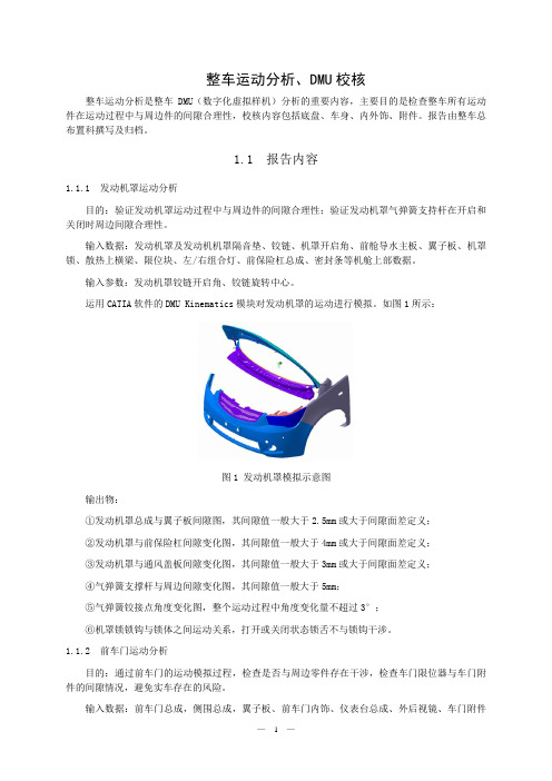
1.1 报告内容1.1.1 发动机罩运动分析目的:验证发动机罩运动过程中与周边件的间隙合理性;验证发动机罩气弹簧支持杆在开启和关闭时周边间隙合理性。
输入数据:发动机罩及发动机机罩隔音垫、铰链、机罩开启角、前舱导水主板、翼子板、机罩锁、散热上横梁、限位块、左/右组合灯、前保险杠总成、密封条等机舱上部数据。
输入参数:发动机罩铰链开启角、铰链旋转中心。
运用CATIA软件的DMU Kinematics模块对发动机罩的运动进行模拟。
如图1所示:图1 发动机罩模拟示意图输出物:①发动机罩总成与翼子板间隙图,其间隙值一般大于2.5mm或大于间隙面差定义;②发动机罩与前保险杠间隙变化图,其间隙值一般大于4mm或大于间隙面差定义;③发动机罩与通风盖板间隙变化图,其间隙值一般大于3mm或大于间隙面差定义;④气弹簧支撑杆与周边间隙变化图,其间隙值一般大于5mm;⑤气弹簧铰接点角度变化图,整个运动过程中角度变化量不超过3°;⑥机罩锁锁钩与锁体之间运动关系,打开或关闭状态锁舌不与锁钩干涉。
1.1.2 前车门运动分析目的:通过前车门的运动模拟过程,检查是否与周边零件存在干涉,检查车门限位器与车门附件的间隙情况,避免实车存在的风险。
输入数据:前车门总成,侧围总成,翼子板、前车门内饰、仪表台总成、外后视镜、车门附件总成、车门线束总成、三角窗等。
输入参数:前门铰链中心线后倾角度,内倾角度,前门全开角度(限位器)角度,铰链全开角度。
运用CATIA软件的DMU Kinematics模块对前车门的运动进行模拟。
如图2所示:图2 前车门运动模拟示意图输出物:①前车门总成和翼子板之间的运动间隙变化图,其最小间隙为2.5mm或为间隙面差定义的1/2;②前车门总成和车身上铰链之间的运动间隙变化图,其最小间隙为4mm;③前车门总成和车身下铰链之间的运动间隙变化图,其最小间隙为4mm;④车门限位器的运动轨迹及间隙变化图,车门限位器不与周边件干涉;1.1.3 后车门(滑移门)运动分析目的:通过后车门的运动模拟过程,检查是否与周边零件存在干涉,检查车门限位器与车门附件的间隙情况,避免实车存在的风险。
CATIADMU官方教程一

CATIADMU官方教程一D M U O p t i m i z e rD e t a i l e d S t e p sTable of ContentsNH90 Exercise (3)Step 1 (3)Step 2 (8)Step 3 (12)Step 4 (17)Step 5 (20)Step 6 (22)Step 7 (24)NH90 ExerciseStep 11. Compute SimplificationGo to the DMU Optimizer workbenchOpen the CATProduct : CATDMO_NH90_Step1.CATProduct ?Click on the Simplification iconThe Simplification dialog box appears:Select the NH90_linkage_rod_type-02Type an Accuracy of 3mmClick on the Preview button:The preview window appears:2. Save the Result as a CGR fileClick on the Save buttonSelect a directory and type a different name if youwant ?Click on the Save button of the Save As window The Simplification dialog box stays active3. Compute a multi-components SimplificationSelect others components like in the picture below(one by one or with a trap)Type an Accuracy of 5mmClick on the Preview button The result is displayed:Save it as a CGR file like previouslyClick on the Close button4. Replace the Simplified components by the CGR file just createdRemove these five components from the assemblyInsert the CGR file of the Simplification in the product5. Save the product under another nameGo to the menu File / Save As…Type a new nameClick on SaveStep 26. Compute SilhouetteOpen the CATProduct : CATDMO_NH90_Step2-4.CATProduct Select the Silhouette View in the Named Views panelThis viewpoint is the one, which will be used for the silhouette view 7. Compute and save the silhouetteSelect the Silhouette iconSelect the helicopter for the Selection fieldEnter 50mm for the Accuracy parameterSelect the viewpoint Silhouette View from the Multi-selection List panel then Click OKLaunch the computation by clicking on the Preview buttonIt takes about one minute and half to compute the silhouette with this accuracy ?The preview window display the result Click on the Save buttonYou are asked to save the silhouette in a directory: Save itNote that the resulting file is a tessellated file format (. cgr) Click on the Close button8. Create a scene with the silhouette duplicated several timesClose all the windows in CATIAGo to the DMU Navigator workbenchInsert as an existing component the silhouette you have just createdYou can inspect the silhouette as you wishWithin the Product, copy and paste the helicopter several times,And use the 3D Compass to move the copiesYou can create a scene with 4 or 5 helicopters parked together9. Information about the reduction of sizeSize of the original model: 15.7 MBSize of the tessellated file: 7.8 MBNumber of triangles: 463.000Size of the silhouette: 3.4 MBNumber of triangles: 229.000Step 310. Compute WrappingGo to the DMU Optimizer workbenchOpen the CATProduct : CATDMO_NH90_Step3.CATProduct Select the view View for Wrapping in the Named Views panel This viewpoint is the one which will be used for the Wrapping computation11. Compute the Wrapping representation and substitute it to the originalSelect Tools -> OptionsSelect DMU Optimizer in the left-hand boxSelect the DMU Optimizer tabSwitch the Manage as alternate shape option on for Wrapping ?Check that Activate shape option is onCheck that D efault shape option is offClick OKSelect the Wrapping iconSelect the landing gear for the Selection fieldPut the Grain value to 50 mmPut the Ratio to 0.0Click PreviewNote that the wrapping representation is replacing the original model in the session, because the Activate Shape option is on in the DMU Optimizer tabMake some tests by changing the parameters Grain,Ratio or Cubic, with Preview button to compute the new representation Click Save when you are satisfied with the wrapping representationYou are asked to save the wrapping representation (cgr file) Re-compute on another component or click CloseStep 412. Compute ThicknessGo to the DMU Optimizer workbenchOpen the CATProduct : CATDMO_NH90_Step2-4.CATProduct13. Prepare the options for the resultTurn the option Manage as an alternate shape on for Thickness14. Compute and visualize the thicknessSelect the Thickness iconSelect the NH90 skin for the Selection fieldEnter 5 mm for the Offset1 fieldEnter 0 mm for the Offset2 fieldClick Preview to start the computationYou can manipulate the new representation as you wish15. Analyse the new representation (volume)Select the Measure item iconClick on the NH90 skin with its new thicknessYou get the volume of the NH90 skin with a thickness of 5 mm (for example with composites structures)Close the Measure item panelYou can try several thicknesses and re-start the computation, then compare the volumesTo go further in this functionnality, you can put some orientation constraints to the faces with a wrong orientation, and re-start the computation。
CATIA DMU运动分析校核技巧

长城汽车
CATIA DMU 运动分析校核技巧 1、 现在脑子里把整个运动过程想一遍,想清楚,分析出主要的运 动骨架是什么。
2、 加约束,将各部件位置关系确定好,如前悬架的定位参数,否 则最后做出来的分析结果没有意义。
3、 做好各部件连接处的辅助点、线、面,为下一步加运动副做准 备。
4、 从运动终端开始加运动副,逐渐往驱动部件方向走,尽量保证 在加下一个运动副之前已加运动副部件能运动,一句话——先 把骨骼建立起来再往上面一点点添肉。
最后,DMU 运动分析要求我们的思路非常清晰,稍有差错就可能前 功尽弃,具体说就是目录树规范,不仅自己很清楚,给别人看也能一 目了然, 再有就是加运动副的顺序, 自己可以归纳出自己的一套方法, 目的是思路清晰不漏项。
以上是我经过一年的使用总结出来的,希望和大家共勉,我的邮箱是 icedian@,很想听听各位前辈的经验之谈。
哈弗 CUV
全能无界 自由无限
。
catiaDMU运动机构解读

CATIA数字样机仿真机构分析CATIA数字样机仿真机构分析 (1)绪论 (2)细节分析 (3)运动仿真的流程 (4)相关概念 (5)重点一一理解各运动副的概念和创建要素 (7)基本运行与位置调整 (10)基于运动函数的模拟 (10)综合模拟 (11)序列编辑与重放 (13)基于运动仿真的数字样机分析 (14)运动副运动规律的查看与保存 (15)运动参数测量 (15)机构运动轨迹分析 (16)扫掠包络体 (17)空间分析 (18)绪论相对于物理样机,数字样机的优点不言而喻,在很大程度上可以代替物理样机的作用,随着数字样机技术的发展和日益成熟,今后会在更大的程度和更多的方面取代物理样机,提高产品的研发效率和技术水平。
学习Catia数字样机需要掌握主要几大块内容:1、工作窗口的构成和功能2、运动仿真流程的掌握3、各种运动副的运用4、基本运动学原理的掌握5、仿真机构的运行与重放6、基于运动仿真的数字样机分析技术细节分析该模块位置:CATIL Digital Mock Up — DMU kin ematicsDMU Generk Animation DMU-般动画各工具按钮的作用需要在实践操作中一步步掌握和数字, 非一朝一夕 的功夫可以消化,其基本功能都是相对简单的,但是要综合运用,必 须勤加练习细细领悟。
运动仿真的流程工具栏主要:有DMU 运动机构Kinematics运动机构更新 四大块。
以及DMI 空间分析3D数字模型—数字样机准备—静态装配(包括全面静态装配后删除限制运动的约束后自动创建运动副、全面静态装配后通过对话框利用相关约束手动创建运动副)或者直接手动创建运动副—所有必要基础运动副创建完成—分析是否需要建立关联运动副并创建—定于仿真过程中的固定件(机械装置自由度DOF变为1)—施加驱动&制定运动法则(直到机械装置自由度DOF为0)—运动模拟与分析。
相关概念1、完整的静态约束:具有装配关系的两个零部件间有3个能够限制或者规定其3D空间全部自由度的约束,保证数字样机上每一个零部件均具有空间中的唯一位置。
整车运动分析、DMU校核
整车运动分析、DMU校核整车运动分析是整车DMU(数字化虚拟样机)分析的重要内容,主要目的是检查整车所有运动件在运动过程中与周边件的间隙合理性,校核内容包括底盘、车身、内外饰、附件。
报告由整车总布置科撰写及归档。
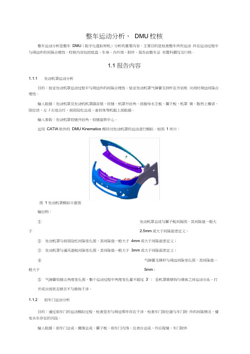
1.1 报告内容1.1.1 发动机罩运动分析目的:验证发动机罩运动过程中与周边件的间隙合理性;验证发动机罩气弹簧支持杆在开启和关闭时周边间隙合理性。
输入数据:发动机罩及发动机机罩隔音垫、铰链、机罩开启角、前舱导水主板、翼子板、机罩锁、散热上横梁、限位块、左/ 右组合灯、前保险杠总成、密封条等机舱上部数据。
输入参数:发动机罩铰链开启角、铰链旋转中心。
运用CATIA软件的DMU Kinematics 模块对发动机罩的运动进行模拟。
如图1 所示:图1 发动机罩模拟示意图输出物:①发动机罩总成与翼子板间隙图,其间隙值一般大于 2.5mm或大于间隙面差定义;②发动机罩与前保险杠间隙变化图,其间隙值一般大于4mm或大于间隙面差定义;③发动机罩与通风盖板间隙变化图,其间隙值一般大于3mm或大于间隙面差定义;④气弹簧支撑杆与周边间隙变化图,其间隙值一般大于5mm;⑤气弹簧铰接点角度变化图,整个运动过程中角度变化量不超过3°;⑥机罩锁锁钩与锁体之间运动关系,打开或关闭状态锁舌不与锁钩干涉。
1.1.2 前车门运动分析目的:通过前车门的运动模拟过程,检查是否与周边零件存在干涉,检查车门限位器与车门附件的间隙情况,避免实车存在的风险。
输入数据:前车门总成,侧围总成,翼子板、前车门内饰、仪表台总成、外后视镜、车门附件—1 —总成、车门线束总成、三角窗等。
输入参数:前门铰链中心线后倾角度,内倾角度,前门全开角度(限位器)角度,铰链全开角度。
运用CATIA软件的DMU Kinematics 模块对前车门的运动进行模拟。
如图 2 所示:图2 前车门运动模拟示意图输出物:①前车门总成和翼子板之间的运动间隙变化图,其最小间隙为 2.5mm或为间隙面差定义的1/2 ;②前车门总成和车身上铰链之间的运动间隙变化图,其最小间隙为4mm;③前车门总成和车身下铰链之间的运动间隙变化图,其最小间隙为4mm;④车门限位器的运动轨迹及间隙变化图,车门限位器不与周边件干涉;1.1.3 后车门(滑移门)运动分析目的:通过后车门的运动模拟过程,检查是否与周边零件存在干涉,检查车门限位器与车门附件的间隙情况,避免实车存在的风险。
- 1、下载文档前请自行甄别文档内容的完整性,平台不提供额外的编辑、内容补充、找答案等附加服务。
- 2、"仅部分预览"的文档,不可在线预览部分如存在完整性等问题,可反馈申请退款(可完整预览的文档不适用该条件!)。
- 3、如文档侵犯您的权益,请联系客服反馈,我们会尽快为您处理(人工客服工作时间:9:00-18:30)。
加油口盖运动校核步骤
1.将所需要数据(将运动件装在一个总成下)装配完成后进入DMU运动机构模块熟悉DMU工具条
查看机构转换约束或机构
创建联接和定义运动规律(运动性质)
2.在销轴上和加油口盖内板上各做一条和轴线重合的直线(重合)
选择螺孔接头
3. 选择需固定的件,点确定。
点确定
Applications
4.选择
双击机制.1
选择设置角度点确定
将左下角按钮由0度拖动到设定的角度(-90°),并点右侧的插入,再点确定就完成此模拟的创建,机构可以运动。
5. 选择刚性接头点确定
6. 确定
7.双击机制
选择
OK 测量
DMU.xls。