IFI-524-2002 非金属预置扭矩螺钉防松性能测试程序 公制系列
ifi524标准

ifi524标准
IFI 524标准是什么?
IFI 524是美国螺纹工业联合会(IFI)制定的一种标准,关于标准:
1. IFI 524标准是什么?
IFI 524标准是一种针对螺纹件的标准,为了确保螺纹工业的生产和使用的安全与规范。
2. IFI 524标准的作用是什么?
IFI 524标准的主要作用是建立统一的技术规范,增强螺纹件的生产和使用的安全性和规范性,促进螺纹工业的发展。
3. IFI 524标准的范围是什么?
IFI 524标准的适用范围包括线性和非线性螺纹的标准规格、尺寸、材料和引用。
4. IFI 524标准的具体要求是什么?
IFI 524标准的具体要求主要包括螺纹件的尺寸、标记、方法、用途、材料、力学性能以及质量要求等。
如果您需要了解IFI 524标准的具体细节,请参考IFI官方网站或咨询IFI认证机构,详细了解IFI 524标准的具体要求,以便更好地应用在
实践中。
总之,IFI 524标准作为一种螺纹工业标准,为螺纹件的生产和使用提供了规范和保障,促进螺纹工业的发展和进步。
我们应该认真对待IFI 524标准,广泛推广应用IFI 524标准,使之成为我们螺纹工业的标志。
紧固件防松措施及防松试验方法拧紧试验方法

紧固件防松措施及防松试验方法、拧紧试验方法 针对螺纹紧固件松动的问题,人们采取各种积极有效的措施,为螺纹紧固件的发展注入新的活力。
从各种标准和文献中可以看到,螺纹紧固件防松技术和防松结构很多,总结起来主要包括摩擦防松、直接锁紧、破坏运动副关系和粘结等几类方法。
(一)摩擦防松1.控制预紧力控制安装预紧力是防止螺纹紧固件松动的经济有效措施之一,这种方法利用螺纹的自锁条件,不需要对螺栓、螺母结构做任何改动,通过保证合适的预紧力来防松。
对于安装控制要求特别高的使用场合,采用直接控制的方法,在安装过程中测量预紧力,并加以控制,目前常用的方法有采用带测力装置的安装机,如液压安装机,对螺栓施加规定的轴向负荷,使其产生弹性变形,在旋紧螺母,完成装配。
也有采用测量螺栓应力或应变形的方法测定预紧力,据此进行安装控制。
一般情况下,直接控制安装预紧力需要使用专门的装置或掌握专门的技术,难予推广。
为了以经济的方法获得满意的预紧力,更多的采取间接测量和控制预紧力的方法,即扭矩控制法。
扭矩控制法通过扭矩系数将预紧力换算成装配扭矩,使用定扭矩或测扭矩装配机或扳手控制装配扭矩,或利用紧固件自身结构保证拧紧扭矩(如扭剪型螺栓连接副),间接达到控制预紧力的目的。
为了达到预期的目的,要求连接副的扭矩系数能预先准确测定,并保证同批零件的扭矩系数离散性不大。
如,GB/T1231-1991中明确规定同批连接副的扭矩系数平均值为 0.110-0.150,扭矩系数标准偏差应小于或乖于 0.001%。
在工程实践中,也有采用转角法、屈服点拧紧法等控制方法的。
2.有效力矩型紧固件有效力矩型紧固件是在普通紧固件结构基础上增加了有效力矩部分,其作用是在连接副中增加一个不随外力变化的阻力矩。
有效力矩部分主要是加在螺母上,在外螺纹上加有效力矩部分的产品比较少见。
全金属有效力矩型锁紧螺母,一类是利用螺母体上螺纹加工完成后螺母体变形,使螺纹发生轴向或径向变形,造成装配时内外螺纹局部出现干涉产生有效力矩,由于受变形量和变形前毛坯变形阻力和几何精度的影响,对加工工艺要求高,有效力矩控制难度大;另一类是将有效力矩部分减薄,收口或开槽后收口,目前国内主要在军工行业使用较多;第三类是在螺母体内嵌入金属弹性元件,装配时外螺纹迫使弹性元件变形,产生有效力矩,这类螺母对弹性元件弹性及嵌件的位置的要求较高,有时会划伤外螺纹表面。
紧固件防松性能检测方法及标准研究
紧固件防松性能检测方法及标准研究摘要:螺栓等紧固件是航空航天、轨道交通、机械等领域设备的重要零部件,其将多个零部件连接在一起从而组成一个新系统,是主要的连接方式之一,其防松性能对设备的安全运行具有重要作用。
螺栓类紧固件是一种可拆卸的连接方式,具有可更换等优点,但也造成易松动的特点,所以其使用前需要检测防松性能。
目前国内外检测螺栓紧固件防松性能的试验方法主要有地脚螺栓法、加速振动法、横向振动法,而后两种方法应用最普遍。
关键词:紧固件;防松性能;检测方法;标准;引言拧紧螺纹螺栓时,90%的扭矩用于克服摩擦力,10%用于转换为轴向夹紧力。
确定摩擦系数后,摩擦力大小和轴向夹紧力按照摩擦力=压力x摩擦系数的公式呈正相关,摩擦力直接影响螺栓承受横向载荷的能力。
因此,当螺纹连接处于极端困难的工作环境(例如剧烈振动、温度变化等)中时。
,螺纹联接由于摩擦系数的变化、振动、外部可变载荷等因素而不断丢失轴向夹紧力。
,直接导致摩擦力逐渐减弱。
当用作螺栓的横向应力超过螺纹对的摩擦力时,螺栓和连接器会相对于彼此移动,并且连接器对会逐渐变弱和退化,从而变得松散和松弛。
最终,防松螺纹联接的关键是防止螺纹对的相对旋转。
1紧固件防松原理及措施紧固件是将两个或两个以上的部件连接为一体所采用的机械零部件的总称,其中螺栓类紧固件在所有连接方式中的应用最普遍。
一是由于其螺栓紧固件连接比较可靠,其防松性能较好,具有较高的可靠性;二是螺栓紧固件的连接方式具有可拆卸性,基本不会破坏被连接件的使用性能,更换方便。
螺栓类紧固件是通过螺纹的方式连接多个部件,在被连接件上施加轴向紧固力,再通过螺纹之间的摩擦力防止螺纹松脱,从而达到连接并紧固零部件的目的。
正常应用情况下,由于轴向紧固力的施加,螺纹之间产生弹性变形,并且轴向力转换为螺纹接触面之间的摩擦力;被连接件松动的力和与螺纹之间的摩擦力达到平衡状态,紧固件处于锁紧状态。
但当紧固件受到振动等外力作用时,一方面,螺纹连接面可能发生塑性变形,消耗一部分紧固力;另一方面,外力会导致螺栓连接面的摩擦力平衡状态被破坏,螺纹连接面移动,最终导致紧固件松动。
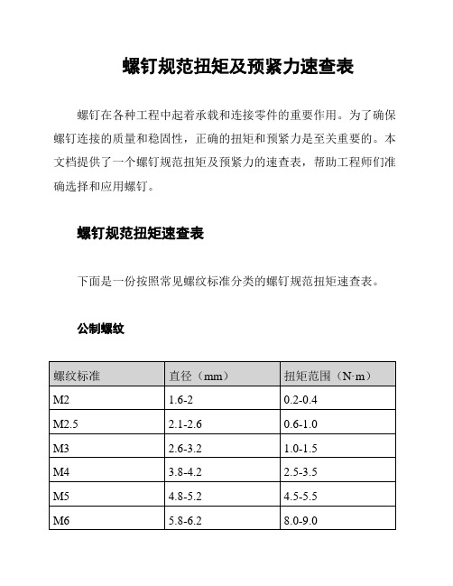
螺钉规范扭矩及预紧力速查表
螺钉规范扭矩及预紧力速查表
螺钉在各种工程中起着承载和连接零件的重要作用。
为了确保螺钉连接的质量和稳固性,正确的扭矩和预紧力是至关重要的。
本文档提供了一个螺钉规范扭矩及预紧力的速查表,帮助工程师们准确选择和应用螺钉。
螺钉规范扭矩速查表
下面是一份按照常见螺纹标准分类的螺钉规范扭矩速查表。
公制螺纹
英制螺纹
注意:以上数值仅为参考,实际扭矩应根据具体情况进行调整。
螺钉预紧力速查表
下面是一份按照常见螺纹标准分类的螺钉预紧力速查表。
公制螺纹
英制螺纹
注意:以上数值仅为参考,实际预紧力应根据具体情况进行调整。
*注意:以上内容仅供参考,请根据具体需求和实际情况进行确认和调整。
*。
螺栓防松的形式与注意事项

不可缺失;
C线叉载升降机导 向轮螺栓
双螺母
对顶螺母防松 利用螺母对顶作用使螺栓式中受
到附加的拉力和附加的摩擦力。由于多用一个螺母, 并且工作不十分可靠,目前已经很少使用。
C线叉载升降机链条在 升降架上固定螺栓
开口销防松 双重保障
开口销
槽形螺母和开口销防松 槽形螺母拧紧后,
SGMW机密 Confidential
螺栓防松的形式及注意事项
2016-2-12
防松的分类
摩擦防松
1、弹簧垫片 2、自锁螺母 3、双螺母
受冲击力情况下容易松脱,需要 用记号笔做好防松标示,易于检 查;相关部件不能够缺失;
可拆卸防松
1、开口销
防 松
机械防松
2、开槽螺母 2、止动垫片
机械防松的方法比较 可靠,对于重要的联 接要使用机械防松的 方法;
用开口销穿过螺栓尾部小孔和螺母的槽,也可 以用普通螺母拧紧后进行配钻销孔。
气缸头与夹头 的连接处
气缸杆与气缸头的连接 处,防止相对转动,脱
丝,不可缺失
开槽螺母
X
老A线叉载升降机 导向轮螺栓
串接钢丝
串联钢丝防松 用低碳钢钢丝穿入各螺钉头部的孔内,将各螺钉串联起来,使其相互 制动。这种结构需要注意钢丝穿入的方向;
止动垫片
止动垫片 螺母拧紧后,将单耳或双耳止动垫圈分别向螺母和被联接件的侧面折弯贴 紧,实现防松。如果两个螺栓需要双联锁紧时,可采用双联止动垫片。
开口销
圆螺母和止动动垫片 使垫圈内舌嵌入螺栓(轴)的槽内,拧紧 螺母后将垫圈外舌之一褶嵌于螺母的一个槽内。
内舌卡到轴的槽里面,外 舌卡到丝目的槽里面
永久防松
美国最新紧固件标准IFI第七版中英文对照目录

A部分:螺纹ANSI/ASME B1.7M 1984(R2001)NOMENCLATURE,DEFINITIONS,AND LETTER SYMBOLS FORSCREW THREADS螺纹的术语、定义和字母代号ASME B1.1 2003 UNIFIED INCH SCREW THREADS(UN AND UNR THREAD FORM)统一英制螺纹(UN和UNR螺纹形状) ASME B1.3M 1992(R 2001) SCREW THREAD GAGING SYSTEMS FOR DIMENSIONALACCEPTABILITY-INCH SCREW THREADS(UN,UNR,AND UNJ)尺寸接受的螺纹测量系统英制和米制螺纹(UN, UNR, 和UNJ)ANSI/ASME B1.2 1983(R2001)GAGES AND GAGING FOR UNIFIED INCH SCREW THREADS 统一螺纹的量规和测量ASME/ANSI B1.121987(R2003)CLASS 5 INTERFERENCE-FIT THREAD 第5级过盈配合螺纹ASME B1.15 1995 UNIFIED INCH SCREW THREADS(UNJ THREAD FORM) 统一英制螺纹(UNR螺纹形状) B部分:材料和涂镀IFI SELECTING FASTENER MATERIAL 紧固件材料选择IFI BOLT AND NUT COMPATIBILIITY 螺栓和螺母的匹配IFI CORROSION 腐蚀作用IFI PLATINGS AND COATINGS 镀层和涂层IFI-140 2000 CARBON AND ALLOY STEEL WIRE,RODS,AND BARS FORMECHANICAL FASTENERS用于机械紧固件的碳素钢和合金钢的线材,圆钢,钢棒SAE J429 1999 MECHANICAL AND MATERIAL REQUIREMENTS FOREXTERNALLY THREADED FASTENERS外螺纹紧固件的机械和材料要求ASTM A307 2004 Standard Specification for Carbon Steel Bolts and Studs, 60 000 PSI TensileStrength碳素钢外螺纹紧固件ASTM A449 2004b Specification for Hex Cap Screws, Bolts, and Studs, Steel, Heat Treated,120/105/90 ksi Minimum Tensile Strength, General Use经淬火和回火的钢制螺栓和螺柱ASTM A320/A320M-2005a ALLOY STEEL BOLTING MATERIALS FOR LOW TEMPERATURESERVICE低温用合金钢和不锈钢螺栓材料ASTM A193/A193M-2006 Alloy-Steel and Stainless Steel Bolting Materials for High Temperature orHigh Pressure Service and Other Special Purpose Applications高温高压用合金钢和不锈钢螺栓材料ASTM A194/A194M-2006b CARBON AND ALLOY STEEL NUTS FOR BOLTS FOR HIGHPRESSURE OR HIGH TEMPERATURE SERVICE,OR BOTH高压或高温作业或者高压高温作用用螺栓的碳钢和合金钢螺母ASTM A354-2004 QUENCHED AND TEMPERED ALLOY STEEL BOLTS,STUDS,ANDOTHER EXTERNALLY THREADED FASTENERS淬火和回火合金钢螺栓、双头螺栓和其它外螺纹紧固件ASTM F593-2002e2 STAINLESS STEEL BOLTS,HEX CAP SCREWS,AND STUDS 不锈钢螺栓、六角帽螺钉和柱头螺栓ASTM F468-2006 NONFERROUS BOLTS,HEX CAP SCREWS,AND STUDS FORGENERAL USE普通有色金属螺栓、六角帽螺钉和螺柱ASTM A563-2004a CARBON AND ALLOY STEEL NUTS 碳素钢和合金钢螺母ASTM F594 2002 STAINLESS STEEL NUTS 不锈钢螺母ASTM F467-2006 NONFERROUS NUTS FOR GENERAL USE 通用非金属螺母ASTM F788/F788M-2006 Surface Discontinuities of Bolts, Screws, and Studs, Inch and Metric Series 螺栓、螺钉和螺栓表面缺陷ASTM F812/F812M-2003 Standard Specification for Surface Discontinuities of Nuts, Inch and MetricSeries螺母表面缺陷ASTM F606-2006 TEST METHODS FOR DETERMINING THE MECHANICALPROPERTIES OF EXTERNALLY AND INTERNALLY THREADEDFASTENERS,WASHERS,AND RIVETS测定外螺纹和内螺纹紧固件、垫圈及铆钉机械性能的试验方法ASTM B633-1998e1 ELECTRODEPOSITED COATINGS OF ZINC ON IRON AND STEEL钢铁表面电解沉积锌镀层ASTM A153/A153M-2005 ZINC COATING(HOT-DIP)ON IRON AND STEEL HARDWARE 钢铁构件镀锌层(热浸)ASTM B695-2004 COATINGS OF ZINC MECHANICALLY DEPOSITED ON IRON ANDSTEEL钢铁表面锌机械沉积镀层ASTM B696-2000(2004)e1 COATINGS OF CADMIUM MECHANICALLY DEPOSITED 镉机械沉积锌镀层ASTM B766-1986(2003) ELECTRODEPOSITED COATINGS OF CADMIUM 镉电沉积镀层ASTM F1135-1999(2004) CADMIUM OR ZINC CHROMATE ORGANIC CORROSIONPROTECTIVE COATINGS FOR FASTENERS紧固件用铬酸镉或锌有机防蚀镀层ASTM F1136-2004 CHROMIUM/ZINC CORROSION PROTECTIVE COATINGS FORFASTENERS紧固件用铬/锌防蚀镀层ASTM F1137 2000 PHOSPHATE/OIL AND PHOSPHATE/ORGANIC CORROSIONPROTECTIVE COATINGS FOR FASTENERS紧固件用磷酸盐/油和磷酸盐/有机防蚀镀层ASTM F1941-2000 ELECTRODEPOSITED COATINGTS ON THREADED FASTENERS[UNIFIED INCH SCREW THREADS(UN/UNR)]螺纹紧固件上电镀层[统一英寸制螺纹(UN/UNR)]C部分:螺栓、螺钉和螺柱ASME B18.2.1 1996 SQUARE AND HEX BOLTS AND SCREWS(INCH SERIES) 正方型和六角型螺栓和螺钉(英制系列) IFI-149 2000 LARGE SIZE HEAVY HEX SCREWS 大规格大六角螺钉IFI-111 2002 HEX FLANGE SCREWS 六角法兰螺钉IFI-115 2002 FLANGE 12-POINT SCREWS 12角法兰螺钉ASME B18.5-1990(R2003) ROUND HEAD BOLTS 圆头螺栓ASME B18.9-1996(R2003) PLOW BOLTS(INCH SERIES) 防松螺栓ANSI/ASME B18.10 1982(R2000)Track Bolts and Nuts 轨道螺栓和螺母;ASME B18.15-1985(R2003) FORGED EYEBOLTS 锻造环眼螺栓IFI-136 2002 STUDS AND BENT BOLTS 螺柱和螺栓ASME B18.6.2 1998 Slotted Head Cap Screws 开槽平头螺钉IFI-148 2002 THREADED PROJECTION WELD STUDS 焊接螺柱D部分:螺母IFI Commentary ON NUTS 螺母的解释和说明ASME/ANSI B18.2.2 1987(R SQUARE AND HEX NUTS 方型和六角螺母1999)IFI-145 2002 HEX FLANGE NUTS AND LARGE HEX FLANGE NUTS 六角法兰螺母和大规格六角法兰螺母IFI-128 2000 HEX COUPLING NUTS 六角轴接螺母ANSI/ASME B18.10 1982(R2000)TRACK BOLTS 轨道螺栓及螺母ASME B18.6.3-2003 SQUARE AND HEX MACHINE SCREW UNTS 方型和六角机器螺母ASME B18.6.X DRAFTSTANDARD 2002WING NUTS 蝶形螺母E部分:高强度结构螺栓IFI COMMENTARY ON HIGH STRENGTH STRUCTURAL BOLTING 高强度结构螺栓的解释和说明ASME B18.2.6-1996(R2004) FASTENERS FOR USE IN STRUCTURAL APPLICATIONS 用于结构应用的紧固件ASTM A325-2006 STRUCTURAL BOLTS,STEEL,HEAT TREATED,120/105 KSIMINIMUN TENSILE STRENGTH经热处理的最小抗拉强度为120/105ksi的结构用钢螺栓ASTM A490-2006 STRUCTURAL BOLTS,ALLOY STEEL,HEAT TREATED,150 KSIMINIMUN TENSILE STRENGTH经热处理的最小抗拉强度为150 ksi的合金钢结构用螺栓ASTM A394-2005 STEEL TRANSMISSION TOWER BOLTS,ZINC COATED AND BEAR输电塔镀锌螺栓和裸螺栓ASTM F901 2001 ALUMINUN TRANSMISSION TOWER BOLTS AND NUTS 外科移植用精制钴铬钨镍合金ASTM F1852-2005 TWIST OFF TYPE TENSION CONTROL STRUCTURALBOLT/NUT/WASHER ASSEMBLIES,STEEL,HEAT TREATED 120/150KSI MINIMUM TENSILE STRENGTH经热处理的120/105ksi最小抗张强度拧松式张力控制结构钢螺栓/螺母/垫圈组件ASTM F959-2005a COMPRESSIBL-WASHER-TYPE DIRECT TENSION INDICATORSFOR USE WITH STRUCTURAL FASTENERS与结构紧固件一起使用的可压缩垫圈型直接拉力指示器F部分:有效力矩紧固件IFI AN INTRODUCTION TO LOCKING FASTENERS 锁紧紧固件的介绍IFI-100/107 2002 PREVAILING-TORQUE TYPE STEEL HEX AND HEX FLANGE NUTS 有效力矩型钢六角螺母和六角法兰螺REGULAR AND LIGHT HEX SERIES 母,常规小尺寸六角系列IFI-124 2002 TEST PROCEDURE FOR THE PERFORMANCE OF NONMETALLICRESISTANT ELEMENT PREVAILING-TORQUE SCREWSIFI-125 2002 TEST PROCEDURE FOR THE PERFORMANCE OF CHEMICALCOATED PREVAILING-TORQUE SCREWSIFI-155 2002 TEST PROCEDURE FOR THE PERFORMANCE OF NONMETALLICRESISTANT ELEMENT PREVAILING-TORQUE NUTS非金属嵌件有效力矩型螺母的性能测试程序IFI-143 2002 TEST FOR EVALUATING THE TORQUE-TENSION RELATIONSHIPON BOTH EXTERNALLY AND INTERNALLY THREADEDFASTENERS评测内外螺纹紧固件扭矩-拉伸关系的试验方法G部分:凹头螺钉ASME B18.3-2003 SOCKET CAP,SHOULDER,SET SCREWS,HEX,AND SPLINE KEYS六角和键槽圆柱头内六角带肩紧定螺钉ASTM A574-2004 ALLOY STEEL SOCKET HEAD CAP SCREWS 合金钢内六角螺钉ASTM F835-2004 ALLOY STEEL SOCKET BUTTON AND FLAT COUNTERSUNKHEAD CAP SCREWS合金钢凹圆头螺钉和平埋头帽螺钉ASTM F912-2004 ALLOY STEEL SOCKET SET SCREWS 合金钢凹头固定螺钉ASTM F879-2002a STAINLESS STEEL SOCKET BUTTON AND FLAT COUNTERSUNKHEAD CAP SCREWS不锈钢管座凸头及扁平埋头六角螺钉ASTM F880-2002 STAINLESS STEEL SOCKET SET SCREWS 不锈钢凹头螺钉H部分:自攻螺钉IFI AN INTRODUCTION TO TAPPING SCREWS 自攻螺钉的介绍ASME B18.6.4 1998 THREAD FORMING AND THREAD CUTTING TAPPING SCREWSAND METALLIC DRIVE SCREWS螺纹成型和螺纹切削自攻螺钉和金属传动螺杆SAE J933 1998 MECHANICAL AND QUALITY REQUIREMENTS FOR TAPPINGSCREWS自攻螺钉的机械和质量要求SAE J81 1997 THREAD ROLLING TAPPING SCREWS 滚制螺纹自攻螺钉SAE J78 1998 SELF-DRILLING TAPPING SCREWS 自钻自攻螺钉I部分:机螺钉ASME B18.6.3 2002 SLOTTED AND RECESSED HEAD MACHINE SCREWS;开槽和凹头机螺钉IFI-138 2002 STRAIGHTNESS GAGING METHOD AND STRAIGHTNESS LIMITSFOR MACHINE,TAPPING,AND THREAD ROLLING SCREWS机械,自攻和滚动螺纹的直线度测量方法J部分:其它小型螺钉ASME B18.6.2 1998 SQUARE HEAD AND SLOTTED HEADLESS SET SCREWS 开槽平头螺钉和开槽无头紧定螺钉ASME B18.13 1996 SCREW AND WASHER ASSEMBLIES——SEMS 螺钉和垫圈组件IFI-156 2002 THUMB SCREWS AND WING SCREWS 滚花和蝶形螺钉ASME B18.6.1 1981(R 1997) WOOD SCREWS 木螺钉ASME B18.11 1961(R 2000) MINIATURE SCREWS 小型螺钉K部分:铆钉ASME B18.1.2 1972(R 2001) LARGE RIVETS 1/2 IN.NOMINAL DIAMETER AND LARGER 大铆钉(公称直径1/2英寸及以上) ASME B18.1.1 1972(R 2001) SMALL SOLID RIVETS 7/16 IN.NOMINAL DIAMETER ANDSMALLER小型实心铆钉(公称直径7/16英寸及以下)ASME B18.7 1972(R 2001) GENERAL PURPOSE SEMI-TUBULAR RIVETS,FULL TUBULARRIVETS,SPLIT RIVETS AND RIVET CAPS通用半空心铆钉,空心铆钉,开口铆钉,铆钉盖IFI-110 2003 GLOSSARY OF TERMS RELATING TO BLIND RIVETS 盲孔铆钉相关专业词汇IFI-114 2003 BREAK MANDREL BLIND RIVETS 抽心铆钉IFI-117 2003 PULL THROUGH MANDREL BLIND RIVETS 带心轴盲孔铆钉IFI-119 2003 STRUCTURAL FLUSH BREAK PULL MANDREL SELF-PLUGGINGBLIND RIVETSIFI-123 2003 DRIVE PIN BLIND RIVETSIFI-126 2003 BREAK MANDREL CLOSED END BLIND RIVETS 抽心沉头铆钉IFI-130 2003 STRUCTURAL SPLITTING SELF-PLUGGING PULL MANDRELBLIND RIVETSIFI-134 2003 MULTI-GRIP FLUSH BREAK PULL MANDREL SELF-PLUGGINGBLIND RIVETSIFI-135 2003 MECHANICAL TESTING OF BLIND RIVETS 盲孔铆钉的机械测试IFI-137 2003 INSPECTION AND QUALITY ASSURANCE FOR GENERALPURPOSE BLIND RIVETS通用盲孔铆钉的说明和质量保证L部分:垫圈和销ASME B18.22.1-1965(R2003) PLAIN WASHERS 平垫圈ASME B18.21.1 1999 LOCK WASHERS 锁紧垫圈ASME B18.2.6 BEVELED WASHERS 斜垫圈ASTM F844-2004 Standard Specification for Washers, Steel, Plain (Flat), Unhardened forGeneral Use未淬火的钢垫圈ASTM F436-2004 HARDENED STEEL WASHERS 硬化钢垫圈ASME B18.8.1 1994(R 2000) CLEVIS PINS and Cotter Pins U形夹销和扁销ASME B18.8.2 2000 TAPER PINS Dowel Pins, Straight Pins, Grooved Pins, and Spring Pins 圆锥销、定位销、圆柱销、槽销和弹簧销M部分:质量保证IFI INTRODUCTORY NOTES FASTENER QUALITY ASSURANCE 紧固件质量保证的介绍ASME Draft Revision B18.18.12002INSPECTION AND QUALITY ASSURANCE FOR GENERALPURPOSE FASTENERS通用紧固件的检验和质量保证ASME Draft Revision B18.18.22002INSPECTION AND QUALITY ASSURANCE FOR HIGH-VOLUMEMACHINE ASSEMBLY FASTENERS大型机器组装紧固件的检验和质量保证ASME Draft Revision B18.18.32002INSPECTION AND QUALITY ASSURANCE FOR SPECIAL PURPOSEFASTENERS专用紧固件的检验和质量保证ASME/ANSI B18.18.4M1987(R 1999)INSPECTION AND QUALITY ASSURANCE FOR FASTENERS FORHIGHLY SPECIALIZED ENGINEERED APPLICATIONS高度专业化设计应用中紧固件的检验和质量保证ASME B18.18.5M 1998 INSPECTION AND QUALITY ASSURANCE PLAN REQUIRINGIN-PROCESS INSPECTION AND CONTROLS检验和质量保证计划要求过程中的检验和控制ASME B18.18.6M 1998 QUALITY ASSURANCE PLAN FOR FASTENERS PRODUCED IN ATHIRD PARTY ACCREDITATION SYSTEM在第三方认可体系中生产的紧固件的质量保证计划ASME B18.18.7M 1998 QUALITY ASSURANCE PLAN FOR FASTENERS PRODUCED IN ACUSTOMER APPROVED CONTROL PLAN在消费者核准的控制计划中生产的紧固件的质量保证计划ASTM F1470 2002 STANDARD GUIDE FOR FASTENER SAMPLING FOR SPECIFIEDMECHANICAL PROPERTIES AND PERFORMANCE INSPECTION规定的机械特性和性能检验用紧固件抽样指南N部分:工艺技术参数ASME B18.12 2001 GLOSSARY OF TERMS FOR MECHANICAL FASTENERS 机械紧固件术语汇编ASME B18.2.8 1999 CLEARANCE HOLES FOR BOLTS,SCREWS,AND STUDS 螺栓、螺钉和双头螺栓的出砂孔IFI-142 1997 HYDROGEN EMBRITTLEMENT RISK MANAGEMENT 氢脆性危害处理IFI WEIGHTSOFPRODUCTS 产品重量IFI STANDARDS AND SPECIFICATIONS ASTM,ASME,SAE,IFI ASTM,ASME,SAE,IFI标准和说明IFI WHAT IS A SCREW? WHAT IS A BOLT?螺钉和螺栓的区别ASME B18.2.1 1996 SQUARE AND HEX BOLTS AND SCREWS(INCH SERIES) 方型和六角型螺栓和螺钉IFI DESIGN OF BOLTED JOINTS-AN INTRODUCTION 螺栓连接设计的介绍IFI FASTENER IDENTIFICATION MARKINGS 紧固件鉴定指南IFI DESIGNING SPECIAL FORMED PARTS 设计特殊成形部分•出售美国最新紧固件标准 IFI (ANSI, ASME, SAE)第七版光盘,200元/张,款到即寄. 联系电话:136********,0575-********• 详细目录见:/yuwenlong2000•汇款地址:浙江省绍兴市涂山东路门前江公寓1幢206室邮编:312000 联系人:俞文龙 Email:xyz0641@中国建设银行,卡号:436742*************,户名:俞文龙。
IFI-525 2007 预置扭矩化学胶螺钉性能测试程序 公制系列

TEST PROCEDURE FOR THE PERFORMANCEOF METRIC ADHESIVE COATED PREVAILING-TORQUE SCREWSPublished and issued by the Industrial Fasteners Institute of Independence, OHIFISTANDARD ®Issued:1982Revised: Aug. 1, 2007IFI-525•ASME B1.3M, Screw Thread Gaging Sys-tems for Dimensional Acceptability — Inch and Metric Screw Threads (UN, UNR, UNJ, M, and MJ).•ASME B1.13M, Metric Screw Threads —M Profile•ASME B18.2.4.1M, Metric Hex Nuts, Style 1•ASME B18.18.2M, Inspection and QualityAssurance f or H igh-Volume M achine A ssembly F asteners 2.2ASTM Standards.ASTM standards are available from The Ameri-can Society for Testing and Materials, 100 Barr Harbor Drive, West Conshohocken, PA 19428-2959.•ASTM A563, Standard Specification forCarbon and Alloy Steel Nuts 2.3ISO Standards.ISO standards may be obtained from theInternational Organization for Standardization, Case postale 56, CH-1211 Geneva 20, Switzerland •ISO 4032 Hexagon Nuts, Style 1 – ProductGrades A and B 3.0Designations.3.1Types. There are two types of adhesive coated screws based on when the adhesive coating is applied. Preapplied adhesive coatings are applied as part of screw manufacturing prior to delivery for as-sembly. Applied liquid adhesive coatings are applied as part of the assembly operation or in service appli-cations.3.2Design. The composition and application of the adhesive coating shall be in accordance with the practice of the manufacturer. For applications where temperatures may exceed 93ºC and/or a lubricant is present or applied for protection or ease of assembly,an adverse effect may result on the prevailing-torque material. The manufacturer's data should be con-sulted to determine suitability of the selection.1.0Scope.1.1This standard establishes a conformance test procedure for the performance of metric adhesive coated prevailing-torque screws in nominal thread diameters M3 thru M20 inclusive.Torque values given in this standard areconformance requirements for adhesive coated pre-vailing-torque screws and apply only to the combina-tion of test conditions described in the performance test procedure (Para. 5.1). If the conditions of the actual service application differ from those of Para.5.1 (e.g., length of thread engagement, class of internal thread tolerance, different coating on screw or mating part) the torque values may differ. Such values can only be determined through testing the prevailing-torque screw in its actual assembly.This standard is not concerned with dimen-sional features such as head styles, or with other mechanical or performance capabilities such as strength properties, corrosion resistance, sealing,suitability for use in high or low temperatures, and/or consistency of torque-to-tension relationships during assembly. Such features and properties are covered in other standards and specifications, and must be referenced when specifying an adhesive coated pre-vailing-torque screw to ensure that all of the service conditions of the particular engineering application are properly met.1.2Definitions.1.2.1An adhesive coated prevailing-torque screw (hereinafter called "screw") is an externally threaded fastener which is resistant to rotation due to a adhesive coating, and not because of compressive load developed against the underhead bearing sur-face of the screw or a tensile load developed in the shank of the screw.2.0Referenced Standards.2.1ASME Standards.These may be obtained from ASME; ThreePark Avenue; New York, NY 10016-5990.Page 1 of 3TEST PROCEDURE FOR THE PERFORMANCEOF METRIC ADHESIVE COATED PREVAILING-TORQUE SCREWSPublished and issued by the Industrial Fasteners Institute of Independence, OHIFISTANDARD ®Issued:1982Revised: Aug. 1, 2007IFI-525Page 2 of 3NOTES:1.Prevailing-on torque for screws with liquid coatings applied at the time ofassembly is essentially zero.2.Minimum value for any of the available liquid coatings. Higher removaltorques may be obtained through selective choice of liquid coating used.NOTE:Values are based on nut engagement in chemical area for a distance of one nominal screw diameter.de i l p p a e r P h t i W s w e r c S r of s e u l a V e u q r o T 1e l b a T sg n i t a o C e v i s e h d A m o N ez i S w e r c S dn a h c t i P d a e r h T nO -g n i l i a v e r P e u q r o T m•N y a w a k a e r B e u q r o T m•N ff O -g n i l i a v e r P e u q r o T m•N x a M n i M n i M 5.0×3M 6.0×5.3M 7.0×4M 8.0×5M 3.05.07.0151.03.04.08.070.051.03.05.01×6M 52.1×8M 5.1×01M 8.18.25.55.10.4118.00.20.457.1×21M 2×41M 2×61M 5.2×02M 2.7114122612233540.7016122h t i W s w e r c S r o f s e u l a V e u q r o T 2e l b a T de i l p p A sg n i t a o C d i u q i L m o N ez i S w e r c S dn a h c t i P d a e r h T nO -g n i l i a v e r P e u q r o T m•N y a w a k a e r B e u q r o T m•N ff O -g n i l i a v e r P e u q r o T m•N x a M n i M n i M 1×6M 52.1×8M 5.1×01M ———65.00.24.343.00.11.157.1×21M 2×41M 2×61M 5.2×02M ————8.40.68.6312.10.28.25.5se t o N e e S 12Tables 1 & 2 note: Values apply to those listed. For the perfor-mance using other pitches contact the supplier.TEST PROCEDURE FOR THE PERFORMANCEOF METRIC ADHESIVE COATED PREVAILING-TORQUE SCREWSPublished and issued by the Industrial Fasteners Institute of Independence, OHIFISTANDARD ®Issued:1982Revised: Aug. 1, 2007IFI-525screw are fully engaged. The highest torque occurring while the test nut is in motion shall be measured and recorded. Speed of rotation shall be approximately 12RPM. Speed of rotation shall not exceed 30 RPM.After 24 hours at 24ºC (±3º) in the assembledcondition the breakaway torque of the test nut shall be measured. Breakaway torque is defined as the torque to start rotation in the loosening direction. Removal shall be continued and the prevailing-off torque mea-sured and recorded. Prevailing-off torque is defined as the highest removal torque occurring during the next 360º of rotation following breakaway in the loosening direction.5.1.1Test Nut. Test nuts shall conform to the requirements of ASME B18.2.4.1M, Style 1 or ISO 4032, Style 1 having a plain or dry phosphate (oil free)finish. A new test nut shall be used for testing each screw. Prior to use, the threads of each of the test nut (Class 6H thread) shall be inspected for acceptability following the requirements of Gaging System 21 of ASME B1.3M.Refer to ASME B18.18.2M for sampling plan(Table 3, destructive, Level A).6.0Inspection.6.1Inspection Procedure. Screws shall be inspected to determine conformance with the requirements of this standard.Unless otherwise specified, from each lot ofscrews the following number of tests shall be con-ducted to determine the acceptability of each of the requirements:Page 3 of 34.0Requirements.4.1Finish. Screws shall be furnished plain or with a protective coating as specified by the pur-chaser.4.2Threads.4.2.1Thread Tolerances. Threads of prevailing-torque screws shall be tolerance class 6g as specified in ASME B1.13M.4.2.2 Thread Start. Screws shall assemble a minimum of one full turn by hand into any mating internally threaded component before engaging the coating that has threads acceptable to Gaging Sys-tem 21 of ASME B1.3M.4.3Performance.4.3.1The prevailing-torque of screws occurring during the first installation shall not exceed the maximum prevailing-on torque specified in Table 1 or Table 2, as applicable, when tested as specified in Para.5.1. In addition, the breakaway torque and highest prevailing-off torque occurring during the first removal shall not be less than minimum torques specified in Table 1 and Table 2, as applicable, when tested in accordance with Para. 5.1.4.3.2Prevailing-Torque. Screws which are too short or which have thread lengths too short to permit testing in accordance with Para.5.1, shall have their torque requirements and test procedure established by agreement between the purchaser and manufacturer.5.0Performance Test.5.1Test Procedure. The sample screw shall be assembled into the countersunk side of a test nut (Para. 5.1.1). During the performance of the test, the nut shall be turned using manual torque only, while the test screw shall be restrained from turning. The nut shall be advanced until the coated threads of the)s e c e i p (e z i S t o L st s e T f o .o N 05o t 005o t 15000,53o t 105000,53r e v o 2358Alternate inspection procedures may bespecified by the purchaser on the purchase order or engineering drawing.。
紧固件防松措施及防松试验方法拧紧试验方法
紧固件防松措施及防松试验方法、拧紧试验方法 针对螺纹紧固件松动的问题,人们采取各种积极有效的措施,为螺纹紧固件的发展注入新的活力。
从各种标准和文献中可以看到,螺纹紧固件防松技术和防松结构很多,总结起来主要包括摩擦防松、直接锁紧、破坏运动副关系和粘结等几类方法。
(一)摩擦防松1.控制预紧力控制安装预紧力是防止螺纹紧固件松动的经济有效措施之一,这种方法利用螺纹的自锁条件,不需要对螺栓、螺母结构做任何改动,通过保证合适的预紧力来防松。
对于安装控制要求特别高的使用场合,采用直接控制的方法,在安装过程中测量预紧力,并加以控制,目前常用的方法有采用带测力装置的安装机,如液压安装机,对螺栓施加规定的轴向负荷,使其产生弹性变形,在旋紧螺母,完成装配。
也有采用测量螺栓应力或应变形的方法测定预紧力,据此进行安装控制。
一般情况下,直接控制安装预紧力需要使用专门的装置或掌握专门的技术,难予推广。
为了以经济的方法获得满意的预紧力,更多的采取间接测量和控制预紧力的方法,即扭矩控制法。
扭矩控制法通过扭矩系数将预紧力换算成装配扭矩,使用定扭矩或测扭矩装配机或扳手控制装配扭矩,或利用紧固件自身结构保证拧紧扭矩(如扭剪型螺栓连接副),间接达到控制预紧力的目的。
为了达到预期的目的,要求连接副的扭矩系数能预先准确测定,并保证同批零件的扭矩系数离散性不大。
如,GB/T1231-1991中明确规定同批连接副的扭矩系数平均值为 0.110-0.150,扭矩系数标准偏差应小于或乖于 0.001%。
在工程实践中,也有采用转角法、屈服点拧紧法等控制方法的。
2.有效力矩型紧固件有效力矩型紧固件是在普通紧固件结构基础上增加了有效力矩部分,其作用是在连接副中增加一个不随外力变化的阻力矩。
有效力矩部分主要是加在螺母上,在外螺纹上加有效力矩部分的产品比较少见。
全金属有效力矩型锁紧螺母,一类是利用螺母体上螺纹加工完成后螺母体变形,使螺纹发生轴向或径向变形,造成装配时内外螺纹局部出现干涉产生有效力矩,由于受变形量和变形前毛坯变形阻力和几何精度的影响,对加工工艺要求高,有效力矩控制难度大;另一类是将有效力矩部分减薄,收口或开槽后收口,目前国内主要在军工行业使用较多;第三类是在螺母体内嵌入金属弹性元件,装配时外螺纹迫使弹性元件变形,产生有效力矩,这类螺母对弹性元件弹性及嵌件的位置的要求较高,有时会划伤外螺纹表面。
- 1、下载文档前请自行甄别文档内容的完整性,平台不提供额外的编辑、内容补充、找答案等附加服务。
- 2、"仅部分预览"的文档,不可在线预览部分如存在完整性等问题,可反馈申请退款(可完整预览的文档不适用该条件!)。
- 3、如文档侵犯您的权益,请联系客服反馈,我们会尽快为您处理(人工客服工作时间:9:00-18:30)。
TEST PROCEDURE FOR THE PERFORMANCE OF METRIC NONMETALLIC RESISTANT ELEMENTPREVAILING-TORQUE SCREWSPublished and issued by the Industrial Fasteners Institute of Cleveland, OHIFISTANDARD ®Issued: 1982Revised: July 2002IFI-524feature, and not because of a compressive load developed against the underhead bearing surface of the screw or a tensile load developed in the shank of the screw.1.3.2REPT screws are metallic screws to which have been added a nonmetallic insert or fused nonmetallic substance in their threaded length. The design of the prevailing-torque feature shall be in accordance with the practice of the manufacturer. Depending upon the amount of friction present because of surface finish and lubri-cants, the dimensional characteristics of the nonmetallic element may vary to achieve the performance require-ments stated in Table 1.1.3.3For purposes of this standard, "lot" means a quantity of fasteners of one part number fabricated by the same production process from the same coil or heat number of metal as provided by the fastener manufacturer and submitted for inspection and test-ing at one time.2.0Property Classes.2.1Property Classes. This standard covers only steel REPT screws produced to meet the me-chanical strength requirements of one of four basic property classes, 8.8, 9.8, 10.9 and 12.9 as specified in ASTM F568.The standard sizes of REPT screws for eachof the four property classes are given in Table 1.3.0Referenced Standards.All standards are latest issue unless otherwiseagreed between manufacturer and purchaser.3.1ASME Standards.These may be obtained from ASME; ThreePark Avenue; New York, NY 10016-5990.•B1.3M Screw Thread Gaging Systems forDimensional Acceptability – Inch and Metric Screw Threads, (UN, UNR, UNJ, M and MJ)1.0Scope.1.1This standard establishes a conformance test procedure for the performance of metric Nonmetallic Resistant Element Type Prevailing-Torque Screws (hereinafter called REPT screw), in nominal thread diameters M1.6 thru M36.The prevailing-torque values given in thisstandard are conformance requirements of test con-ditions described in the performance test procedure (5.1). If the conditions of the actual service applica-tion differ from those of 5.1 (e.g., internally threaded hole in a different material, length of thread engage-ment, class of internal thread tolerance, speed of driving, different plating or coating on screw or mat-ing part), the prevailing-torque values may differ.Such values can only be determined through testing the REPT screw in its specific application.This standard is not concerned with dimen-sional features such as head styles, or with perfor-mance capabilities such as strength properties, cor-rosion resistance, sealing, suitability for use in high or low temperatures, and/or consistency of torque-to-tension relationships during assembly. Such fea-tures and properties are covered in other standards and specifications and must be referenced when specifying a REPT screw to assure that all of the service conditions of the particular engineering ap-plication are properly met.(Note: The application of some nonmetallicelements requires heating of an isolated area in the screw thread to approximately 316ºC which may have an adverse effect on the mechanical proper-ties of some products.)1.2While the requirements of this standard apply to REPT screws, it is not the intent to preclude alternate types of screws which totally satisfy the requirements of this standard.1.3Definitions.1.3.1 A prevailing-torque REPT screw is an exter-nally threaded fastener which is frictionally resistant to rotation due to a self-contained prevailing-torque Page 1 of 5TEST PROCEDURE FOR THE PERFORMANCE OF METRIC NONMETALLIC RESISTANT ELEMENTPREVAILING-TORQUE SCREWSPublished and issued by the Industrial Fasteners Institute of Cleveland, OHIFISTANDARD ®Issued: 1982Revised: July 2002IFI-524•B1.13M Metric Screw Threads – M Profile3.2ASTM Standards.These may be obtained from ASTM; 100 BarrHarbor Drive; West Conshohocken, PA 19428-2959.•ASTM F568M Carbon and Alloy Steel Exter-nally Threaded Metric Fasteners 4.0Requirements.4.1Finish. REPT screws shall be furnished plain or with a protective coating as specified by the purchaser.At the option of the manufacturer, screwsmay be provided with a supplementary lubricant.4.2Threads.4.2.1Thread Tolerances. Threads of REPT screws shall be tolerance class 6g as specified in ASME B1.13M, except that the portion of the threaded length containing the nonmetallic element need not conform.4.2.2Thread Start. REPT screws, except those covered in 4.3.2, shall assemble a minimum of one full turn by the fingers into any mating internally threaded component that has threads acceptable to Gaging System 21 of ASME B1.3M.(1) Clamp loads equal 75 percent of the proof loads specified for the property class in ASTM F568.Page 2 of 5sw e r c S t n e m e l E t n a t s i s e R c i l l a t e m n o N r o f s e u q r o T -g n i l i a v e r P 1e l b a T w e r c S m o N d n a e z i S hc t i Pd ae r h T )1(d a o L p m a l C N k -g n i l i a v e r P eu q r o T t s r i F l a v o m e R -g n i l i a v e r P eu q r o T h t f i F l a v o m e R -g n i l i a v e r P eu q r o T we r c Sf o s s a l C y t r e p o r P x a M n i M n i M 8.88.99.019.21m •N m •N m •N 53.0×6.1M 4.0×2M 54.0×5.2M ———6.00.16.1———9.05.15.201.002.004.010.020.050.0400.010.030.05.0×3M 6.0×5.3M 7.0×4M ———4.23.33.4———7.39.44.606.009.02.141.022.062.060.011.061.08.0×5M 1×6M 52.1×8M 5.1×01M ————9.68.981828.8213263015172243.20.3014163.054.009.08.132.003.085.01.157.1×21M 2×41M 2×61M 5.2×02M ———011146567—2527890511648011081120304066.26.30.50.85.13.24.35.53×42M 5.3×03M 4×63M 061052073———022053015062014095090210513191825.83181TEST PROCEDURE FOR THE PERFORMANCE OF METRIC NONMETALLIC RESISTANT ELEMENTPREVAILING-TORQUE SCREWSPublished and issued by the Industrial Fasteners Institute of Cleveland, OHIFISTANDARD ®Issued: 1982Revised: July 2002IFI-5244.3Performance.4.3.1The prevailing-torque of REPT screws occur-ring during any installation or removal shall not exceed the maximum prevailing-torque specified in Table 1when tested as specified in5.1. In addition, the highest prevailing-torques developed by REPT screws dur-ing first and fifth removal shall not be less than the minimum first and fifth removal torques, respectively,specified in Table 1 when tested in accordance with 5.1. In addition, the lowest prevailing-torque devel-oped by REPT screws during the fifth removal shall not be zero, when tested in accordance with 5.1.4.3.2REPT screws which are too short or which have thread lengths too short to permit testing in accordance with 5.1 shall have their prevailing-torque requirements and test procedure established by agree-ment between the purchaser and manufacturer.4.4When REPT screws are altered in any manner by any source following shipment by the manuacturer to a purchaser, the screw manufacturer shall not be held responsible for failures of the screws to meet dimensional or performance requirements traceable to the alteration.5.0Performance Test.5.1Test Procedure. The sample REPT screw shall be assembled with a test washer (5.1.6) and a test nut (5.1.3) in a load measuring device (5.1.1)with the test washer located adjacent to the compo-nent to be turned. During the complete performance of the test, either the REPT screw or the test nut shall be turned. When the REPT screw is turned, the restraining mechanism shall be such that it imparts no radial distortion to the test nut. The REPT screw or test nut shall be advanced until its bearing surface is seated against the test washer. The total thickness of spacer material in the test assembly shall be selected so that at seating, the mid-length of the nonmetallic element of the screw shall coincide as closely as practical with the mid-thickness of the test nut, and a minimum length of REPT screw equivalentto two thread pitches shall project through the top of the test nut. During this first installation, the highest prevailing-torque (first on torque) occurring while the REPT screw or test nut is in motion and prior to development of any axial load shall be measured and recorded.Tightening shall be continued until an axialtensile clamp load equal to the load as specified in Table 1 for the applicable screw size and property class is developed.The axial tensile clamp load in the REPTscrew shall be reduced to zero by backing the turned member off until the test washer is free to move by the fingers. Following a pause (it is generally necessary to change the wrench to one of a lower torque capac-ity), removal shall be continued and the highest torque (first removal torque) occurring while the REPT screw or test nut is being backed off throughout the next 360 deg of rotation shall be measured and re-corded. The REPT screw and test nut shall be disassembled and then reassembled and disas-sembled two more times. On each reassembly the REPT screw shall be assembled with the test nut until the turned element is seated against the test washer, but no tensile load shall be induced in the REPT screw. During the third removal, the highest torque (third removal torque) occurring while the REPT screw or test nut is being backed off through-out the first 360 deg of rotation shall be measured and recorded. At no time during this 360 deg of rotation shall the torque be zero.At no time during the two additional installa-tions and removals should the prevailing-torque ex-ceed the maximum prevailing-torque as specified in Table 1.(Note: The intent of this preceding require-ment is to demonstrate that galling between the sample REPT screw and test nut has not oc-curred. With certain designs of REPT screws there may be an increase in the prevailing-torque dur-ing the three assembly cycles and in rare in-stances the specified maximum prevailing-torque may be exceeded. In such instances the manufac-turer, when requested, shall give evidence that galling was not a contributing factor.)Page 3 of 5TEST PROCEDURE FOR THE PERFORMANCE OF METRIC NONMETALLIC RESISTANT ELEMENTPREVAILING-TORQUE SCREWSPublished and issued by the Industrial Fasteners Institute of Cleveland, OHIFISTANDARD ®Issued: 1982Revised: July 2002IFI-524Test blocks must meet the same thread tolerance as test nuts.5.1.5Usage. A new test nut shall be used for testing each screw. Prior to the usage of a test nut, its threads shall be gaged and shall be acceptable to the requirements of Gaging System 21 of ASME B1.3M.Alternate testing with test block shall require gaging prior to usage and gaging after each screw test to the requirements of Gaging System 21 of ASME B1.3M.5.1.6Test Washer. Washers shall be steel with dimensions, hardness and finish at option of testing agency.6.0Inspection.6.1Inspection Procedure. REPT screws shall be inspected to determine conformance with the requirements of this standard.Unless otherwise specified, from each lotof REPT screws the following number of tests shall be conducted to determine the acceptability to each of the requirements:Alternate inspection procedures may bespecified by the purchaser on the purchase order or engineering drawing.Sufficient time shall elapse between torquingcycles to prevent overheating of the test assembly.Speed of driving shall not exceed 30 RPM.5.1.1Tensile Load Measuring Device. The tensile load measuring device shall be an instrument capable of measuring the actual tension induced in the REPT screw as it is being tightened. The device shall be accurate within plus or minus 5 percent of the tensile clamp load to be induced. Diameter of the REPT screw clearance hole in the backing plate shall be the REPT screw nominal size plus 0.4 mm for screw sizes M5 and smaller, plus 0.8 mm for sizes M6 to M24 incl., and plus 1.6 mm for sizes M30 and M36.5.1.2Torque wrenches shall be accurate within plus or minus 2 percent of the maximum of the specified torque range of the wrench.5.1.3Test Nut. The test nut shall conform to di-mensions given in Table 2. Alternately, a test block may be used as long as its thickness and countersink comply with Table 2. Nuts or test blocks shall be made of carbon steel, and shall have proof load strengths equal to or greater than the minimum specified ultimate strength of the screw being tested.Test blocks shall meet the same mechanical require-ments as test nuts.5.1.4Thread Tolerance. All test nuts shall be Class 6H when testing screws with Class 6g or Class 4g6g.Test nuts shall be free of rust and dirt and shall have a plain finish with light oil coating. The screw shall be assembled into the countersunk side of the nut. Alternate testing using a gage block shall be used only by agreement of purchaser and supplier.Page 4 of 5e z i S t o L )s e c e i p (st s e T f o .o N 05o t 005o t 15000,53o t 105000,53r e v o 2358TEST PROCEDURE FOR THE PERFORMANCE OF METRIC NONMETALLIC RESISTANT ELEMENTPREVAILING-TORQUE SCREWSPublished and issued by the Industrial Fasteners Institute of Cleveland, OHIFISTANDARD ®Issued: 1982Revised: July 2002IFI-524Page 5 of 5*Nut sizes M1.6 thru M2.5 are based on ASME B18.2.4.1M Style 1.(1)Nut sizes M3.0 thru M36 are based on ASME B18.2.4.2M Style 2.st u N t s e T f o s n o i s n e m i D 2e l b a T l a n i m o N e z i S ss o r c A h t d i W s t a l F s s o r c A h t d i W s r e n r o C t u N s s e n k c i h T °021–°09a i D k n i s r e t n u o C x a M n i M x a M n i M x a M n i M x a M n i M 6.1M 02.320.307.314.303.150.148.106.10.2M 00.428.326.423.406.153.103.200.25.2M 00.528.477.554.500.257.1578.205.20.3M 05.523.553.610.609.256.254.300.35.3M 00.628.539.685.603.300.3520.405.30.4M 00.787.680.866.708.305.306.400.40.5M 00.887.742.997.801.508.457.500.50.6M 00.0187.955.1150.1107.504.557.600.60.8M 00.3137.2110.5183.4105.741.757.800.80.01M 00.6137.5184.8177.7103.949.808.0100.010.21M 00.8137.7187.0230.0200.2175.1169.2100.210.41M 00.1276.0252.4253.3201.4104.3121.5100.410.61M 00.4276.3217.7257.6204.6107.5182.7100.610.02M 00.0361.9246.4359.2303.0200.9106.1200.020.42M 00.6300.5375.1455.9309.3206.2229.5200.420.03M 00.6400.5421.3558.0506.8203.7204.2300.030.63M 00.5508.3515.3697.0607.4301.3388.8300.63。