三偏心蝶阀说明书
蝶阀设计计算说明书
单位
计算结果
蝶板中心处厚度
b
0.65D 0.1875(PN&#蝶阀流道直径
D
设计给定
203
考虑到水击升压的介质最大静压水头
H
100(PN+△p)
m
680
由于蝶板的快速关闭,在管路中产生的水击升压值
△p
400qv/At
MPa
4.8
体积流量
qv
VA
m3/h
1691
流速
V
mm
19
密封面接触宽度
bM
设计给定
mm
1.5
密封面间摩擦系数
fM
查表
0.15
阀杆至蝶板中心的偏心距
h
设计给定
mm
9
阀杆轴承的摩擦力矩
Mc
0
密封填料的摩擦力矩
MT
0.6πμT*Zh*dr2P
N·mm
7089
填料高度
Zh
设计给定
mm
48
阀杆直径
dT
设计给定
mm
28
摩擦系数
μT
查表
0.05
静水力矩
Mj
阀杆垂直安装时为0
D343H-150Lb NPS8”
设计计算书
共8页
第6页
计算项目
阀杆与蝶板连接销的强度校核
简
图
零件名称
圆锥销
材料
45
计算内容
符号
τ
计算名称
符号
公式
单位
计算结果
每只圆锥销的剪切应力
τ
4M/3πd2D
MPa
27.7
阀杆总扭转力矩
M
使用说明书-蝶阀(D343H)
6 该阀门单向密封、90°旋转,0°全关,90°全开,观察阀门 的启闭位置是否与此相附。并检查有无卡阻现象。
3. 针为开,操作时注意观察位置指 针或指示盘刻度;
5. 阀门在使用中遇到故障时应及时查明原因,及时排除,不得敲 砸、强行启闭;
六、主要零部件的材料及采用的标准
(1) 支架材料:WCB,采用标准:GB12229 (2) 填料压盖材料:WCB,采用标准:GB12229 (3) 密封填料材料:柔性石墨,采用标准:GB/T6620 (4) 上轴套:自润滑复合轴套 (5) 阀体材料:WCB,采用标准:GB12229 (6) 压板材料:Q235,采用标准:GB700-88 (7) 蝶板材料:WCB,采用标准:GB12229 (8) 阀轴材料:2Cr13,采用标准:GB1220 (9) 蝶板密封圈:304+石墨复合板 (10) 阀体密封面材料:堆焊不锈钢 D507 (11) 下轴套:自润滑复合轴套
1
PDF 文件使用 "pdfFactory Pro" 试用版本创建
二、主要性能规范
公称压力 PN(Mpa)
强度试验 MPa
密封试验 MPa
适用温度 (℃)
适用介质
1.0
1.5
1.1
水、蒸气、煤气、
1.6
2.4
1.76
≤380℃ 油品、热空气、
2.5
3.8
2.75
腐蚀性介质等
四、连接方式及其结构长度
蝶阀的连接方式为法兰连接, 其法兰的连接尺寸符合 GB/T9113.1-2000 标准要求。
蝶阀的结构长度符合 GB/T12221-2005 标准要求。
五、蝶阀的检验与试验
三偏心蝶阀说明书
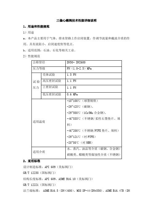
三偏心蝶阀技术性能详细说明1、用途和性能规范1)用途a、本产品主要用于气体、排水管路上作启闭装置,作调节流量和截流介质的作用。
具有流阻小,启闭速度快等优点。
b、适用范围:石油、石化等相关工业。
2)性能规范2设计制造标准:API 609(美标阀门)GB/T 12238(国标阀门)结构长度标准:API 609、ASME B16.10(美标阀门)GB/T 12221(国标阀门)法兰端标准: ASME B16.5(DN≤600)、MSS SP-44(DN=550)、ASME B16.47B(DN≥650)(美标阀门)HG/T20592 系列A、 GB/T 9113或HG/T 20592或JB 79等(国标阀门)检验试验标准:API 598(美标阀门)GB/T 26480(国标阀门)3、三偏心蝶阀外型结构图三偏心蝶阀结构图4、结构特点1、硬密封蝶阀采用三偏心硬密封结构,阀座与蝶板几乎无磨损,具有越关越紧的密封功能。
2、密封圈选用不锈钢制作,具有金属硬密封和弹性密封的双重优点,无论在低温和高温的情况下,均具有优良的密封性能,具有耐腐蚀,使用寿命长等特点。
3、蝶板密封面采用堆焊钴基硬质合金,密封面耐磨损,使用寿命长。
4、大规格蝶板采用绗架结构,强度高,过流面积大,流阻小。
5、根据用户需求,硬密封蝶阀可以设计成具有双向密封功能,安装时不受介质流向的限制,也不受空间位置的影响,可在任何方向安装。
6、驱动装置可以多工位(旋转90°或180°)安装,便于用户使用。
5、装运和储存1、运输前的准备阀门端部通道和阀门外露表面是关键的部位,应采取下列措施:(a)阀门内部应清除滞留水垢,保持阀门内腔清洁、干燥。
(b)阀门外露机加工面应涂防锈油。
(c)阀门端部应有防止法兰面等机械损伤的措施。
(d)阀门启闭件应处于关闭状态。
2、搬运搬运阀门时应适当加以注意,阀门决不能抛扔或跌落,特别是手轮和阀杆不应作大型阀门的起吊或悬挂点。
克兰克里莫巴克品牌蝴蝶阀 双偏心和三偏心阀说明书
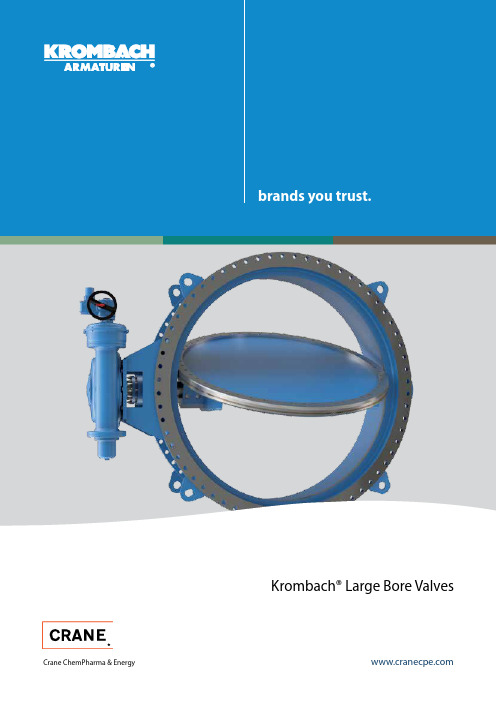
Krombach® Large Bore ValvesCrane ChemPharma & Energy2Crane ChemPharma & EnergyBacked by Crane’s 160-year tradition of engineering excellence, Krombach® brand butterfly valves from Crane ChemPharma & Energy deliver superior solutions to a range of industrial applications. Available in both Double Offset (DOV) and Triple Offset (TOV) designs, Krombach’s vast experience in the power and water markets ensures exceptional quality and reliable solutions in the industry’s most demanding applications.Applications that require "bubble-tight" shutoff demand the superior sealing capabilities of Triple Offset butterfly valves. While traditionalbutterfly valves can likewise suffer in volatile chemical applications and are prone to clogs in particulate media, Triple Offset valve technology delivers superior performance and protection in the industry’s most demanding environments.What is a DOV?To allow for easy seat displacement, the valve is designed with a double offset (DOV= double offset valves). The shaft is offset from the centerline of the bore (first offset), and the centerline of the disc seat and body seal (second offset). Together, the offsets create an eccentric disc movement that lifts the seat out of the seal,resulting in friction during the first 10 degrees of opening and final 10 degrees of closing.Figure 3: Double-offset butterfly valve designFigure 7: Details of the geometric sealing design. Both compo-nents are machined into an offset conical profile, resulting in a right-angle cone.Figure 6: Third off-set “right-angled cone” seat designWhat is a TOV?The valve is designed with a triple offset (TOV= triple offset valves), where the third offset is the geometric design of the disc and the seat. Both components are machined into an offset conical profile, resulting in a right-angle cone. This ensures nearly friction-free operation of the 90° movement. The contact is made in only the final point of closure, acting as a mechanical travel stop. This prohibits over-travel of the disc.3Figure 4: First offset of the shaft to the centerline of the boreFigure 5: Second offset from the centerline of the disc seat and body seal12Figure 1: First offset of the shaft to the centerline of the boreFigure 2: Second offset from the centerline of the disc seat and body seal123Crane ChemPharma & EnergyKrombach DOV Krombach TOVG MCooling Water Boiler Feed Water PumpLP Turbine TurbineSteam: High/Intermediate pressure up to 400 psig @ max 1100°F Water: Low/Intermediate pressure up to 2000 psig @ maxApplicationsHEAT RECOVERY STEAM GENERATORCOMBINED CYCLEKrombach DOV Krombach TOV4Crane ChemPharma & EnergySingle- or b idirectional locking device secures disc position whilemaintenance is performed, facilitating in-line repair and enhancing safety.Design FeaturesTop mounting flange in accordance with ISO 5211is suitable for manual gear, electric,hydraulic and pneumatic actuation.Welded design increases versatility to meet several design standards in face to face dimensions, pressure ratings and pipe connection.• DIN• ANSI/ASME • AWWA5Crane ChemPharma & EnergyDifferent materials for sealing element available inEPDM-10°C to 200°C / 14°F to 390°F NBR-15°C to 100°C / 5°F to 212°F FKM-10°C to 200°C / 14°F to 390°FDesign FeaturesSafety lock for locking device optional available prevents accidental open-ingThe sealing element is carried by disc and the seat retainer ring is replaceable. This ensures easier maintenance and facilitates the adjust ability of the sealingelement.(The application might changethe temperature range)6Crane ChemPharma & EnergyFeatures and BenefitsMaterials❶Key FeaturesRub b er-lined sealing element Rubber-lined sealing on the disc facilitates maintenance, reduces friction between seat and seal in the first 10 degrees on opening and last 10 degrees of closing. This extends the service life.Available in single or bidirectionalconfigurations, the locking device secures disc position while maintenance is performed on the disc, facilitating in-line repair and enhancing safety.Rubber lined options deliver superiorperformance and protect sensitive valve components in corrosive applications.* other materials upon requestDisc in open positionDisc in half-open position Disc in closed positionDisc Operation7Crane ChemPharma & EnergySizesConnections• Flanged design according to DIN EN 1092-1, ASME B 16.47-RF, and AWWA C207• Buttwelded Ends*Face to Face Dimensions• Face to face dimensions according to DIN EN 558-1 R14, ASME 16.10, and AWWA C504Temperature• Liner EPDM-20°C to 120°C / -4°F to 250°F*• Liner NBR-15°C to 100°C / 5°F to 212°F*• Liner FKM-10°C to 200°C / 14°F to 390°F*Certifications• Design according to UVV-O 2Applications• Cooling water cycle isolation (Power industry) • Drinking water pump stations • Desalination plantsOptions• Electric heat tracing/jacket to prevent freezing in low-temperature applications• Stem extension with stuffing box possible upon request• Hard-rubber lined version available for seawater applications (specification of rubber lining depending on application)* other sizes available on requestTechnical Specifications* either Krombach design or customer requirements* the application might reduce the applicable temperature range8Crane ChemPharma & Energy Design FeaturesNo contact between sealing elements during 90° operation reduces wear and maintenance over a long life time.Torque-generated sealingUnlike position-seated ball valves, resilient seated butterfly valves and plug valves, the Krombach TOV is seated with the application of torque. The right-angle conical design enables sealing by contact, rather than through the friction generated by the elastic deformation of the seat.ISO 5211actuation.9Crane ChemPharma & EnergyDesign FeaturesWelded design offers the versatility to meet several design standards regarding face-to-face dimensions, pressure rating and pipe connection.• DIN• ANSI/ASME • AWWAThe sealing element is carried by disc and the seat retainer ring is replaceable. This ensures easier maintenance and facilitates t he a djustability of the sealing element.10Crane ChemPharma & EnergyFeatures and BenefitsMaterials❶Key FeaturesA wider seat angle (24°) and self-releasingmechanism prevent excessive rubbing, sticking or galling of the laminated portion of the disc, enabling longer service life and lower operating torque with smaller actuators.Metallic seat offers superior leakprotection in volatile high-pressure and temperature applications and aremanufactured in accordance with ISO5208 and EN 12266-2.Self-centering disc design ensureshigh-integrity in-line sealing even whenthe seal is offset, and delivers exceptional performance in high- temperature cycling.* other materials upon request11Crane ChemPharma & EnergySizesConnections• Flanged design according to DIN EN 1092-1, ASME B 16.47-RF, and AWWA C207• Buttwelded Ends*Face to Face Dimensions• Face to face dimensions according to DIN EN 558-1, ASME 16.10, and AWWA C504Temperature• -20°C to 550°C / -4°F to 1100°F*Certifications• Design according to UVV-O 2Applications• Compressor blow-off (quick opening) • Steam / combustion turbines• Steam / combustion lines on an air condenserOptions• Electric heat tracing/jacket to prevent freezing in low-temperature applications• Stem extension with stuffing box possible upon request• Single or bidirectional locking device available* other sizes available on requestTechnical Specifications* the application might reduce the applicable temperature range* either Krombach design or customer requirementsC P E -K R O M B A C H -L A R G E B O R E -B U -E N -A 4-2014_09_08Friedrich Krombach GmbH ArmaturenwerkeMarburger Str. 364 57223 Kreuztal, Germany Tel: +49 2732 520 00Fax: +49 2732 520 100Crane ChemPharma & EnergyCrane Co. and its subsidiaries cannot accept responsibility for possible errors in catalogues, brochures, other printed materials, and website information. Crane Co. reserves the right to alter its products without notice, including products already on order provided that such alteration can be made without changes being necessary in specifications already agreed. All trademarks in this material are property of the Crane Co. or its subsidiaries. The Crane and Crane brands logotype, in alphabetical order, (ALOYCO®, CENTER LINE®, COMPAC-NOZ®, CRANE®, DEPA®, DUO-CHEK®, ELRO®, FLOWSEAL®, JENKINS®, KROMBACH®, NOZ-CHEK®, PACIFIC VALVES®, RESISTOFLEX®, REVO®, SAUNDERS®, STOCKHAM®, TRIANGLE®, UNI-CHEK®, WTA®, and XOMOX®) are registered trademarks of Crane Co. All rights reserved.© Crane ChemPharma & Energybrands you trust.。
三偏心蝶阀

三偏心蝶阀说明书一、特点及用途:该阀门采用三偏心金属密封结构,在室温或高温下均具有良好的密封性能,与同规格闸阀或截止阀相比,体积小,重量轻,启闭灵活,使用寿命长,广泛适用于冶金、轻工、电力、石油化工、煤气水道等领域,使用安全可靠,该阀门是现代化企业最理想的选择。
二、标准规范:D343H-16C/25 D373H-16C/25按照下列标准执行1.设计制造与检验按照JB/T8527-1997规定。
2.法兰连接尺寸按GB9113.3-88;GB9113.4-88的规定。
3.结构长度按GB12221-89的规定。
4.阀门压力试验按GB/T13927-92的规定。
D343H-150Lb D373H-150Lb 按照下列标准执行1.设计制造与检验按照API 609规定。
2.法兰连接尺寸按API 609的规定。
3.结构长度按API 609的规定。
4.阀门压力试验按API 598的规定。
三、主要性能规范:公称压力PN GB1048ANSI 150LBMPa1.0 1.62.5 2.2 强度密封试验压力PS 1.5 2.43.8 3.0 高压密封试验压力PS 1.11.762.82.2低压气密封试验压力PS0.6材质 WCB 适用温度℃ -29~425 适用介质水、蒸气、油品四、主要零件材料 零件名称 阀体、蝶板、支架压板 阀杆 密封圈 D343H-16C/25 D373H-16C/25WCB252Cr131Cr18Ni9/XB450D343H-150LbWCB 25 2Cr13 1Cr18Ni9/XB450 D373H-150Lb五、三偏心金属密封蝶阀的密封原理:图1为本公司生产的典型三偏心金属密封蝶阀密封副结构简图。
(1)结构特征。
蝶板回转中心(即阀门轴中心)与蝶板密封面形成一个尺寸A偏置,并与阀体中心线形成一个B偏置;阀体密封面中心线与阀座中心线(即阀体中心线)形成一个角度为β的角位置。
(2)密封原理。
三偏心蝶阀使用说明书
1.2 特点: a. 采用国内最先进的三偏心金属密封结构,具有密封自动补偿作用,密封可靠
性好。 b. 启闭蝶板时密封面脱开角大,密封面磨损小,摩擦扭矩小。 c. 结构设计合理,使用寿命长,驱动力矩小,操作灵活,开关迅速。 d. 体积小、重量轻,安装方便。 e. 适用介质范围广:水、海水、油品、空气、煤气、蒸汽等介质均可使用。
手、电动三偏心金属密封蝶阀 阀门有限公司
第4页 共5页
D343P-6C,DN600,D943P-6C,DN1200
使用说明书
调整片予以解决,若密封圈有损坏,可取下密封圈压板更换密封圈,当轴封处泄 漏时,取下填料压盖更换填料即可。
6. 注意事项
6.1 开箱时应注意不要损坏箱内零部件,应按装箱单核对配套件是否齐全。 6.2 安装前应仔细核对使用工况与本阀的性能是否相符,确保相符后方可进行安 装。 6.3 轻吊轻放,避免损坏阀门内部零件。 6.4 进行管路强度试压时,必须打开蝶板。 6.5 户外安装使用时,电动装置需要防雨设施。 6.6 本蝶阀在-5℃以下的室外环境安装使用时,需要附加防寒保暖设施。
手、电动三偏心金属密封蝶阀 阀门有限0,D943P-6C,DN1200
使用说明书
3.1.2 手动蝶阀主要由:阀体、蝶板、阀轴、端盖、填料、填料压盖、蜗轮传动 装置等部件组成。如图 2。
15 14
13 12
11
10 9
8
7 6 5 4
3 2 1
图 2.D343P-6C,DN600 手动蝶阀外形尺寸图 1.端盖 2.阀体 3.轴套 4.下阀轴 5.蝶版 6.密封圈 7.密封圈压板 8.连接销 9.上阀轴 10.填料 11.填料压盖 12.支座 13.销 14.传动装置 15.手轮驱动装置
气动蝶阀说明书
气动硬密封三偏心蝶阀使用说明书1.产品概述气动蝶阀具有优良的切断性能和调节性能,其阀板与密封组件采用了金属U型弹性阀座和三偏心阀板结构。
阀板形状为椭圆形圆锥体。
当阀门打开时,椭圆形圆锥体密封面先脱离U形弹性阀座,然后再旋转,这样可降低摩擦阻力和磨损。
当阀门关闭时阀板旋转,在偏心轴的作用下阀板向弹性阀座进行自动调整中心,对阀座压紧,使阀座变形,直到阀座与阀板椭圆形圆锥密封面紧密吻合,从而保证密封要求,减少了阀门开启所需的扭矩,延长了阀门的使用寿命。
该两大系列产品具有调节及快速切断、调节等三种功能,是经济实用型自动控制阀,特别适用于石化、电力、冶金、轻工等工业部门使用。
2.主要技术参数2.1 阀体型式:扁平偏置铸造或锻造阀体公称通经:DN50—800mm公称压力:PN1.6、2.5、4.0MPa连接型式:无法兰对夹式RF型或法兰连接RF型材料:WCB CF8 CF8M填料:石棉浸四氟聚四氟乙烯柔性石墨2.2 阀内组件阀芯型式:偏心旋转式阀板材质:WCB镀硬铬、CF8、CF8M阀座材料:软密封(R型):聚四氟乙烯温度范围:-40—+180℃对位聚苯温度范围:-40—+300℃硬密封(Y型):304或316,温度范围:-40—+425℃阀轴材料:17-4PH 3163.主要技术性能指标表18.主要外形尺寸4.产品结构及工作原理气动蝶阀主要由气动活塞执行机构及蝶阀阀体部件两大 部分组成。
也可配装手操机构或相关附件等组成。
4.1气动活塞执行机构 4.1.1产品结构气动活塞执行机构主要由气缸缸体、活塞、端盖、齿轮轴、 密封圈及弹簧等组成。
分双作用(H)型和单作用(T)型两种。
4.1.2工作原理(一)双作用型工作原理(标准转向)俯视(二)单作用型(弹簧复位)工作原理(标准转向)俯视标准旋转方向是:顺时针关,逆时针开※对于关闭压差较大,需要配装拨叉式较大输出力气缸执行机构时,可配装6500RA 型气动活塞执行机构。
三偏心蝶阀使用说明书
手、电动三偏心金属密封蝶阀 阀门有限公司
第2页 共5页
D343P-6C,DN600,D943P-6C,DN1200
使用说明书
3.1.2 手动蝶阀主要由:阀体、蝶板、阀轴、端盖、填料、填料压盖、蜗轮传动 装置等部件组成。如图 2。
15 14
13 12
11
10 9
8
7 6 5 4
3 2 1
图 2.D343P-6C,DN600 手动蝶阀外形尺寸图 1.端盖 2.阀体 3.轴套 4.下阀轴 5.蝶版 6.密封圈 7.密封圈压板 8.连接销 9.上阀轴 10.填料 11.填料压盖 12.支座 13.销 14.传动装置 15.手轮驱动装置
使用说明书
2. 型号表示方法 D94 3 P 6 C
主体件材料代号:C-碳素钢
公称压力:以MPa表示的公称压力的十倍数值
密封材料:H-硬质合金;P-奥氏体不锈钢;R-超低炭不锈钢
结构形式:1.垂直板式2.双偏心3.三偏心 连接形式:4-法兰连接;6-对焊连接;7-对夹连接 驱动方式:无-手柄驱动;3-蜗轮蜗杆;6-气动;7-液动;9-电动
阀门类别:D-蝶阀
3. 主要结构、工作原理、外形尺寸及连接尺寸
主要结构 3.1.1 电动蝶阀主要由:阀体、蝶板、阀轴、端盖、填料、填料压盖、传动装置、 电动装置等部件组成。如图 1。
15 14
13 12
11
10 9
8
7 6 5 4
3 2 1
图 1.D943P-6C,DN1200 电动蝶阀外形尺寸图 1. 端盖 2.阀体 3.轴套 4.下阀轴 5.蝶版 6.密封圈 7.密封圈压板 8.连接销 9.上阀轴 10.填料 11.填料压盖 12.支座 13.销 14.传动装置 15.电动装置
- 1、下载文档前请自行甄别文档内容的完整性,平台不提供额外的编辑、内容补充、找答案等附加服务。
- 2、"仅部分预览"的文档,不可在线预览部分如存在完整性等问题,可反馈申请退款(可完整预览的文档不适用该条件!)。
- 3、如文档侵犯您的权益,请联系客服反馈,我们会尽快为您处理(人工客服工作时间:9:00-18:30)。
企业简介
上海凯工阀门有限公司地处上海嘉定工业园区,公司占地面积439600平方米,是一家专业设计、制造和销售各种阀门的大型股份制企业。
公司拥有专业的阀门设计、制造工程技术人员,拥有各类机加工设备和试验装置。
公司已通过挪威船级社DNV ISO9001:2000质量管理体系认证、英国UKAS ISO14001环境管理体系认证和美国石油协会API 6D 标准认证。
公司是中国通用机械阀门行业协会的会员单位,中石油、中海油、中石化的战略合作企业,化工装备定点生产企业,是中国城市燃气协会会员单位。
公司的产品有闸阀、截止阀、止回阀、蝶阀、球阀及高温炼化、炼油、炼焦、长输管线、油田、电站高压等阀门。
产品的公称压力从PN1.0~80MPa ,公称通径DN15~2500mm ;温度从-196℃~600℃。
产品采用的标准有GB 、JB 、API 、ANSI 、JIS 、BS 、DIN 等。
三偏心金属密封蝶阀系列是我公司主要产品,大量使用在冶金、轻工、电力、石油化工、煤气水道等领域。
上海凯工以“发掘尖端阀门技术,竭尽全力回报用户”作为企业的经营理念,以给用户提供优质产品和满意服务为己任,不断地进行自身变革,力争成为中国阀门行业的明珠企业。
一、特点及用途:
该阀门采用三偏心金属密封结构,在室温或高温下均具有良好的密封性能,与同规格闸阀或截止阀相比,体积小,重量轻,启闭灵活,使用寿命长,广泛适用于冶金、轻工、电力、石油化工、煤气水道等领域,使用安全可靠,该阀门是现代化企业最理想的选择。
二、标准规范:
D343H-16C/25 D373H-16C/25按照下列标准执行
1.设计制造与检验按照JB/T8527-1997规定。
2.法兰连接尺寸按GB911
3.3-88;GB9113.4-88的规定。
3.结构长度按GB12221-89的规定。
4.阀门压力试验按GB/T13927-92的规定。
D343H-150Lb D373H-150Lb 按照下列标准执行
1.设计制造与检验按照API 609规定。
2.法兰连接尺寸按API 609的规定。
3.结构长度按API 609的规定。
4.阀门压力试验按API 598的规定。
五、三偏心金属密封蝶阀的密封原理:图1为本公司生产的典型三偏心金属密封蝶阀密封副结构简图。
(1)结构特征。
蝶板回转中心(即阀门轴中心)与蝶板密封面形成一个尺寸A偏置,并与阀
体中心线形成一个B偏置;阀体密封面中心线与阀座中心线(即阀体中心线)形成一个
角度为β的角位置。
(2)密封原理。
由于在双偏心密封蝶阀的基础上,将阀座中心线再与阀体中心线形成一
个β角位置,其偏置后的结果由图2的A-A剖视图可见,当三偏心密封蝶阀处于
完全开启状态时,其蝶板密封面会完全脱离阀座密封面,并且在蝶板密封面与阀体
密封面之间形成一个与双偏心密封蝶阀相同的间隙Y,而由图3可见,由于β角位
置的形成会使长、短半径转动的蝶板大、小半圆上,蝶板密封面转动轨迹的切线与
阀座密封面形成一个θ1和θ2角。
使蝶板启闭时蝶板密封面相对于阀座密封面渐出
脱离和渐入压紧,从而彻底消除了蝶板启闭时蝶阀密封副两密封之间的机械磨损和
擦伤。
该阀门从0°~90°开启时,蝶板的密封面会在开启瞬间立即脱离阀座密封面,在其90°~0°关闭时,只有在关闭的瞬间,其蝶板密封面才会接触并压紧阀座密封
面。
由图2可见,由于θ1、θ2角的形成,使蝶阀关闭时,其密封副两密封面之间
的密封比压可以由常规蝶阀的阀座弹性产生改为外加于阀门轴的驱动转矩产生,不
仅消除了常规蝶阀中弹性阀座弹性材料老化、冷流、弹性失效等因素造成的密封副
两密封面之间的密封比压降低和消失,而且可以通过对外加驱动转矩的改变实现对
其密封比压的任意调整,从而使三偏心蝶阀的密封性能和使用寿命得到大大的提高。
图1 三偏心金属密封蝶阀
图3 三偏心金属密封蝶阀关闭状态图
六、阀门的主要外形尺寸、连接尺寸及重量见附图4:
图4 法兰连接三偏心金属密封蝶阀结构外形图
图5 对夹式三偏心金属密封蝶阀结构外形图
型三偏心金属密封蝶阀
上海凯工阀门有限公司
D373H-150Lb D373H-16C/25
D343H-150Lb D343H-16C/25。