货车驾驶室液压翻转机构(翻译附原文,仅供参考)
驾驶室翻转液压锁总成技术条件DFCVCJ1251-2013

Q/DFCV东风商用车有限公司技术标准化委员会发布Q/DFCVCJ 1251—2013本标准按GB/T 1.1-2009给出的规则起草。
本标准与Q/DFLCJ1251—2009相比,除编辑性修改外主要技术变化如下:――修改了规范性引用文件(第2章);――工作环境温度调整为-30℃~+80℃(3.13项)。
――液压锁栓总成的活塞顶起的最大工作压力调整为不大于1.5Mpa(3.4项)。
――总成清洁度检测方法改为按EQY-11执行(3.17项)。
――增加了液压锁锁止传感器的技术要求(3.19项)和防尘防水试验方法(4.7项)。
――修订了高低温密封性及耐压试验方法(4.1.2项)。
本标准由东风商用车有限公司东风商用车技术中心提出。
本标准由东风商用车有限公司东风商用车技术中心开发管理部归口。
本标准起草单位:东风商用车有限公司东风商用车技术中心车身开发部。
本标准主要起草人:石光勇、谭川、陈玲莉、陈海斌、魏铭、邱福铭、郭凯、王庆、于渊。
本标准代替了Q/DFLCJ 1251-2009。
本标准的历次版本发布情况为:――Q/DFLCJ 1251-2009。
1 范围本标准规定了驾驶室液压翻转系统中所采用的液压锁总成的技术条件、试验方法,检验规则及标志、包装、贮运等。
本标准适用于东风商用车有限公司采用液压锁锁止驾驶室的全系列车型。
2 规范性引用文件下列文件对于本文件的应用是必不可少的。
凡是注日期的引用文件,仅所注日期的版本适用于本文件。
凡是不注日期的引用文件,其最新版本(包括所有的修改单)适用于本文件。
GB/T 10125 人造气氛腐蚀试验盐雾试验GB7324 通用锂基润滑脂GB8410 汽车内饰材料的阻燃特性GB 4208 外壳防护等级(IP代码)Q/EQY-11 汽车零件清洁度测定方法Q/EQY-2 油漆涂层Q/EQY-3 电镀层及化学处理层Q/EQY-60 东风牌汽车备件包装、定额包装技术条件Q/EQY-63 出国备件包装要求Q/EQY-66 汽车产品防锈包装办法Q/EQY-76 东风汽车备件验收、保管、发送贮运技术条件3 技术要求3.1 驾驶室液压锁总成及零部件应按照规定程序批准的产品图纸及技术文件制造。
载重汽车驾驶室翻转机构的分析

维普资讯
Q iehesh ej i
的
可靠性较差 ,液压举升机构在使用 中故障较多,并且 由于完全
靠手动 ,翻转速度极慢 。
1 3 电动/手动 液压式机构 . 为了提高翻转速度 ,目前国外的中、重型载货汽车普遍采
用了 电动 / 手动液 压翻转机 构。 翻转机构工 作时 ,启动 电动
驾驶室采用整体半环绕式工作台,使司机对各个部件的操作触手 可及 ,不至于分散司机驾驶时的注意力。除音响系统和冷暖风系 统采用按钮和旋钮开关之外 ,其它 电气开关均采用翘板式 。喇叭 开关安置 在组 合开关左 侧的手柄上 ,门窗采用“ 一触式” 电动升 降 ,天窗采用 电动操作 ,这 些都 大大简化 了司机的操作 。 “ 数字液晶屏 +电子指针” 式组合仪表十分美观 ,而且布局科
电机转子轴上装有偏心轮电机转动带动偏心轮回转偏心轮使得柱塞作上下往复运动当偏心轮转向上方时柱塞在弹簧的作用下迅速向上移动油腔a的容积逐渐增大形成部分真空油箱中的油液就通过a1顶起钢球1进入油腔a这时泵为吸油
维普资讯
( j
… ÷ 一
c l
网田 hse Qcehi i i
可靠。
12 手动液压式机构 . 载重汽车驾驶室特别是承载质量大的驾驶室 ,采用
液压 翻转机构 ,可以使汽车 装调 和维 修更轻便 。该机构 采用一手动柱 塞泵 驱动 翻转 油缸 ,通 过其 中换 向轴 改变 油缸运动 方向,使 驾驶 室围绕前 支点翻转。为确保装调 和维修 人员的安全 ,驾驶室 的翻转油缸必 须在手动 泵作 用时 方可 运动 ;同时配 备机械安全保 险,即在需要驾驶 室下降时 ,必 须拉动棘爪使其 离开棘齿 ,翻转 缸方可 向下运动 ,驾驶室才能下降至原位。 由于 目前液压件的
汽车起重机主要部件中英文对照

汽车起重机主要部件中英对照随着越来越多的外资品牌起重机进入中国市场,汽车起重机行业的竞争也越来越激烈,用户的选择和需要接触的信息也越来越多。
用户在面对一款外国起重机产品手册时,往往束手无策。
本文将向大家介绍汽车起重机产品和各项性能的对照英文翻译,让你在面对英文版产品手册时也不再发愁。
汽车起重机整体结构()中英文对照①副臂 Boom with extension②起重臂伸缩机构 Boom telescopic③主臂 Main boom④变幅机构 Luffing⑤起升机构 Hoist⑥卷扬马达 Hoist motor⑦支腿机构 Outrigger⑧回转机构Slewing⑨底盘 Chassis⑩液压系统 Hydraulics⑪驾驶室 Driver Cab一、汽车起重机外形尺寸(Mobile Crane Dimensions)中英文对照接近角Approach angle 30离去角Departure angle 10.5最小离地间隙260(320)轴距Wheel Base 3950高度Height 3080长度Length 8440汽车地盘长度Chassis Length 7002基础臂长Base boom length 68001-支腿纵向跨距Outrigger Longitudinal span2-2-支腿横向跨距Outrigger Transverse span3-3、4-机身宽度 WidthCrane Weights 起重机总重量Gross vehicle weight (GVW) 车辆总重量 (GVW)Axle Loads 桥负荷Steering axle (axle 1) 转向桥 (桥 1)Drive axle (axle 2) 驱动桥 (桥 2)Ground Clearances 通过性参数Minimum ground clearance 最小离地间隙Ramp angle 纵向通过角Approach angle 接近角Departure angle 离去角Wheel Base 轴距Distance between axle 1 and 2 桥 1 和 2 之间的距离Wheel Track 轮距Axle 1 桥 1Axle 2 桥 2Outrigger Dimensions 支腿跨距Longitudinal span 纵向跨距Transverse span 横向跨距Outrigger Forces 支腿反力Maximum counterforce 最大支反力Overall Dimensions 外形尺寸(Length x Width x Height) (长 x 宽 x 高)技术描述Lifting Capacity 起重量Maximum rated capacity for main hook主钩额定起重量Maximum load moment最大起重力矩Boom and Components 主臂和零件Profile截面形状Number of sections节数Base boom length基本臂长度Base boom maximum lift height基本臂最大起升高度Base boom maximum working radius基本臂最大作业半径Fully extended boom length全伸臂长度Fully extended boom maximum lift height全伸臂最大起升高度Fully extended boom maximum working radius 全伸臂最大作业半径Jib 副臂Jib length副臂长度Slewing speed回转速度Winch Performance 起升机构工作速度Main hoist – 3rd layer – single rope speed 主卷扬 - 第三层 - 单绳速度Crane Boom Function Speeds 起重臂工作速度Elevation – up起臂Elevation – down落臂Full extension全伸Full retract全缩Outrigger Function Speeds 支腿工作速度Simultaneous full extension同步伸出Simultaneous full retract同步收缩Outrigger Controls 支腿操纵Dual outrigger controls – LH and RH side 支腿操纵 - 左侧和右侧Ambient working temperature作业温度Engine and Transmission 发动机和变速箱Engine发动机Emission compliance排放标准Number of cylinders缸数Aspiration进气Rated power额定功率Maximum torque最大扭矩Estimated fuel consumption per 100 km100 km 油耗Fuel type燃油类型Fuel tank capacity燃油箱容积Manual gearbox手动变速箱Hydraulics 液压装置Combined system with dual pump带有双泵的组合系统Hydraulic controls:液压控制:Mechanical, multi-lever controls机械式,多杆控制底盘基本构造1-发动机 Engine2-离合器 Cluth3-变速箱 Transmission Case4-万向节 Universal Flange5-后桥壳 Rear Axle Housing6-差速器 Differential7-半轴 Axle Shaft8-后桥 Rear Axle9-中桥 Intermediate Axle10-主减速器 Reducer11-传动轴 Drive ShaftEngineChassis and Components 底盘及其部件Axle drive system桥驱动系统Minimum turning radius最小转弯半径Maximum gradeability最大爬坡度Maximum traveling speed最高行驶速度Driver Cab 驾驶室Dong Feng truck cab东风卡车驾驶室Adjustable driver seat调式司机座椅可Fitted with heater加热器Operator Cab 操纵室Adjustable seat可调式座椅Ergonomically placed switches and gauges 开关和仪表的布置符合人机工程学Recirculation fan循环风扇主要参数表最大起重量 Max.Rated Lifting Capacity最大起升高度 Max.Lifting Height主臂Main Boom副臂JibM最大起升力矩ax.Hoisting Moment最大起升速度(单绳) Max.Lifting Rope Speed回转速度Slewing Speed外形尺寸Qutline Dimension整机重量Weight Data底盘号Chassis Model发动机型号Diesel Model发动机功率Max.Power of engline最大扭矩Max.Torque of engine最小转弯半径Min.Turing Radius最大爬坡度Max.Gradeabilitg最高行驶速度Max.Trave Ling Speed接近角Approach Angle离去角Angle of Departure支腿距离(纵向×横向) Qutriggers Di Stance。
驾驶室翻转液压系统设计说明
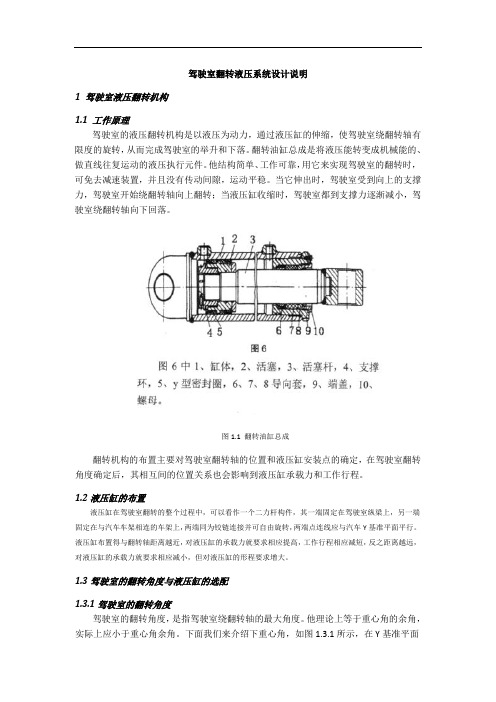
驾驶室翻转液压系统设计说明1 驾驶室液压翻转机构1.1 工作原理驾驶室的液压翻转机构是以液压为动力,通过液压缸的伸缩,使驾驶室绕翻转轴有限度的旋转,从而完成驾驶室的举升和下落。
翻转油缸总成是将液压能转变成机械能的、做直线往复运动的液压执行元件。
他结构简单、工作可靠,用它来实现驾驶室的翻转时,可免去减速装置,并且没有传动间隙,运动平稳。
当它伸出时,驾驶室受到向上的支撑力,驾驶室开始绕翻转轴向上翻转;当液压缸收缩时,驾驶室都到支撑力逐渐减小,驾驶室绕翻转轴向下回落。
图1.1 翻转油缸总成翻转机构的布置主要对驾驶室翻转轴的位置和液压缸安装点的确定,在驾驶室翻转角度确定后,其相互间的位置关系也会影响到液压缸承载力和工作行程。
1.2液压缸的布置液压缸在驾驶室翻转的整个过程中,可以看作一个二力杆构件,其一端固定在驾驶室纵梁上,另一端固定在与汽车车架相连的车架上,两端同为铰链连接并可自由旋转,两端点连线应与汽车Y基准平面平行。
液压缸布置得与翻转轴距离越近,对液压缸的承载力就要求相应提高,工作行程相应减短,反之距离越远,对液压缸的承载力就要求相应减小,但对液压缸的形程要求增大。
1.3驾驶室的翻转角度与液压缸的选配1.3.1驾驶室的翻转角度驾驶室的翻转角度,是指驾驶室绕翻转轴的最大角度。
他理论上等于重心角的余角,实际上应小于重心角余角。
下面我们来介绍下重心角,如图1.3.1所示,在Y基准平面上,从翻转轴中心到驾驶室重心的连线与水平线的夹角即为重心角,可按arcthH/L求得重心角。
图1.3.1驾驶室翻转角极限状态下,驾驶室的翻转角度与重心角互余,此时驾驶室的重心在翻转轴线上,驾驶室的全部质量都由驾驶室前支撑点支撑,液压缸的支撑力为零,驾驶室翻转轴上的剪力和挤压力也达到最大值。
极限状态是不安全的,此时一旦驾驶室在其他外力作用下向前翻转,驾驶室的重心将越过翻转轴重心的垂线,对液压缸产生“拉力”,给车辆和人员将带来危险。
载重汽车驾驶室翻转机构的分析

载重汽车驾驶室翻转机构的分析
王欣;宋正和;秦松祥
【期刊名称】《重型汽车》
【年(卷),期】2007(000)002
【摘要】近几年来,载重汽车行业的竞争越来越激烈,汽车部件也不断地更新换代,更高质量、更安全、更舒适自勺产品不断推出,载重汽车的主要部件驾驶室也不例外。
目前,我国载重汽车驾驶室的设计均趋于平头化,此型设计,发动机必须置于驾驶室的下方。
为了便于发动机的检查、保养、维修,要求驾驶室向前翻转。
【总页数】2页(P16-17)
【作者】王欣;宋正和;秦松祥
【作者单位】无
【正文语种】中文
【中图分类】U4
【相关文献】
1.某中型载货车驾驶室翻转机构轻便性分析与试验
2.基于Matlab/Simulink在驾驶室液压翻转机构设计中的仿真分析研究
3.一种重卡驾驶室翻转机构疲劳试验系统建设及试验方法的研究
4.某轻卡驾驶室翻转机构的设计与分析
5.重卡驾驶室液压翻转机构翻转缸悬置状态仿真分析
因版权原因,仅展示原文概要,查看原文内容请购买。
驾驶室中英文

平头驾驶室 forward control cab 长头驾驶室 conventional cab双排座驾驶室 crew cab带卧铺驾驶室 sleeper cab翻转式驾驶室 tilt cab驾驶室本体 main body驾驶室覆盖件 cover panel内饰件 interior trimming parts 外饰件 exterrior trimming parts 附件 equipment挡板 guard板件 panel衬板 patch连接板 connecting panel盖 lid罩 cover支架 support(bracket . brace) 骨架 member(rail beam)筋 rib密封条 weatherstrip衬垫 pad(packing .gasket)装饰件 trimming(finisher. molding) 驾驶室悬置 cab mounting地板 floor pan(floor panel)纵梁 side rail(side member)横梁 cross rail轮罩 wheel housing挡泥板 mudguard发动机罩 engine cover风窗玻璃 windshield glass侧窗玻璃 side window glass门窗玻璃 door window glass后窗玻璃 rear window glass仪表板 instrument panel(fascia)杂物箱 glove box翻转机构 tilting mechanical hardware 门铰链 hinge玻璃升降器 window regulator后视镜 rear view mirror刮水器 wiper风窗洗涤器 washer遮阳板 sun visor空调装置 air conditioner(air conditioning equipment)暖风装置 heater冷风装置 cooler通风装置 ventilator除霜装置 defrostor(demister)肘靠 arm rest扶手 handrail(hand grill. banisters)拉手 assist grip(handle)安全带 seat belt标牌 label汽车商标 emblem(mark. insignia)货箱 cargo body(conventional type rear body. high deck body) 厢式货箱 van body低台货箱 low deck body高栏板货箱 high gate cargo body梁 sill纵梁 main sill(main bolster.side sill)纵梁垫木 wood filler block(main sill liner)横梁 cross sill (bolster)货箱栏板 gate边板 side gate栏板铰链 gate hinge栏板立柱 support post缓冲垫 cushion rubber (bumper)反光器 reflector车辆 vehicle底盘 chassis货车 motor truck微型货车 mini truck轻型货车 light truck中型货车 medium truck重型货车 heavy truck越野汽车 off-road truck自卸汽车 dump truck专用汽车 special purpose vehicle轿车 passenger car底盘干质量 chassis dry mass底盘整备质量 chassis kerb mass整车整备质量 compete vehicle kerb mass最大总质量 maximum total mass厂定最大总质量 maximum manufacture's total mass允许最大总质量 maximum authorized total mass最大装载质量 maximum laden mass厂定最大装载质量 maximum manufacture's laden mass 最大轴载质量 maximum axle laden mass允许最大轴载质量 maximum authorized axle laden mass 比功率 power/mass ratio比扭矩 torque/maximum total mass ratio车长 vehicle length汽车长 motor vehicle length车宽 vehicle width车高 vehicle height轴距 wheel base轮距 track前悬 front overhang后悬 rear overhang最小离地间隙 ground clearance纵向通过角 ramp angle接近角 approach angle离去角 departure angle车架高度 height of chassis above ground转弯直径 turning circles diameters转弯通道圆 turning clearance circles有效载荷 payload 载质量 capacity 轴荷 axle load 容量 capacity。
中文翻译-自卸车液压伺服系统设计思路及公式
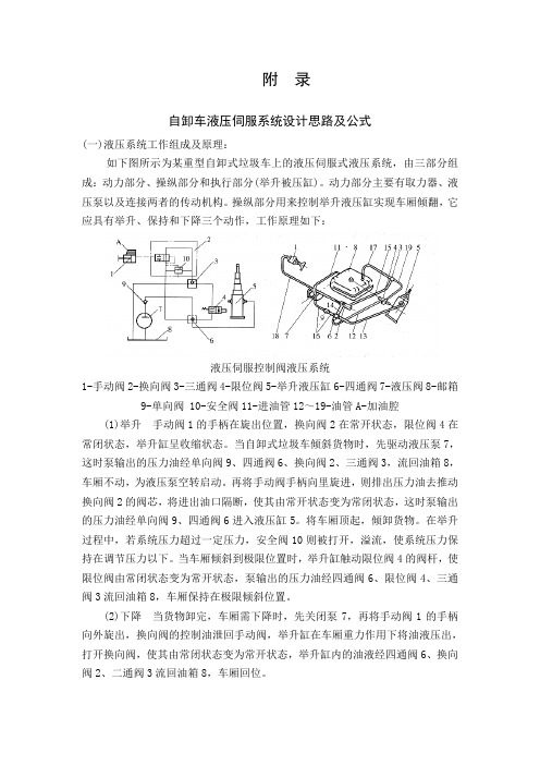
附录自卸车液压伺服系统设计思路及公式(一)液压系统工作组成及原理:如下图所示为某重型自卸式垃圾车上的液压伺服式液压系统,由三部分组成:动力部分、操纵部分和执行部分(举升被压缸)。
动力部分主要有取力器、液压泵以及连接两者的传动机构。
操纵部分用来控制举升液压缸实现车厢倾翻,它应具有举升、保持和下降三个动作,工作原理如下:液压伺服控制阀液压系统1-手动阀2-换向阀3-三通阀4-限位阀5-举升液压缸6-四通阀7-液压阀8-邮箱9-单向阀 10-安全阀11-进油管12~19-油管A-加油腔(1)举升手动阀1的手柄在旋出位置,换向阀2在常开状态,限位阀4在常闭状态,举升缸呈收缩状态。
当自卸式垃圾车倾斜货物时,先驱动液压泵7,这时泵输出的压力油经单向阀9、四通阀6、换向阀2、三通阀3,流回油箱8,车厢不动,为液压泵空转启动。
再将手动阀手柄向里旋进,则排出压力油去推动换向阀2的阀芯,将进出油口隔断,使其由常开状态变为常闭状态,这时泵输出的压力油经单向阀9、四通阀6进入液压缸5。
将车厢顶起,倾卸货物。
在举升过程中,若系统压力超过一定压力,安全阀10则被打开,溢流,使系统压力保持在调节压力以下。
当车厢倾斜到极限位置时,举升缸触动限位阀4的阀杆,使限位阀由常闭状态变为常开状态,泵输出的压力油经四通阀6、限位阀4、三通阀3流回油箱8,车厢保持在极限倾斜位置。
(2)下降当货物卸完,车厢需下降时,先关闭泵7,再将手动阀1的手柄向外旋出,换向阀的控制油泄回手动阀,举升缸在车厢重力作用下将油液压出,打开换向阀,使其由常闭状态变为常开状态,举升缸内的油液经四通阀6、换向阀2、二通阀3流回油箱8,车厢回位。
(3)保持若需将车厢举升至某一位置,只要使手动阀l 的手柄仍在旋进位置,停止泵上作,车厢即可保持在任一位置。
(二)操纵换向阀的方式可分为手动机械杠杆式、手动液压伺服式和气动操纵式三种。
机械操纵式的可靠性好,通用性强,维修方便。
但它的杆件较多,布置复杂,对于可翻转式驾驶室不宜采用这种操纵方式。
重卡驾驶室液压翻转机构翻转缸悬置状态仿真分析

重卡驾驶室液压翻转机构翻转缸悬置状态仿真分析作者:张家昌肖志权陈玲莉张明明庹明伟来源:《汽车科技》2021年第01期摘要:针对某重卡驾驶室液压翻转机构出现的泄漏等问题,对其翻转缸在悬置状态进行了基于AMESim的建模与仿真。
考虑翻转缸缩回至活塞处于缸筒扩孔区,且活塞杆随驾驶室一起做微幅振动的状态,分析了振动频率、幅值、等效缝隙值对于翻转缸两腔压力的影响,及振动过程中两腔的流量变化。
分析结果显示,悬置状态翻转缸会产生缸内负压,造成气穴乃至气蚀现象,其程度主要与翻转缸的振动频率、幅值和等效缝隙值有关,甚至是翻转缸泄漏的原因之一。
关键词:液压翻转机构;翻转缸;AMESim;气穴现象中图分类号:463.81+5 文献标识码:A 文章编号:1005-2550(2021)01-0025-06Abstract: Aiming at the leakage of a heavy truck cab hydraulic overturning mechanism, a model and simulation based on AMESim is carried out on the overturning cylinder in the suspended state. Considering that the cylinder retracts to the piston in the cylinder reaming area and the piston rod vibrates slightly with the cab, the influences of vibration frequency, amplitude and equivalent gap value on the pressure and flow of the two Chambers of the cylinder are analyzed. The analysis results show that the overturning cylinder in the suspension state generates negative pressure in both chambers of the cylinder, resulting in cavitation or even cavitation erosion under impact pressure,the degree of which is mainly related to the vibration frequency, amplitude and equivalent gap value of the overturning cylinder. This may be one of the reasons of the leakage of the overturning cylinder.Key Words: Hydraulic Overturning Mechanism; Overturning Cylinder; Amesim; Cavitation1 引言驾驶室液压翻转机构因其承载翻转力大、工作平稳、安全可靠而越来越多地应用于商用车、自卸车、中、重型载货车等多种车型。
- 1、下载文档前请自行甄别文档内容的完整性,平台不提供额外的编辑、内容补充、找答案等附加服务。
- 2、"仅部分预览"的文档,不可在线预览部分如存在完整性等问题,可反馈申请退款(可完整预览的文档不适用该条件!)。
- 3、如文档侵犯您的权益,请联系客服反馈,我们会尽快为您处理(人工客服工作时间:9:00-18:30)。
Title:Truck cab hydraulic tilting mechanismUnited States Patent 4440252Abstract:A hydraulic tilting mechanism for a driver's cab of a vehicle, with the mechanism including a double-acting working cylinder having accommodated therein a displaceable piston. Ducts or lines are provided for connecting the working cylinder with a supply tank or source of hydraulic fluid, with a pump being arranged in one of the ducts or lines and a joint control valve for controlling a movement of the piston being arranged in the ducts or lines.A closable duct by-passes the working cylinder and branches off from a three-way valve having two switch positions. The three-way valve is located in the duct or line leading to a first cylinder space which causes a tilting of the driver's cab. The three-way valve is adapted to be electromagnetically switched by way of a key. The closable duct or by-pass line discharges into a connecting duct or line arranged between the control valve and a second cylinder space which is adapted to cause a return of the driver's cab. A non-return or check valve is disposed between the three-way valve and the connecting duct into which the by-pass duct or line discharges. In one position of the three-way valve, the duct or line to the first cylinder space is opened and the by-pass duct or line is blocked and, in a second position, the duct or line to the first cylinder space is blocked and the by-pass duct or line is shut so that by means of the by-pass line or duct the hydraulic fluid is fed by the pump back to the storage tank.Inventors:Steinecke, Rudolf (Weinstadt, DE)Hensche, Karl-heinz (Leutenbach, DE)Application Number:06/322209Publication Date:04/03/1984Filing Date:11/17/1981Export Citation:Click for automatic bibliography generationAssignee:Daimler-Benz AG (DE)Primary Class:180/89.15Other Classes:91/445International Classes:B62D33/07; B62D33/06; (IPC1-7): B62D27/00Field of Search:180/89.14, 180/89.15, 91/445, 91/448View Patent Images:Download PDF 4440252 PDF helpUS Patent References:3945299 Linear positioning apparatus March, 1976 Fritz et al. 91/4453801151 DOUBLE-ACTING LIFT CYLINDERWITH INTEGRAL VELOCITY FUSESApril, 1974Reynolds etal.180/89.153792747 PRESSURE-COMPENSATED HANDPUMPFebruary,1974Knutson 180/89.153270625 Fluid motor and pressure responsivevalveSeptember,1966Huntingtonet al.91/4483033001 Hydraulic system for cranes and the like May, 1962 Russell et al. 91/445 2825306 Servomotor control system March, 1958 Buri 91/445Foreign References:SU506536 May, 1976 180/89.15Primary Examiner:Peters Jr., Joseph F.Assistant Examiner:Weaver, RossAttorney, Agent or Firm:Craig & BurnsClaims:We claim:1. A hydraulic tilting mechanism for a cab of a vehicle, the mechanism including double-acting working cylinder means arranged between the cab and frame of a vehicle, piston means displaceably mounted in the cylinder means, means for connecting the working cylinder means with a source of hydraulic fluid so as to enable displacement of the piston means in the working cylinder means by the hydraulic fluid, means for preventing unauthorized operation of the tilting mechanism including by-pass line means for by-passing the working cylinder means, valve means for selectively controlling a flow of the hydraulic fluid into the by-pass line means, manually operable switch means for controlling a positioning of the valve means for selectively controlling a flow of the hydraulic fluid into the by-pass line means, and check valve means for allowing unidirectional flow of the hydraulic fluid in the by-pass line means.2. A hydraulic tilting mechanism according to claim 1, wherein the working cylinder means includes a first cylinder space means for causing a tilting of the cab and a second cylinder space means for causing a return of the cab from a tilted to a normal position, the means for connecting the working cylinder means with a source of hydraulic fluid includes a first hydraulic line means for connecting the first cylinder space means with the source of hydraulic fluid, and a second hydraulic line means for connecting the second cylinder space means with the source of hydraulic fluid, suitable valve means arranged in the first and second hydraulic line means for controlling a flow of hydraulic fluid to and from the source of hydraulic fluid so as to control a positioning of the piston means, the valve means for selectively controlling the flow of hydraulic fluid into the by-pass line means is a valve disposed in one of said first and second hydraulic line means.3. A hydraulic tilting mechanism according to claim 2, wherein the by-pass line means branches off said valve and is connected with the other of said first and second hydraulic line means at a position between the switchable valve means and the working cylinder means.4. A hydraulic tilting mechanism according to claim 3, wherein the valve is an electromagnetic three-way two position valve means having a first position for permitting a connection between the source of hydraulic fluid and the working cylinder means and a blocking of the by-pass means, and a second position blocking a flow of hydraulic fluid to the working cylinder means and opening the by-pass line means whereby hydraulic fluid may be fed back to the source of hydraulic fluid.5. A hydraulic tilting mechanism according to claim 3, wherein said check valve means opens in a direction of the other of said first and second hydraulic line means.6. A hydraulic tilting mechanism according to claims 1, 2, 3, 4, or 5, wherein the manually operable switch means is a key-operated switch.7. A hydraulic tilting mechanism according to claim 6, wherein means are connected to an engine of the vehicle for preventing an unauthorized operation thereof, and means are provided for connecting the manually operableswitch means with the unauthorized operation preventing means so as to enable the means for selectively controlling the flow of hydraulic fluid into the by-pass line means and the unauthorized operation preventing means to be operated by a joint key-operated switch.8. A hydraulic tilting mechanism according to claim 7, wherein the piston means includes a piston rod having one end thereof pivotably connected to the cab of the vehicle, and a bottom portion of the working cylinder means is pivotably connected to the frame of the vehicle.9. A hydraulic tilting mechanism according to claim 7, wherein the piston means includes a piston rod having one end thereof pivotably connected to the frame of the vehicle, and a portion of the working cylinder means pivotably connected to the cab of the vehicle.10. A hydraulic tilting mechanism according to claim 7, wherein the unauthorized operation preventing means includes a means for interrupting a fuel supply to the engine.11. A hydraulic tilting mechanism according to claim 10, wherein the switchable valve means is a four-waythree-position valve.Description:The present invention relates to a hydraulic mechanism and, more particularly, to a hydraulic tilting mechanism for a driver's cab of a vehicle such as a truck with the mechanism including a double-acting working cylinder having a bottom end pivoted to a frame of the vehicle and a ram or piston rod pivoted at the driver's cab or vice versa. The working cylinder includes a first cylinder space for effecting a tilting of the cab and a second cylinder space for effecting a return of the driver's cab to a normal operating position. The first and second cylinder spaces are respectively connected by ducts with a hydraulic fluid supply reservoir or container, with a pump being arranged in one duct and a joint control valve controlling a movement of the piston rod being arranged in both ducts.A manually operable tilting mechanism of the aforementioned type is proposed in, for example, in Offenlegungsschrift No. 2 260 173, with the tilting mechanism being arranged laterally at the frame of the vehicle so that it is easily accessible. A disadvantage of this proposed construction resides in the fact that the easy access to the tilting mechanism makes it possible for unauthorized personnel to tilt the driver's cab without any difficulties thereby enabling such personnel to remove components and/or gain access to the engine located on the vehicle frame under the driver's cab.The aim underlying the present invention essentially resides in providing a hydraulic tilting mechanism for a driver's cab of a truck which may only be activated by authorized personnel.In accordance with advantageous features of the present invention, a closable duct is provided that by-passes the working cylinder and branches off from a three-way valve with two switch positions, with the three-way valve being located in the duct of the first cylinder space and being electromagnetically switched by means of a key. The closable duct is adapted to discharge into the connecting duct between the control valve and the second cylinder space, with a non-return valve being connected therebetween. In one switch position of the three-way valve the duct to the first cylinder space is opened and the by-pass duct is blocked, and in the second switch position, the duct to the first cylinder space is blocked and the by-pass duct is switched shut so that, by means of the by-pass duct, the hydraulic fluid fed by the pump flows back to the hydraulic fluid storage or supply container.By virtue of the above-noted features of the present invention, it is possible, in a simple manner with akey-operated electric switch, to override or place the tilting mechanism out of operation without a pump of the hydraulic mechanism having to be affected. An advantage of the utilization of a key-operated electric switch resides in the fact that, with a mechanical locking of the pump or a pump lever, such mechanical locking may be overcome by force and the pump nevertheless may be operated; however, with the subject matter of the present invention, even if the pump may still be operated and feed hydraulic fluid, by virtue of the provision of the by-pass duct, such feeding of the hydraulic fluid would have no effect on the working cylinder of the tilting mechanism.In accordance with still further features of the present invention, with a hydraulic tilting mechanism for a truck with a safety mechanism which prevents unauthorized use, which mechanism is electromagnetically switched and arranged at the engine of the truck and, for example, interrupts the fuel supply, the three-way valve that closes the by-pass duct and the safety mechanism may be operated by a joint switch. Thus, through the single use of a key, not only is the tilting of the driver's cab prevented but also an operation of the engine can also reliably be prevented. Furthermore, since the safety mechanism is arranged at the engine, any access to such safety mechanism for the purposes of tampering or the like would require a tilting of the driver's cab; however, such access could not be gained and access to the safety mechanism is prevented so that the truck is better protected against theft.Accordingly, it is an object of the present invention to provide a hydraulic tilting mechanism for a driver's cab of a vehicle such as a truck which avoids, by simple means, shortcomings and disadvantages encountered in the prior art.Another object of the present invention resides in providing a hydraulic tilting mechanism for a driver's cab of a truck which prevents an unauthorized operation of the tilting mechanism.Yet another object of the present invention resides in providing a hydraulic tilting mechanism for a driver's cab of a truck which, in cooperation with a safety mechanism, also prevents an unauthorized operation of the truck.A further object of the present invention resides in providing a hydraulic tilting mechanism for a driver's cab of a truck which is simple in construction and therefore relatively inexpensive to manufacture.These and other objects, features, and advantages of the present invention will become more apparent from the following description when taken in connection with the accompanying drawings which show, for the purposes of illustration only, two embodiments in accordance with the present invention, and wherein:FIG. 1 is a schematic view of a simplified switch system for a hydraulic tilting mechanism constructed in accordance with the present invention for a driver's cab of a truck;FIG. 2 is a partial detailed view of the switch system of FIG. 1 with a switch thereof in a different switch position; andFIG. 3 is a schematic view of a further switch system for a hydraulic tilting mechanism constructed in accordance with the present invention.Referring now to the drawings wherein like reference numerals are used in both views to designate like parts and, more particularly, to FIG. 1, a double-acting working cylinder 11 has disposed therein a piston or ram 12 having a piston rod 13, with the piston rod being longitudinally displaceable in the working cylinder 11. The working cylinder 11 and piston 12 are adapted to tilt a driver's cab of a vehicle as well as to return the cab to an original position. A bottom of the cylinder 14 is pivotably mounted to a frame member 15 of the truck, with an end 16 of the piston rod 13 being pivoted at a portion 17 of the driver's cab.A storage tank or reservoir 18 is provided for accommodating hydraulic fluid, with the storage tank 18 being connected to a supply line 19 and a return duct 20. A hydraulic pump is located in the supply line 19, with the pump 22 being adapted to be operated manually. A four-way valve 21 is connected to the supply 19 and return duct 20. Further lines 23 and 24 extend from the four-way valve 21, with the lines 23, 24 leading to a first cylinder space 25 disposed at a position below the piston 12. A further line 26 extends from the four-way valve 21 and terminates in a second cylinder space 27 of the double-acting working cylinder 11, with the second cylinder space being located above the ram 12. The four-way valve 21 has three switch positions a, b and c, with the valve 21 being adapted to be manually switchable. In the illustrated switch position a, a connection between the supply line 19 and return duct 20 and the lines 23 and 26 is interrupted so no hydraulic fluid flows through the four-way valve 21 and the working cylinder 11 remains in its momentary position. In the switch position b, the flow line 19 and line 23 as well as the line 26 and return duct 20 are, in each case, connected with each other so that the hydraulic fluid fed by the pump 22 flows through the supply line 19, line 23 and 24 to the cylinder space 25 and thus acts on a bottom side of the piston 12. Under a pressure of the hydraulic fluid, the piston is lifted and the driver's cab is tilted by the piston rod 13. At the same time, hydraulic fluid is displaced from the cylinder space 27 which, through the line 26 and return duct 20 flows back to the storage tank 18.In the switch position c, the return line 19 and line 26 as well as the line 23 and return duct 20 are, in each case, connected with each other. The hydraulic fluid fed by the pump 22 now flows through the supply line 19 and line 26 to the cylinder space 27 and, in the process, urges the piston 12 in a downward direction so that the driver's cab, by virtue of the connection with the piston rod 13, is once again returned to a normal original position. At the same time, the hydraulic fluid is displaced from the cylinder space 25 through the lines 24, 23, and return duct 20 so that the fluid flows back to the storage tank 18.An electromagnetically switchable three-way valve 28 is located between the lines 23 and 24, with a further line 29 branching off from the valve 28. The line 29 is a by-pass line and by-passes the work cylinder 11. The line 29 discharges into a line 26 between the four-way valve 21 and the cylinder space 27. A check valve 30 is arranged in the line 29 and permits only flow in one direction, namely, from the three-way valve 28 to the line 26 and therefore relieves the three-way valve 28 with respect to pressure existing in the line 26.The three-way valve 28 is provided with two switch positions d and e. In a normal switch position d, the lines 23 and 24 are connected with each other and permit a fluid flow from the four-way valve 21 to the cylinder space 25 as well as in a reverse direction. In the switch position d of the three-way valve 28, depending on the selected switch position of the four-way valve 21, a tilting and return of the driver's cab is possible in the manner described hereinabove.If an unauthorized tilting of the driver's cab is to be prevented so as to make it impossible to gain access to an engine or other components of a truck under the cab, the three-way valve is switched from the position illustrated in FIG. 1 to the position illustrated in FIG. 2. For this purpose, a key-operated switch means (not shown), connected with an electrical source (not shown), is connected to the electromagnetic of the three-way valve 28, with the key-operated switch means being adapted to provide a triggering impulse to the electromagnetic when a key (not shown) actuates the switch means. Upon the electromagnet being actuated, the valve 28 is brought into the switch position e (FIG. 2), wherein the line 24 to the cylinder space 25 of the working cylinder is interrupted and a lifting of the piston 12 and thus a lifting of the driver's cab is not possible. The hydraulic fluid that is fed in the switch position (b) of the four-way valve 21 when the pump 22 is activated, into the three-way valve 28 is rerouted or by-passed into the line 29. From the line 29, while by-passing the working cylinder 11, the hydraulicfluid flows into the line 26 and further, through the four-way valve 21, into the return ducts 20 and back to the storage tank 18.In order to also prevent unauthorized operation of the truck, as shown in FIG. 3, a safety mechanism generally designated by the reference numeral 31 is provided for preventing unauthorized starting of the engine. The safety mechanism 31, may, for example, interrupt a fuel supply to the engine in a manner similar to, for example, Offenlegungsschrift No. 2, 300,258.The safety mechanism 31 includes a solenoid valve 32 disposed in a fuel line 33 for controlling a supply of fuel from a fuel tank 34 to a fuel injection pump 35. The solenoid valve 32 is adapted to selectively block the fuel line 33 and, for this purpose, the solenoid valve 32 is connected to a power source 37 through an electrical circuit 36. The electrical circuit 36 includes a key operated switch 39 adapted to be closed with a key 38 inserted and opened when the key 38 is withdrawn or removed. The three-way valve 28, constructed as a solenoid valve, is connected to the power source 37 by a circuit means 40 branching off the circuit 36. The three-way valve 28 is operable to direct a flow of hydraulic fluid into the by-pass line 29 and the safety mechanism may be operated by the single key 38.When the key 38 is inserted into the key operated switch 39, the circuit 36 is closed and the solenoid valve 39 opens the fuel line 33 so as to allow fuel to flow between the fuel tank 34 and the fuel injection pump 35 whereby the engine may be operated. At the same time, the three-way valve 28 is in the switch position d (FIG. 1) in which a tilting or lowering of the cab is possible.When the key 38 is removed, as shown in FIG. 3, the circuit 36 is broken and the solenoid valve 39 closes or blocks the fuel line 33 so that no fuel can flow from the tank 34 to the injection pump 35 through the fuel line 33, thereby preventing the engine from operating. At the same time, the three-way valve 28 occupies the switch position e (FIG. 2) so that it is no longer possible to tilt the cab thereby denying access to the engine and/or other components under the cab. Thus, the construction of FIG. 3, provides a two-way assurance against an unauthorized starting of the engine of the truck.While we have shown and described several embodiments in accordance with the present invention, it is understood that the same is not limited thereto but is susceptible of numerous changes and modifications as known to one having ordinary skill in the art, and we therefore do not wish to be limited to the details shown and described herein, but intend to cover all such modifications as are encompassed by the scope of the appended claims.。