机器人外文文献
机器人结构论文中英文对照资料外文翻译文献

中英文对照资料外文翻译文献FEM Optimization for Robot StructureAbstractIn optimal design for robot structures, design models need to he modified and computed repeatedly. Because modifying usually can not automatically be run, it consumes a lot of time. This paper gives a method that uses APDL language of ANSYS 5.5 software to generate an optimal control program, which mike optimal procedure run automatically and optimal efficiency be improved.1)IntroductionIndustrial robot is a kind of machine, which is controlled by computers. Because efficiency and maneuverability are higher than traditional machines, industrial robot is used extensively in industry. For the sake of efficiency and maneuverability, reducing mass and increasing stiffness is more important than traditional machines, in structure design of industrial robot.A lot of methods are used in optimization design of structure. Finite element method is a much effective method. In general, modeling and modifying are manual, which is feasible when model is simple. When model is complicated, optimization time is longer. In the longer optimization time, calculation time is usually very little, a majority of time is used for modeling and modifying. It is key of improving efficiency of structure optimization how to reduce modeling and modifying time.APDL language is an interactive development tool, which is based on ANSYS and is offered to program users. APDL language has typical function of some large computer languages. For example, parameter definition similar to constant and variable definition, branch and loop control, and macro call similar to function and subroutine call, etc. Besides these, it possesses powerful capability of mathematical calculation. The capability of mathematical calculation includes arithmetic calculation, comparison, rounding, and trigonometric function, exponential function and hyperbola function of standard FORTRAN language, etc. By means of APDL language, the data can be read and then calculated, which is in database of ANSYS program, and running process of ANSYS program can be controlled.Fig. 1 shows the main framework of a parallel robot with three bars. When the length of three bars are changed, conjunct end of three bars can follow a given track, where robot hand is installed. Core of top beam is triangle, owing to three bars used in the design, which is showed in Fig.2. Use of three bars makes top beam nonsymmetrical along the plane that is defined by two columns. According to a qualitative analysis from Fig.1, Stiffness values along z-axis are different at three joint locations on the top beam and stiffness at the location between bar 1 and top beam is lowest, which is confirmed by computing results of finite element, too. According to design goal, stiffness difference at three joint locations must he within a given tolerance. In consistent of stiffness will have influence on the motion accuracy of the manipulator under high load, so it is necessary to find the accurate location of top beam along x-axis.To the questions presented above, the general solution is to change the location of the top beam many times, compare the results and eventually find a proper position, The model will be modified according to the last calculating result each time. It is difficult to avoid mistakes if the iterative process is controlled manually and the iterative time is too long. The outer wall and inner rib shapes of the top beam will be changed after the model is modified. To find the appropriate location of top beam, the model needs to be modified repetitiously.Fig. 1 Solution of Original DesignThis paper gives an optimization solution to the position optimization question of the top beam by APDL language of ANSYS program. After the analysis model first founded, the optimization control program can be formed by means of modeling instruction in the log file. The later iterative optimization process can be finished by the optimization control program and do not need manual control. The time spent in modifying the model can be decreased to the ignorable extent. The efficiency of the optimization process is greatly improved.2)Construction of model for analysisThe structure shown in Fig. 1 consists of three parts: two columns, one beam and three driving bars. The columns and beam are joined by the bolts on the first horizontal rib located on top of the columns as shown in Fig.1. Because the driving bars are substituted by equivalentforces on the joint positions, their structure is ignored in the model.The core of the top beam is three joints and a hole with special purpose, which can not be changed. The other parts of the beam may be changed if needed. For the convenience of modeling, the core of the beam is formed into one component. In the process of optimization, only the core position of beam along x axis is changed, that is to say, shape of beam core is not changed. It should be noticed that, in the rest of beam, only shape is changed but the topology is not changed and which can automatically be performed by the control program.Fig.1, six bolts join the beam and two columns. The joint surface can not bear the pull stress in the non-bolt joint positions, in which it is better to set contact elements. When the model includes contact elements, nonlinear iterative calculation will be needed in the process of solution and the computing time will quickly increase. The trial computing result not including contact element shows that the outside of beam bears pulling stress and the inner of beam bears the press stress. Considering the primary analysis object is the joint position stiffness between the top beam and the three driving bars, contact elements may not used, hut constructs the geometry model of joint surface as Fig.2 showing. The upper surface and the undersurface share one key point in bolt-joint positions and the upper surface and the under surface separately possess own key points in no bolt positions. When meshed, one node will be created at shared key point, where columns and beam are joined, and two nodes will be created at non shared key point, where column and beam are separated. On right surface of left column and left surface of right column, according to trial computing result, the structure bears press stress. Therefore, the columns and beam will share all key points, not but at bolts. This can not only omit contact element but also show the characteristic of bolt joining. The joining between the bottoms of the columns and the base are treated as full constraint. Because the main aim of analysis is the stiffness of the top beam, it can be assumed that the joint positions hear the same as load between beam and the three driving bars. The structure is the thin wall cast and simulated by shell element . The thickness of the outside wall of the structure and the rib are not equal, so two groups of real constant should he set. For the convenience of modeling, the two columns are alsoset into another component. The components can create an assembly. In this way, the joint positions between the beam core and columns could he easily selected, in the modifying the model and modifying process can automatically be performed. Analysis model is showed Fig.1. Because model and load are symmetric, computing model is only half. So the total of elements is decreased to 8927 and the total of nodes is decreased to 4341. All elements are triangle.3.)Optimization solutionThe optimization process is essentially a computing and modifying process. The original design is used as initial condition of the iterative process. The ending condition of the process is that stiffness differences of the joint locations between three driving bars and top beam are less than given tolerance or iterative times exceed expected value. Considering the speciality of the question, it is foreseen that the location is existent where stiffness values are equal. If iterative is not convergent, the cause cannot be otherwise than inappropriate displacement increment or deficient iterative times. In order to make the iterative process convergent quickly and efficiently, this paper uses the bisection searching method changing step length to modify the top beam displacement. This method is a little complex but the requirement on the initial condition is relatively mild.The flow chart of optimization as follows:1. Read the beam model data in initial position from backup file;2. Modify the position of beam;3. Solve;4. Read the deform of nodes where beam and three bars are joined;5. Check whether the convergent conditions are satisfied, if not, then continue to modify the beam displacement and return to 3, otherwise, exit the iteration procedure.6. Save the results and then exit.The program's primary control codes and their function commentaries are given in it, of which the detailed modeling instructions are omitted. For the convenience of comparing with the control flow, the necessary notes are added.the flag of the batch file in ANSYSBATCH RESUME, robbak.db, 0read original data from the backupfile robbak,.db/PREP7 enter preprocessordelete the joint part between beam core and columnsmove the core of the beam by one :step lengthapply load and constraint on the geometry meshing thejoint position between beam core and columns FINISH exit the preprocessorISOLU enter solverSOLVE solveFINISH exit the solverPOST1 enter the postprocessor*GET ,front,NODE,2013,U,Z read the deformation of first joint node on beam*GET,back,NODE, 1441 ,U,Z read the deformation of second joint node on beam intoparameter hacklastdif-1 the absolute of initial difference between front and hacklast timeflag=- 1 the feasibility flag of the optimizationstep=0.05 the initial displacement from initial position to the currentposition*D0,1,1,10,1 the iteration procedure begin, the cycle variable is I andits value range is 1-10 and step length is 1dif=abs(front-back) the absolute of the difference between front and hack inthe current result*IF,dif,LE,l .OE-6,THEN check whether the absolute difference dif satisfies therequest or noflag=l yes, set flag equal to 1*EXIT exit the iterative calculation*ELSEIF,dif,GE,lastdif,THEN check whether the dif value becomes great or not flag=2yes, set flag 2 modify step length by bisection methodperform the next iterative calculation, use the lastposition as the current position and modified last steplength as the current step lengthELSE if the absolute of difference value is not less thanexpected value and become small gradually, continue tomove top beam read the initial condition from back upfile enter the preprocessorMEN, ,P51X, , , step,, , ,1 move the core of the beam by one step length modify thejoint positions between beam core and column applyload and constraint meshingFINISH exit preprocessorISOLU enter solverSOLVE solveFINISH exit the solver/POST1 exit the postprocessor*GET,front,NODE,201 3,U,Z read the deformation of first joint node to parameter front *GET,back,NODE, 144 1,U,Z read the deformation of second joint node to parameter back lastdif-dif update the value of last dif*ENDIF the end of the if-else*ENDDO the end of the DO cycleMost of the control program above is copied from log file, which is long. The total of lines is up to about 1000 lines. Many codes such as modeling and post-process codes are used repeatedly. To make the program construct clear, these instructions can he made into macros, which are called by main program. This can efficiently reduce the length of the main program. In addition, modeling instructions from log file includes lots of special instructions that are only used under graphic mode but useless under hatch mode. Deleting and modifying these instructions when under batch mode in ANSYS can reduce the length of the file, too.In the program above, the deformation at given position is read from node deformation. In meshing, in order to avoid generating had elements, triangle mesh is used. In optimization, the shape of joint position between columns and beam continually is changed. This makes total of elements different after meshing each time and then element numbering different, too. Data read from database according to node numbering might not he data to want. Therefore, beam core first needs to he meshed, then saved. When read next time, its numbering is the same as last time.Evaluating whether the final result is a feasible result or not needs to check the flag value. If only the flag value is I, the result is feasible, otherwise the most proper position is not found. The total displacement of top beam is saved in parameter step. If the result is feasible, the step value is the distance from initial position to the most proper position. The sum of iterative is saved in parameter 1. According to the final value of I, feasibility of analysis result and correctness of initial condition can he evaluated.4)Optimization resultsThe sum of iterative in optimization is seven, and it takes about 2 hour and 37 minutes to find optimal position. Fig.3 shows the deformation contour of the half-construct. In Fig.3, the deformations in three joints between beam and the three driving bars is the same as level, and the corresponding deformation range is between -0.133E-04 and -0.1 15E-O4m, the requirement of the same stiffness is reached. At this time, the position of beam core along x-axis as shown in Fig. 1 has moved -0.71E-01m compared with the original designed positionBecause the speed of computer reading instruction is much faster than modifying model manually, the time modifying model can be ignored. The time necessary foroptimization mostly depends on the time of solution. Compared with the optimization procedure manually modifying model, the efficiency is improved and mistake operating in modeling is avoided.5)ConclusionThe analyzing result reveals that the optimization method given in this paper is effective and reaches the expected goal. The first advantage of this method is that manual mistakes do not easily occur in optimization procedure. Secondly, it is pretty universal and the control codes given in this paper may he transplanted to use in similar structure optimization design without large modification. The disadvantage is that the topology structure of the optimization object can not be changed. The more the workload of modifying the model, the more the advantages of this method are shown. In addition, the topology optimization function provided in ANSYS is usedto solve the optimization problem that needs to change the topology structure.The better optimization results can he achieved if the method in this paper combined with it.中文译文:机器人机构优化设计有限元分析摘要机器人结构最优化设计,设计模型需要反复的修正和计算。
机器人 外文翻译 外文文献 英文文献 采用模糊逻辑控制使自主机器人避障设计

Autonomous robot obstacle avoidance using a fuzzy logic control schemeWilliam MartinSubmitted on December 4, 2009CS311 - Final Project1. INTRODUCTIONOne of the considerable hurdles to overcome, when trying to describe areal-world control scheme with first-order logic, is the strong ambiguity found in both semantics and evaluations. Although one option is to utilize probability theory in order to come up with a more realistic model, this still relies on obtaining information about an agent's environment with some amount of precision. However, fuzzy logic allows an agent to exploit inexactness in its collected data by allowing for a level of tolerance. This can be especially important when high precision or accuracy in a measurement is quite costly. For example, ultrasonic and infrared range sensors allow for fast and cost effective distance measurements with varying uncertainty. The proposed applications for fuzzy logic range from controlling robotic hands with six degrees of freedom1 to filtering noise from a digital signal.2 Due to its easy implementation, fuzzy logic control has been popular for industrial applications when advanced differential equations become either computationally expensive or offer no known solution. This project is an attempt to take advantage of these fuzzy logic simplifications in order to implement simple obstacle avoidance for a mobile robot. 2. PHYSICAL ROBOT IMPLEMENTATION2.1. Chassis and sensorsThe robotic vehicle's chassis was constructed from an Excalibur EI-MSD2003 remote control toy tank. The device was stripped of all electronics, gears, and extraneous parts in order to work with just the empty case and two DC motors for the tank treads. However, this left a somewhat uneven surface to work on, so high-density polyethylene (HDPE) rods were used to fill in empty spaces. Since HDPE has a rather low surface energy, which is not ideal for bonding with other materials, a propanetorch was used to raise surface temperature and improve bonding with an epoxy adhesive.Three Sharp GP2D12 infrared sensors, which have a range of 10 to 80 cm, were used for distance measurements. In order to mount these appropriately, a 2.5 by 15 cm piece of aluminum was bent into three even pieces at 135 degree angles. This allows for the IR sensors to take three different measurements at 45 degree angles (right, middle, and left distances). This sensor mount was then attached to an HDPE rod with mounting tape and the rod was glued to the tank base with epoxy. Since the minimum distance that can be reliably measured with these sensors is 10 cm, the sensors were placed about 9 cm from the front of the vehicle. This allowed measurements to be taken very close to the front of the robot.2.2. ElectronicsIn order to control the speed of each motor, pulse-width modulation (PWM) was used to drive two L2722 op amps in open loop mode (Fig. 1). The high input resistance of these ICs allow for the motors to be powered with very little power draw from the PWM circuitry. In order to isolate the motor's power supply from the rest of the electronics, a 9.6 V NiCad battery was used separately from a standard 9 V that demand on the op amps led to a small amount of overheating during continuous operation. This was remedied by adding small heat sinks and a fan to the forcibly disperse heat.Fig. 1. The control circuit used for driving each DC motor. Note that the PWM signal was between 0 and 5 V.2.3. MicrocontrollerComputation was handled by an Arduino Duemilanove board with anATmega328 microcontroller. The board has low power requirements and modifications. In addition, it has a large number of prototyping of the control circuit and based on the Wiring language. This board provided an easy and low-cost platform to build the robot around.3. FUZZY CONTROL SCHEME FORIn order to apply fuzzy logic to the robot to interpret measured distances. While the final algorithm depended critically on the geometry of the robot itself and how it operates, some basic guidelines were followed. Similar research projects provided both simulation results and ideas for implementing fuzzy control.3,4,53.1. Membership functionsThree sets of membership functions were created to express degrees of membership for distances, translational speeds, and rotational speeds. This made for a total of two input membership functions and eight output membership functions (Fig.2). Triangle and trapezoidal functions were used exclusively since they are quick to compute and easy to modify. Keeping computation time to a minimum was essential so that many sets of data could be analyzed every second (approximately one every 40 milliseconds). The distance membership functions allowed the distances from the IR sensors to be quickly "fuzzified," while the eight speed membership functions converted fuzzy values back into crisp values.3.2.Rule baseOnce the input data was fuzzified, the eight defined fuzzy logic rules (Table I) were executed in order to assign fuzzy values for translational speed and rotation. This resulted in multiple values for the each of the fuzzy output components. It was then necessary to take the maximum of these values as the fuzzy value for each component. Finally, these fuzzy output values were "defuzzified" using themax-product technique and the result was used to update each of the motor speeds.(a)(b)(c)rotational speed. These functions were adapted from similar work done in reference 3.4. RESULTSThe fuzzy control scheme allowed for the robot to quickly respond to obstacles itcould detect in its environment. This allowed it to follow walls and bend aroundcorners decently without hitting any obstacles. However, since the IR sensors'measurements depended on the geometry of surrounding objects, there were times when the robot could not detect obstacles. For example, when the IR beam hit a surface with oblique incidence, it would reflect away from the sensor and not register as an object. In addition, the limited number of rules used may have limited the dynamics of the robot's responses. Some articles suggest as many as forty rules6 should be used, while others tend to present between ten and twenty. Since this project did not explore complex kinematics or computational simulations of the robot, it is difficult to determineexactly how many rules should be used. However, for the purposes of testing fuzzy logic as a navigational aide, the eight rules were sufficient. Despite the many problems that IR and similar ultrasonic sensors have with reliably obtaining distances, the robustness of fuzzy logic was frequently able to prevent the robot from running into obstacles.5. CONCLUSIONThere are several easy improvements that could be made to future iterations of this project in order to improve the robot's performance. The most dramatic would be to implement the IR or ultrasonic sensors on a servo so that they could each scan a full 180 degrees. However, this type of overhaul may undermine some of fuzzy logic's helpful simplicity. Another helpful tactic would be to use a few types of sensors so that data could be taken at multiple ranges. The IR sensors used in this experiment had a minimum distance of 10 cm, so anything in front of this could not be reliably detected. Similarly, the sensors had a maximum distance of 80 cm so it was difficult to react to objects far away. Ultrasonic sensors do offer significantly increased ranges at a slightly increased cost and response time. Lastly, defining more membership functions could help improve the rule base by creating more fine tuned responses. However, this would again increase the complexity of the system.Thus, this project has successfully implemented a simple fuzzy control scheme for adjusting the heading and speed of a mobile robot. While it is difficult to determine whether this is a worthwhile application without heavily researching other methods, it is quite apparent that fuzzy logic affords a certain level of simplicity in thedesign of a system. Furthermore, it is a novel approach to dealing with high levels of uncertainty in real-world environments.6. REFERENCES1 Ed. M. Jamshidi, N. Vadiee, and T. Ross, Fuzzy logic and control: software and hardware applications, (Prentice Hall: Englewood Cliffs, NJ) 292-328.2 Ibid, 232-261.3 W. L. Xu, S. K. Tso, and Y. H. Fung, "Fuzzy reactive control of a mobile robot incorporating a real/virtual target switching strategy," Robotics and Autonomous Systems, 23(3), 171-186 (1998).4 V. Peri and D. Simon, “Fuzzy logic control for an autonomous robot,” 2005 Annual Meeting of the North American Fuzzy Information Processing Society, 337-342 (2005).5 A. Martinez, E. Tunstel, and M. Jamshidi, "Fuzzy-logic based collision-avoidance for a mobile robot," Robotica, 12(6) 521–527 (1994).6 W. L. Xu, S. K. Tso, and Y. H. Fung, "Fuzzy reactive control of a mobile robot incorporating a real/virtual target switching strategy," Robotics and Autonomous Systems, 23(3), 171-186 (1998).采用模糊逻辑控制使自主机器人避障设计威廉马丁提交于2009年12月4日CS311 -最终项目1 引言其中一个很大的障碍需要克服,当试图用控制逻辑一阶来描述一个真实世界设计在发现在这两个语义评价中是个强大的模糊区。
机器人技术发展中英文对照外文翻译文献
机器人技术发展中英文对照外文翻译文献(文档含英文原文和中文翻译)外文资料:RobotsFirst, I explain the background robots, robot technology development. It should be said it is a common scientific and technological development of a comprehensive results, for the socio-economic development of a significant impact on a science and technology. It attributed the development of all countries in the Second World War to strengthen the economic input on strengthening the country's economic development. But they also demand the development of the productive forces the inevitable result of human development itself is the inevitable result then with the development of humanity, people constantly discuss the natural process, in understanding and reconstructing the natural process, people need to be able to liberate a slave. So this is the slave people to be able to replace the complex and engaged in heavy manual labor, People do not realize right up to the world's understanding and transformation of this technology as well as people in the development process of an objective need.Robots are three stages of development, in other words, we are accustomed to regarding robots are divided into three categories. is a first-generation robots, also known as teach-type robot, it is through a computer, to control over one of a mechanical degrees of freedom Through teaching and information stored procedures, working hours to read out information, and then issued a directive so the robot can repeat according to the people at that time said the results show this kind of movement again, For example, the car spot welding robots, only to put this spot welding process, after teaching, and it is always a repeat of a work It has the external environment is no perception that the force manipulation of the size of the work piece there does not exist, welding 0S It does not know, then this fact from the first generation robot, it will exist this shortcoming, it in the 20th century, the late 1970s, people started to study the second-generation robot, called Robot with the feeling that This feeling with the robot is similar in function of a certain feeling, for instance, force and touch, slipping, visual, hearing and who is analogous to that with all kinds of feelings, say in a robot grasping objects, In fact, it can be the size of feeling out, it can through visual, to be able to feel and identify its shape, size, color Grasping an egg, it adopted a acumen, aware of its power and the size of the slide.Third-generation robots, we were a robotics ideal pursued by the most advanced stage, called intelligent robots, So long as tell it what to do, not how to tell it to do, it will be able to complete the campaign, thinking and perception of this man-machine communication function and function Well, this current development or relative is in a smart part of the concept and meaning But the real significance of the integrity of this intelligent robot did not actually exist, but as we continued the development of science and technology, the concept of intelligent increasingly rich, it grows ever wider connotations.Now I have a brief account of China's robot development of the basic profiles. As our country there are many other factors that problem. Our country in robotics research of the 20th century the late 1970s. At that time, we organized at the national, a Japanese industrial automation products exhibition. In this meeting, there are two products, is a CNC machine tools, an industrial robot, this time, our country's many scholars see such a direction, has begun to make a robot research But this time, are basically confined to the theory of phase .Then the real robot research, in 7500 August 5, 1995, 15 nearly 20 years of development, The most rapid development, in 1986 we established a national plan of 863 high-technology development plan, As robot technology will be an important theme of the development of The state has invested nearly Jiganyi funds begun to make a robot, We made the robot in the field quickly and rapid development.At present, units like the CAS ShenYng Institute of Automation, the original machinery, automation of the Ministry, as of Harbin Industrial University, Beijing University of Aeronautics and Astronautics, Qinghua University, Chinese Academy of Sciences, also includes automation of some units, and so on have done a very important study, also made a lot of achievements Meanwhile, in recent years, we end up in college, a lot of flats in robot research, Many graduate students and doctoral candidates are engaged in robotics research, we are more representative national study Industrial robots, underwater robots, space robots, robots in the nuclear industry are on the international level should be taking the lead .On the whole of our country Compared with developed countries, there is still a big gap, primarily manifested in the We in the robot industry, at present there is no fixed maturity product, but in theseunderwater, space, the nuclear industry, a number of special robots, we have made a lot of achievements characteristics.Now, I would like to briefly outline some of the industrial robot situation. So far, the industrial robot is the most mature and widely used category of a robot, now the world's total sales of 1.1 million Taiwan, which is the 1999 statistics, however, 1.1 million in Taiwan have been using the equipment is 75 million, this volume is not small. Overall, the Japanese industrial robots in this one, is the first of the robots to become the Kingdom, the United States have developed rapidly. Newly installed in several areas of Taiwan, which already exceeds Japan, China has only just begun to enter the stage of industrialization, has developed a variety of industrial robot prototype and small batch has been used in production.Spot welding robot is the auto production line, improve production efficiency and raise the quality of welding car, reduce the labor intensity of a robot. It is characterized by two pairs of robots for spot welding of steel plate, bearing a great need for the welding tongs, general in dozens of kilograms or more, then its speed in meters per second a 5-2 meter of such high-speed movement. So it is generally five to six degrees of freedom, load 30 to 120 kilograms, the great space, probably expected that the work of a spherical space, a high velocity, the concept of freedom, that is to say, Movement is relatively independent of the number of components, the equivalent of our body, waist is a rotary degree of freedom We have to be able to hold his arm, Arm can be bent, then this three degrees of freedom, Meanwhile there is a wrist posture adjustment to the use of the three autonomy, the general robot has six degrees of freedom. We will be able to space the three locations, three postures, the robot fully achieved, and of course we have less than six degrees of freedom. Have more than six degrees of freedom robot, in different occasions the need to configure.The second category of service robots, with the development of industrialization, especially in the past decade, Robot development in the areas of application are continuously expanding, and now a very important characteristic, as we all know, Robot has gradually shifted from manufacturing to non-manufacturing and service industries, we are talking about the car manufacturer belonging to the manufacturing industry, However, the services sector including cleaning, refueling, rescue, rescue,relief, etc. These belong to the non-manufacturing industries and service industries, so here is compared with the industrial robot, it is a very important difference. It is primarily a mobile platform, it can move to sports, there are some arms operate, also installed some as a force sensor and visual sensors, ultrasonic ranging sensors, etc. It’s surrounding environment for the conduct of identification, to determine its campaign t o complete some work, this is service robot’s one of the basic characteristics.For example, domestic robot is mainly embodied in the example of some of the carpets and flooring it to the regular cleaning and vacuuming. The robot it is very meaningful, it has sensors, it can furniture and people can identify, It automatically according to a law put to the ground under the road all cleaned up. This is also the home of some robot performance.The medical robots, nearly five years of relatively rapid development of new application areas. If people in the course of an operation, doctors surgery, is a fatigue, and the other manually operated accuracy is limited. Some universities in Germany, which, facing the spine, lumbar disc disease, the identification, can automatically use the robot-aided positioning, operation and surgery Like the United States have been more than 1,000 cases of human eyeball robot surgery, the robot, also including remote-controlled approach, the right of such gastrointestinal surgery, we see on the television inside. a manipulator, about the thickness fingers such a manipulator, inserted through the abdominal viscera, people on the screen operating the machines hand, it also used the method of laser lesion laser treatment, this is the case, people would not have a very big damage to the human body.In reality, this right as a human liberation is a very good robots, medical robots it is very complex, while it is fully automated to complete all the work, there are difficulties, and generally are people to participate. This is America, the development of such a surgery Lin Bai an example, through the screen, through a remote control operator to control another manipulator, through the realization of the right abdominal surgery A few years ago our country the exhibition, the United States has been successful in achieving the right to the heart valve surgery and bypass surgery. This robot has in the area, caused a great sensation, but also, AESOP's surgical robot, In fact, it through some equipment to some of the lesions inspections, through amanipulator can be achieved on some parts of the operation Also including remotely operated manipulator, and many doctors are able to participate in the robot under surgery Robot doctor to include doctors with pliers, tweezers or a knife to replace the nurses, while lighting automatically to the doctor's movements linked, the doctor hands off, lighting went off, This is very good, a doctor's assistant.We regard this country excel, it should be said that the United States, Russia and France, in our nation, also to the international forefront, which is the CAS ShenYang Institute of Automation of developing successful, 6,000 meters underwater without cable autonomous underwater robot, the robot to 6,000 meters underwater, can be conducted without cable operations. His is 2000, has been obtained in our country one of the top ten scientific and technological achievements. This indicates that our country in this underwater robot, have reached the advanced international level, 863 in the current plan, the development of 7,000 meters underwater in a manned submersible to the ocean further development and operation, This is a great vote of financial and material resources.In this space robotics research has also been a lot of development. In Europe, including 16 in the United States space program, and the future of this space capsule such a scheme, One thing is for space robots, its main significance lies in the development of the universe and the benefit of mankind and the creation of new human homes, Its main function is to scientific investigation, as production and space scientific experiments, satellites and space vehicles maintenance and repair, and the construction of the space assembly. These applications, indeed necessary, for example, scientific investigation, as if to mock the ground some physical and chemical experiments do not necessarily have people sitting in the edge of space, because the space crew survival in the day the cost is nearly one million dollars. But also very dangerous, in fact, some action is very simple, through the ground, via satellite control robot, and some regularly scheduled completion of the action is actually very simple. Include the capsule as control experiments, some switches, buttons, simple flange repair maintenance, Robot can be used to be performed by robots because of a solar battery, then the robot will be able to survive, we will be able to work, We have just passed the last robot development on the application of the different areas ofapplication, and have seen the robots in industry, medical, underwater, space, mining, construction, service, entertainment and military aspects of the application .Also really see that the application is driven by the development of key technologies, a lack of demand, the robot can not, It is because people in understanding the natural transformation of the natural process, the needs of a wide range of robots, So this will promote the development of key technologies, the robot itself for the development of From another aspect, as key technology solutions, as well as the needs of the application, on the promotion of the robot itself a theme for the development of intelligent, and from teaching reappearance development of the current local perception of the second-generation robot, the ultimate goal, continuously with other disciplines and the development of advanced technology, the robot has become rich, eventually achieve such an intelligent robot mainstream.Robot is mankind's right-hand man; friendly coexistence can be a reliable friend. In future, we will see and there will be a robot space inside, as a mutual aide and friend. Robots will create the jobs issue. We believe that there would not be a "robot appointment of workers being laid off" situation, because people with the development of society, In fact the people from the heavy physical and dangerous environment liberated, so that people have a better position to work, to create a better spiritual wealth and cultural wealth.译文:机器人首先我介绍一下机器人产生的背景,机器人技术的发展,它应该说是一个科学技术发展共同的一个综合性的结果,同时,为社会经济发展产生了一个重大影响的一门科学技术,它的发展归功于在第二次世界大战中各国加强了经济的投入,就加强了本国的经济的发展。
机器人类外文文献翻译穿越深渊的机器人中英文翻译、外文翻译

英文原文The Abyss Transit System- James Cameron commissions the making of robots for a return to theTitanicBy Gary StixAt the beginning of the movie that made Leonardo DiCaprio a megastar, a camera-toting unmanned robot ventured into a cavernous hole in the wreck that sits on the bottom of the Atlantic, 12,640 feet from the surface. The 500-pound vehicle, christened Snoop Dog, could move only about 30 feet along a lower deck, hampered by its bulky two-inch-diameter tether hitched to a submarine that waited above. The amount of thrust needed to move its chunky frame stirred up a thick cloud. “The vehicle very quickly silted out the entire place and made imaging impossible,” director James Cameron recalls.But the eerie vista revealed by Snoop Dog on that 1995 expedition made Cameron hunger for more. He vowed to return one day with technology that could negotiate anyplace within the Titanic's interior.In the past six months two documentaries—one for IMAX movie theaters called Ghosts of the Abyss, the other, Expedition: Bismarck, for the DiscoveryChannel—demonstrated the fruits of a three-year effort that Cameron financed with $1.8 million of his own money to make this vision materialize. The payoff was two 70-pound robots, named after Blues Brothers Jake and Elwood, that had the full run of two of the world's most famous wrecks, the Titanic and the Bismarck, which they visited on separate expeditions.The person who took Jake and Elwood from dream to robot is Mike Cameron, James's brother, an aerospace engineer who once designed missiles and who also possesses a diverse background as a helicopter pilot, stunt photographer and stuntman. (Remember the corpse in the movie The Abyss, from whose mouth a crab emerges?) Giving the remotely operated vehicles freedom of movement required that they be much smaller than Snoop Dog and that the tether's width be tapered dramatically so as not to catch on vertical ship beams.Mike Cameron took inspiration from the wire-guided torpedoes used by the military that can travel for many miles. His team created vehicles operable to more than 20,000 feet (enough to reach as much as 85 percent of the ocean floor). The dimensions of the front of the robot are 16 inches high by 17 inches across, small enough to fit in a B deck window of the Titanic. The bots have an internal battery so that they do not need to be powered through a tether. Instead the tether—fifty-thousandths of an inch in diameter—contains optical fibers that relaycontrol signals from a manned submersible vehicle hovering outside and that also send video images in the other direction. The tether pays out from the robot, a design that prevents it from snagging on objects in the wreck.James Cameron thought the project would be a straightforward engineering task, not much harder than designing a new camera system. “This turned out to be a whole different order of magnitude,” he says. “There was no commercial off-the-shelf hardware that wo uld work in the vehicles. Everything had to be built from scratch.” If the team had known this early on, he added, “we wouldn't have bothered.” Water pressure on the cable that carried the optical fibers could create microscopic bends in the data pipe, completely cutting off the control signals from the submersibles. Dark Matter in Valencia, Calif. (Mike Cameron's company), had to devise a fluid-filled sheath around the fiber to displace the minuscule air pockets in the cable that could lead to the microbending.To save weight, the frame—similar to a monocoque body of a race car—was made up of small glass hollow spheres contained in an epoxy matrix. The thruster contained a large-diameter, slowly rotating blade with nozzles that diffused the propulsive flow, minimizing the churning that would otherwise disturb the caked silt.A high-resolution video camera, along with an infrared camera for navigation, was placed in the front of the craft along with three light-emitting-diode arrays for fill lighting and two quartz halogen lamps for spotlighting.The winter of 2001 marked a critical juncture. It was six months before dives to the Titanic could be safely attempted, and James had to determine whether to proceed or wait another year. “Mike was really, really negative on the idea, but I decided to go for it,” the director says. He felt he couldn't afford to wait longer and thought that a fixed deadline would focus the engineering staff at Dark Matter. Forhis part, Mike was contending with an unending series of design challenges. “It was such an overwhelming set of problems that I had very little confidence that certain parts would be solvable in the time we had,” Mike says.A few weeks before the dives commenced in the summer of 2001, the robots' lithium sulfur dioxode-based batteries caught fire while being tested in a pressure tank, destroying what was to have been a third robot. Mike wanted to delay the dives, but James found a supplier of another type of lithium battery and pressed ahead.At the dive site, Jake and Elwood took starring roles with their 2,000-foot tethers, exploring for the first time in about 90 years remote parts of the ships, including the engine room, the firemen's mess hall and the cabins of first-class passengers—even focusing in on a bowler hat, a brass headboard and an intact, upright glass decanter. The images lack the resolution and novel quality of the high-definition, three-dimensional IMAX images, the other major technological innovation of Ghostsof the Abyss. Jake and Elwood's discoveries, however, draw the viewers' interest because of what they convey of the Titanic's mystique. “You actually feel like you're out there in the wreck,” Mike says. He remembers his brother piloting the robots with the helicopter stick that had been installed in the Russian submersible from which the robots were launched. “Jim ended up being a cowboy pilot,” Mike says. “He was far more aggressive with the system than I was.”One scene in Ghosts of the Abyss reveals the tension that sometimes erupted between the brothers. James contemplates moving one of the robots through a cabin window that is still partially occluded by a shard of glass that could damage the vehicle or cut the data tether. When James declares that he is going to take Jake in, moviegoers can hear Mike pleading with his brother not to do it, ultimately relenting once the bot has negotiated the opening.The decision to install a new type of battery at the last minute came to haunt the expedition; Elwood's lithium-polymer battery ignited while in the bowels of the ship. James manipulated the remaining robot into the Titanic to perform a rescue operation by hooking a cord to the grill of the dead bot and towing it out. At the surface—on the deck of the Russian scientific vessel the Keldysh, from which the two submarines carrying Jake and Elwood to the Titanic were launched—Mike rebuilt Elwood with a backup battery. During the next dive, the robot caught fire again while it was still mounted on the submarine, endangering the crew. Finally, Mike worked for an 18-hour stretch to adapt a lead-acid gel battery used for devices onboard the mother ship into a power source for Elwood, enabling the expedition to continue.The bots, now fitted with a new, nonflammable battery that Mike designed, may find service beyond motion pictures. The U.S. Navy has funded Dark Matter to help it assess the technology for underwater recovery operations of ships or aircraft. The bots also have potential for scientific exploration of deep-sea trenches. After traveling to the Titanic and the Bismarck, the team went on to probe mid-Atlantic hydrothermal vents, discovering mollusks in a place where scientists had never encountered them before. As adventure aficionados, the brothers speculate that a descendant of Jake and Elwood might even be toted on a mission to Europa, one of Jupiter's moons, to investigate the waters that are suspected to exist below its icy shell. The Cameron siblings, who tinkered with home-built rafts and rockets as children in Ontario near Niagara Falls, hope to be around long enough to witness their robotic twins go from the bottom of the ocean to the depths of space.中文译文穿越深渊的机器--新型的机器人可在数百公尺深的水底残骸间自由穿梭游览作者╱斯蒂克斯( Gary Stix )曾一举捧红超级巨星李奥纳多狄卡皮欧的电影「铁达尼号」中,片头是一台无人驾驶的遥控装置,携带着摄影机深入大西洋,在3852公尺深的铁达尼号残骸里冒险的画面。
足球机器人外文文献原文及译文
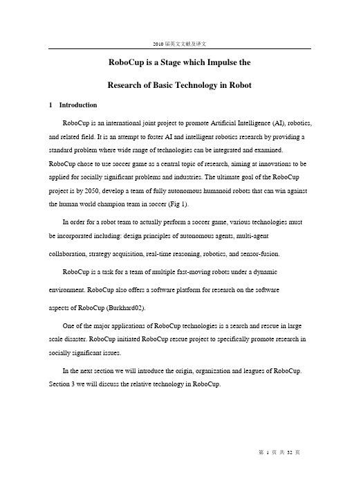
RoboCup is a Stage which Impulse theResearch of Basic Technology in Robot1 IntroductionRoboCup is an international joint project to promote Artificial Intelligence (AI), robotics, and related field. It is an attempt to foster AI and intelligent robotics research by providing a standard problem where wide range of technologies can be integrated and examined. RoboCup chose to use soccer game as a central topic of research, aiming at innovations to be applied for socially significant problems and industries. The ultimate goal of the RoboCup project is by 2050, develop a team of fully autonomous humanoid robots that can win against the human world champion team in soccer (Fig 1).In order for a robot team to actually perform a soccer game, various technologies must be incorporated including: design principles of autonomous agents, multi-agent collaboration, strategy acquisition, real-time reasoning, robotics, and sensor-fusion.RoboCup is a task for a team of multiple fast-moving robots under a dynamic environment. RoboCup also offers a software platform for research on the softwareaspects of RoboCup (Burkhard02).One of the major applications of RoboCup technologies is a search and rescue in large scale disaster. RoboCup initiated RoboCup rescue project to specifically promote research in socially significant issues.In the next section we will introduce the origin, organization and leagues of RoboCup. Section 3 we will discuss the relative technology in RoboCup.Figure 1. Soccer racing in the future2 The Origin, Organization and Leagues of RobocupThe concept of RoboCup was first introduced by professor of Alan Mackworth in 1993. The main goal of RoboCup is to propose a challenged research issue to develop robotic. Following a two-year feasibility study, in August 1995, an announcement was made on the introduction of the first international conferences and footballgames.Now RoboCup Soccer is divided into the following leagues: Simulation league(2D,3D), Small-size robot league (f-180), Middle-size robot league (f-2000), Fourlegged robot league, Humanoid league. In July 1997, the first official conference and games were held in Japan. The annual events attracted many participants and spectators.2.1RoboCup 2D-Simulation LeagueThe RoboCup 2D-simulation league uses a simulator called the Soccer Server to do the soccer simulation. The Soccer Server provides a standard platform for research into multiagent systems. The Soccer Server simulates the players, the ball and the field for a 2D soccer match.22 clients (11 for each team) connect to the server, each client controlling a single player. Every 100ms the Soccer Server accepts commands, via socket communication,from each client. The client sends low level commands (dash, turn or kick) to be executed (imperfectly) by the simulated player it is controlling. Clients can only communicate with each other using an unreliable, low bandwidth communication channel built into the Soccer Server. The Soccer Server simulates the (imperfect) sensing of the players, sending an abstracted (objects, e.g. players and ball, with direction, distance and relative velocity) interpretation of field of vision to the clients every 150ms. The field of vision of the clients is limited to only a part of the whole field. The Soccer Server enforces most of the basic rules of (human) soccer including off-sides, corner kicks and goal kicks and simulates some basic limitations on players such as maximum running speed, kicking power and stamina limitations (Bom99).An extra client on each team can connect a s a “coach”, who can see the whole field and send strategic information to clients when the play is stopped, for example for a free-kick. The Soccer Monitor (Fig 2) connects to the Soccer Server as another client and provides a 2D visualization of the game for a human audience. Other clients can connect in the same way to do things like 3D visualization, automated commentary and statistical analysis.There are no actual robots in this league but spectators can watch the action on a large screen, which looks like a giant computer game. Each simulated robot player may have its own play strategy and characteristic and every simulated team actually consists of a collection of programmers. Many computers are networked together in order for this competition to take place. The games last for about 10 minutes, with each half being 5 minutes duration.2. 2 RoboCup 3D-Simulation LeagueThe 3D competition makes use of the simulator that is based on the simulation system introduced at the RoboCup 2003 symposium and the spades simulationmiddleware systemFigure 3. RoboCup 3D-Simulation leagueFigure 2. RoboCup 2D-Simulation leagueintroduced at the RoboCup 2002 symposium. It can be downloaded from source forge (Fig 3). One of the goals for future 3D soccer competitions is to have simulated robots with articulated bodies, for example like humanoid robots. Prior to compiling and installing the rcssserver3D, you need to install a few software packages. You can compile and install rcssserver3D in two different ways, a "light" installation and the full installation. With the full installation, you get an additional library (called kerosin), which is useful to visualize objects nicely, especially articulated objects (this are objects consisting of more than one geometry linked with joints). These features are not (yet) required for the soccer simulation. The light installation, which is the default, you get a not so fancy OpenGL visualization. To enable the full installation, pass the "--enable-kerosin" flag to the `configure' shell script. For the generic installation instructions, see the text below the specific instructions here.Required libraries for the default installation:(1) spades- working versions: 1.0, older versions may also work;- get it at: /projects/ spades-sim;- description: agent middleware, handles timing issues and networking;- additional info: you need a recent version of expat for spades.(2) ruby- working versions: 1.8.0 or newer;- get it at: /;- description: scripting language;- additional info: if you compile ruby yourself, configure with enable-shared.(3) boost- working versions: 1.30.2, 1.31.0;- get it at: /;- description: c++ programming extensions.(4) ode- working versions: 0.039;- - get it at: /projects/ open- de;- -descriptions: for simulating articulated rigid body dynamics.(5) OpenGL, GLUTYou need the OpenGL and GLUT headers for the visualization. This may be dependent on your graphics card. (GLUT is the OpenGL Utility Toolkit).-part for example of XFree86-Mesa-devel;-you should get it with your linux distro.2.3 Small-size Robot LeagueThe field of play must be rectangular. The dimensions include boundary lines. Length: 4900mm, Width:3400 mm. A small-size RoboCup takes place between two teams of five robots each (Fig 4).Figure 4. Small-size robot leagueEach robot must conform to the dimensions as specified in the F180 rules: The robot must fit within a 180mm diameter circle and must be no higher than 15cm unless they use onboard vision. The robots play soccer on a green carpeted field that is 2.8m long by 2.3m wide with an orange golf ball. Robots come in two flavors, those with local on-board vision sensors and those with global vision. Global vision robots, by far the most common variety, use an overhead camera and off-field PC to identify and track the robots as they move around the field. The overhead camera is attached to a camera bar located 3m above the playing surface. Local vision robots have their sensing on the robot itself. The vision information is either processed on-board the robot or is transmitted back to the off-field PC for processing. An off-field PC is used to communication referee commands and, in the case of overhead vision, position information to the robots. Typically the off-field PC also performs most, if not all, of the processing required for coordination and control of the robots. Communications is wireless and typically uses dedicated commercial FM transmitter/receiver units although at least one team has used IRDA successfully.2.4 Middle Size LeagueTwo teams of 4 mid-sized robots with all sensors on-board play soccer on a field. Relevant objects are distinguished by colors. Communication among robots (if any) is supported on wireless communications. No external intervention by humans is allowed, except to insert or remove robots in/from the field.Figure 5. Middle Size League2. 5 The Four-Legged LeagueIn The Four-Legged League, participating teams have to use robots specified by the Competition Committee without any modification on its hardware.In 2004 there are choices of either using:-Sony Entertainment Robot AIBO ERS-210/210A, or-Sony Entertainment Robot AIBO ERS-7, or-A combination of both in the teamThe four main technical issues associated with the SSL are the following:Robust color processing and color tracking. The lighting at tournament halls is very irregular; there are shadows and unpredictable variations during a game. The software has to surmount these difficulties while processing video frames provided by inexpensive cameras. In recent years, most good teams have solved these issues, and we do not see them losing the robots or the ball.Robust mechanical design. A robot able to play at a good level in the SSL must be fast (1-2 m/s maximal speed) and able to resist strong collisions. Typically, SSL robots can fall from a table and continue playing. There has been a new emphasis in mechanical designduring the last two years with the introduction of such innovations as omni directional drive (Cornell 2000) and dribbling bars that allow robots to control the ball and pass it (Cornell 2001).Robust wireless communications. This might be considered the single most important unsolved issue in the SSL. Most teams use the same RF chips and this has led to significant interference problems in the past. Tournaments have become too long because it is very difficult to schedule simultaneous games. A solution such as WaveLan cards or Bluetooth modules will be explored in the future.Good programming of robot behavior. It can be safely said that most teams in the SSL have adopted a pure reactive design with simple strategic goals. The fact that the field of play is too small relative to the size of the robots means that it does not pay to compute too complicated strategies. The horizon of most systems is just a few frames into the future, since the robots are so fast relative to the size of the field. Thus, enlarging the field has to become a major research issue if more sophisticated strategies are to be programmed.Figure 6. 4 legged league Figure 7. Humanoid league2.6 Humanoid LeagueHumanoid robots show basic skills of soccer players, such as shooting a ball, or defending a goal. Relevant objects are distinguished by colors. External intervention by humans is allowed, as some of the humanoid robots are tele-operated.3 Viewing a Soccer Game as a Multi-Agent EnvironmentA soccer game is a specific but very attractive real time multi-agent environment from the viewpoint of distributed artificial intelligence and multi-agent research. If we regard a soccer team as a multi-agent system, a lot of interesting research issues will arise.In a game, we have two competing teams. Each team has a team-wide common goal, namely to win the game. The goals of the two teams are incompatible. The opponent team can be seen as a dynamic and obstructive environment, which might disturb the achievement of the common team goal. To fulfill the common goal, each team needs to score, which can be seen as a sub-goal. To achieve this subgoals, each team member is required to behave quickly, flexibly, and cooperatively; by taking local and global situations into account.The team might have some sorts of global (team-wide) strategies to fulfill the common goal, and both local and global tactics to achieve subgoals. However, consider the following challenges:-the game environment, i.e. the movement of the team members and the opponent team, is highly dynamic.-the perception of each player could be locally limited.-the role of each player can be different.-communication among players is limited; therefore, each agent is required to behave very flexibly and autonomously in real-time under the resource bounded situation.Summarizing these issues, a soccer team can be viewed as a cooperative distributed realtime planning scheme, embedded in a highly dynamic environment. In cooperative distributed planning for common global goals, important tasks include the generation of promising local plans at each agent and coordination of these local plans. The dynamics of the problem space, e.g. the changing rate of goals compared with the performance of each planner, are relatively large, reactive planning that interleaves the plan generation and execution phases is known to be an effective methodology at least for a single agent to deal with these dynamic problems.For cooperative plan schemes, there are frequent changes in the problem space or the observation of each agent is restricted locally. There is a trade-off between communication cost, which is necessary to coordinate the local plans of agents with a global plan, and the accuracy of the global plan (this is known as the predictability/responsiveness tradeoff). The study of the relationship between the communication cost and processing cost concerning the reliability of the hypotheses in FA/C, and the relationship between the modification cost of local plans and the accuracy of a global plan in PGP illustrate this fact. Schemes for reactive cooperative planning in dynamic problem spaces have been proposed and evaluated sometimes based on the pursuit game (predator-prey)(Hiroaki01). However, the pursuit game is a relatively simple game, the environment is basically for the study of a single agent architecture.We see that a robot soccer game will provide a much tougher, fertile, integrated, exciting, and pioneering evaluation environment for distributed artificial intelligence and multiagent research.4 Research Issues for Robocup with Real RobotsIn this section, we discuss several research issues involved in realizing real robots for RoboCup.(1) Design of RoboCup player and their control: Existing robot players have been designed to perform mostly single behavior actions, such as pushing/dribbling/rolling. A RoboCup player should be designed so that it can perform multiple subtasks such as shooting (including kicking), dribbling (pushing), passing, heading, and throwing a ball; which often involves the common behavior of avoiding the opponents. Roughly speaking, there are two ways to build RoboCup players:- Design each component separately, which is specialized for a single behavior and then assemble them into one.- Design one or two components that can per form multiple subtasks.Approach 1 seems easier to design but more difficult to build and vice versa. Since the RoboCup player should move around quickly it should be compact; therefore, approach 2 should be a new target for the mechanical design of the RoboCup player. We need compact and powerful actuators with wide dynamic ranges. Also, we have to develop sophisticated control techniques for as few as possible multiple behavior components with low energy consumption. The ultimate goal of a RoboCup player would be a humanoid type, that can run, kick and pass a ball with its legs and feet; can throw a ball with its arms and hands, and can do heading with its head. To build a team of humanoid type robots currently seems impossible.(2) Vision and sensor fusion: Visual information is a rich source of information to perceive, not only the external world, but the effects of the robot's actions as well. Computer Vision researchers have been seeking an accurate 3D geometry reconstructing from 2D visual information, believing in that the 3D geometry is the most powerful and general representation. This could be used in many applications, such as view generation for a video database, robot manipulation and navigation. However, the time-consuming 3D reconstruction may not be necessary nor optimally suited for the task given to the RoboCup player. In order to react to the situation in real time, the RoboCup player quickly needs information to select behavior for the situation, we are not suggesting a specialpurpose vision system, just that the vision is part of a complex system that interacts in specific ways with the world. RoboCup is one of these worlds, which would make clear the role of vision and evaluate the performance of image processing which has been left ambiguous in the computer vision field. In addition to vision, the RoboCup player might need other sensing devices such as: sonar, touch, and force/torque, to discriminate the situations that cannot be discriminated from only the visual information nor covered by visual information. Again, the RoboCup player needs the real time processing for multisensor fusion and integration. Therefore, the deliberative approaches with rough estimation using multi-sensor system do not seem suitable. We should develop a method of sensor fusion/integration for the RoboCup.(3) Learning RoboCup behaviors: The individual player has to perform several behaviors, one of which is selected depending on the current situation. Sinceprogramming the robot behaviors for all situations, considering the uncertainties insensory data processing and action execution is unfeasible, robot-learning methods seem promising. As a method for robot learning, reinforcement learning has recently been receiving increased attention with little or no a priori knowledge giving higher capability of reactive and adaptive behaviors (Balch00). However, almost all of the existing applications have been done only with computer simulations in a virtual world, real robot applications are very few(Silvia 99). Since the prominence of the reinforcement learning role is largely determined by the extent to which it can be scaled to larger and complex robot learning tasks, the RoboCup seems a very good platform. At the primary stage of the RoboCup tournament, one to one competition seems feasible. Since the player has to take the opponent's motions into consideration, the complexity of the problem is much higher than that of simple shooting without an opponent. To reduce the complexity, task decomposition is often used. Fredrik proposed a method for learning a shooting behavior avoiding a goal keeper (Fredrik00). The shooting and avoiding behaviors are independently acquired and they are coordinated through the learning. Their method still suffers from the huge state space and the perceptual liaising problem, due to the limited visual field. Kum proposed a reactive deliberation approach to the architecture for real time intelligent control in a dynamic environment (Kum99. He applied it to a one to one soccer-like game. Since his method needs global sensing for robot positions inside the field, it does not seem applicable to the RoboCup that allows the sensing capability only through the agents (see the rule section). At the final stage, a many-to-many competition is considered. In this case, collective behaviors should be acquired. Defining all the collective behaviors, as a team seems infeasible, especially, the situations where one of multiple behaviors should be performed. It is difficult to find a simple method for learning these behaviors, definition of social behaviors. A situation would not be defined as the exact positions of all players and a ball, but might be perceived as a pattern. Alternatives, such as"coordination by imitation," should be considered. In addition to the above, the problems related to the RoboCup such as task representation and environment modeling are also challenging ones. Of course, integration of the solutions for the problems mentioned above into a physical entity is the most difficult one.5 Relative Technology in RobocupThe robot football game is taken on by hardware or imitated robot human. The rule is similar to the true human football game. The research of robot football match taken by hardware is concerned with computer, automatic control, sensing technology, wireless communication, precise mechanism, imitated materials and numerous forward-position researches and synthesizes integration. Imitated robot football game is carried on the standard software platform and it fully embodies the technologies of control, communication, sensing and some other aspects. The key points of the researches are some advanced functions, such as cooperation in the system, dynamic decisions, timely plans, the learning of machine and some hot points in the current artificial intelligence. Therefore, in the realm of international artificial intelligence, robot football is regarded as a standard problem in the future 50 years, just as the international chess games between human and computer.The robot football game can do benefit to apply the theories of AI to practice. It also can help to examine the new thoughts, new techniques, and promote the related development of technology. A series of new techniques used by Robot football games will do favor to the development of social economy and culture. Robot football games are not only a kind of front competition with high techniques, but also provide amusement, enjoyment and incentive, which the true game provides. We can anticipate that this activity will produce tremendous market's need and new industrial opportunities, and will bring inestimable utilities of economy and society. The target of the research of RoboCup is to provide a test platform for the distributed system. In a specific way, it includes the research targets as follows:- The posture of robot. Now the robot uses wheel and bedrail, the human player don’t play with it in court. So we must build the robot like human such as gesture,structure and weight.- The body of robot. If the robot is full of iron and plastic, people are afraid of touch in it. So the robot must own the muscle and can collide with people.- The energy of robot. Now the soccer robot’s power is battery, but can only use few minutes. in the future, the soccer robot must run and move in 45-50 minutes, thatmeans the battery must has little volume, the light weight and full of power.- The skill of robot. Now the two-logger robot can move in stair. The best soccer robot is four-legged dog of SONY corporation. After 50 years, the robots must can run, move jump, shoot, dribble like human being. People can do, so the robots can do.- Intelligence of robot. The high level player plays with ball using their brain, so the intelligence of star must high-class. In 1997,IBM’s deep blue beat down Kasparov , but IBM use 16 RISK6000.so in the future, the micro computer in soccer robot must very well.- The sense of robot. The sense parts are arranged at will. for example, it can own six eyes, use sonar and wireless communication network, now the tech of sense can not solve the comprehension of image, the power of touch and the function andefficiency of inside sensor. So we must solve these problems.6 The Significance of Researching RobocupThinking carefully, we can suggest more contents and difficult points. We seem to have reasons to deny the imagination of “the battle between human and machine”. Because it is unimaginable to reach such achievement today.But look back to the history, nowadays, there are so many scientific achievements which are unimaginable for the forefathers, aren’t there? People will have an unusual eye on the scientific development in 50 years.It’s about half century from the first plane of which the Wright brothers’ having trial flight to the suc cessful landing on the moon of Aporo airship. While it’s also 50 years fromthe first computer to computer of “Deep blue” defeating human genius. Now we can see that we should not say “no” in advance for “the battle between human and machine” about 50 years later.Which we need now is the spirit of innovation, active participation. What we should do is to try our best to improve this process.It’s easy to see that we should innovate more. It contains outstanding progress of artificial life, energy power, ma terial and so on. And it’s also contains the great break of many sciences about the project of mechanics, electricity, control, information and computer which are related to the robot. We also need the intersection and combination of multi sciences.It’s the deep meaning of having the research of robot’s football. Although RoboCup is high-tech, only three players’ game, there shows some intricate scene. Such as robot bump the wall, two robots badger with each other, and some robotsare in the daze, don’t con cern about ball. People don’t understand why the robots’intelligence is not as good as the children.That is to say, it is not easy to make robot own the human’s intelligence-sense, thinking, and action, even the three older children. By 2050, scientists want to develop a team of fully autonomous robots, which can win against the human world champion team in soccer. It is a great goal.7 ConclusionsThis thesis discussed some main technologies in MAS and RoboCup. The aim is to let readers know more about Multi Agent System and cause the Agent-oriented technology mature faster.There are four steps in the development of programming: procedure orientedProgramming, module oriented Programming, object oriented Programming and the last step of Agent oriented Programming. Each process is a more and more abstract procedure,a more and more obscure modeling procedure, till in the end reaches to automatic design of programming. Therefore the emergence of Agent-oriented is inevitable for programming.RoboCup is a stage which impulse the research of basic technology in robot. AcknowledgementThis work was supported by the Foundation of Doctor Innovation in China under Grant (xm04-35)8 ReferencesBalch T, Mhybinette (2000), Social Potentials for Scalable Multi-Robot Formation.IEEE International Conf.on Robotics and Automation (ICRA 2000):73-80.Magnus Boman(1999), Agent Programming in RoboCup'99. AgentLink NewsLetter,(4), November 1999.Burkhard H D,et al (2002),The Road to RoboCup 2050. IEEE Robotics &Automation Magazine. Jun. 2002: 31-38.Cai Qing-sheng, Zhang Bo (2003), An agent team reinforcement learning model and its application. (J). Journal of Computer Research and Development.2003,37(9): 1087-1093. In China.Cheng Xian-yi (2003), Agent Computing. Haerbin(China): Hei Longjiang science and technology press. 2003.Cheng Xian-yi et al(2004),.Reinforcement Learning in Simulation RoboCup Soccer.Proceeding of 2004 International Conference on Machine Learning andCybernetics(ICML2004),in China, IEEE Catalog Number:04EX826.Fredrik Heintz (2000), RoboSoc a System for Developing RoboCup Agents for Educational Use. Master's thesis, Department of Computer and InformationScience, Link.oping university, March 2000.Hiroaki Y et al (2001), A Distributed Control Scheme for Multiple Robotic Vehicles to Make Group Forma- tions.Robotics and Autonomous systems,2001, 125 Silvia Coradeschi and Jacek Malec(1999), How to make achallenging AI course .enjoyableusing the RoboCup soccer simulation system. In RoboCup-98:TheSecond RobotWorld Cup Soccer Games and Conference, pages 120{124.Springer verlag, 1999Johan Kummeneje, David Lyb.ack, and H_akan L. Younes (1999), UBU – an objectoriented RoboCup Team. In Johan Kummeneje and Magnus Boman,editors, Int7 1999 Papers. 1999.Johan Kummeneje (1999), Simulated Robotic Soccer and the Use of Sociology in Real Time Mission Critical Systems. In L. R. Welch and M. W. Masters,editors, Proceedings of RTMCS Workshop, IEEE, December 1999。
工业机器人的介绍外文文献翻译、中英文翻译、外文翻译
外文原文Introduction to Industrial RobotsIndustrial robets became a reality in the early 1960’s when Joseph Engelberger and George Devol teamed up to form a robotics company they called “Unimation”. Engelberger and Devol were not the first to dream of machines that could perform the unskilled, repetitive jobs in manufacturing. The first use of the word “robots” was by the Czechoslovakian philosopher and playwright Karel Capek in his play R.U.R.(Rossum’s Universal Robot). The word “robot” in Czech means “worker” or “slave.” The play was written in 1922.In Capek’s play , Rossum and his son discover the chemical formula for artificial protoplasm. Protoplasm forms the very basis of life.With their compound,Rossum and his son set out to make a robot.Rossum and his son spend 20 years forming the protoplasm into a robot. After 20 years the Rossums look at what theyhave created and say, “It’s absurd to spend twenty years making a man if we can’t make him quicker than nature, you might as w than nature, you might as well shut up shop.” ell shut up shop.”The young Rossum goes back to work eliminating organs he considers unnecessary for the ideal worker. The young Rossum says, “A man is something that feels happy , plays piano ,likes going for a walk, and in fact wants to do a whole lot of things that are unnecessary … but a working machine must not play piano, must not feel happy, must not do a whole lot of other things. Everything that doesn’t contribute directly to the progress of work should be eliminated.”A half century later, engi neers began building Rossum’s robot, not out of artificial protoplasm, but of silicon, hydraulics, pneumatics, and electric motors. Robots that were dreamed of by Capek in 1922, that work but do not feel, that perform unhuman or subhuman, jobs in manufacturing plants, are available and are in operation around the world.The modern robot lacks feeling and emotions just as Rossum’s son thought it should. It can only respond to simple “yes/no” questions. The moderrn robot is normally bolted to the floor. It has one arm and one hand. It is deaf, blind, and dumb. In spite of all of these handicaps, the modern robot performs its assigned task hour after hour without boredom or complaint.A robot is not simply another automated machine. Automation began during the industrial revolution with machines that performed jobs that formerly had been done by human workers. Such a machine, however , can do only the specific job for which it was designed, whereas a robot can perform a variety of jobs.A robot must have an arm. The arm must be able to duplicate the movements of a human worker in loading and unloading other automated machines, spraying paint, welding, and performing hundreds of other jobs that cannot be easily done with conventional automated machines.DEFINITION OF A ROBOTThe Robot Industries Association(RIA) has published a definition for robots in an attempt to clarify which machines are simply automated machines and which machines are truly robots. The RIA definition is as follows:“A robot is a reprogrammabl reprogrammable e multifunctional manipulator designed to move material, parts, tools, or specialized devices through variable programmed motions for the performance of a variety of tasks.”This definition, which is more extensive than the one in the RIA glossary at the end of this book, is an excellent definition of a robot. We will look at this definition, one phrase at a time, so as to understand which machines are in fact robots and which machines are little more than specialized automation.First, a robot is a “reprogrammable multifunctional manipulator.” In this phrase RIA tells us that a robot can be taught (“reprogrammed”) to do more than one job by changing the informaion stored in its memory. A robot can be reprogrammed to load and unload machines, weld, and do ma and unload machines, weld, and do many other jobs (“multifunctional”). A robot is a ny other jobs (“multifunctional”). A robot is a“manipulator”. A manipulator is an arm( or hand ) that can pick up or move things. At this point we know that a robot is an arm that can be taught to do different jobs.The definition goes on to say that a ro The definition goes on to say that a robot is “designed to move material, parts, bot is “designed to move material, parts, tools, or specialized devices.” Material includes wood,steel, plastic, cardboard… anything that is used in the manufacture of a product.A robot can also handle parts that have been manufactured. For example, a robot can load a piece of steel into an automatic lathe and unload a finished part out of the lathe. In addition to handling material and parts, a robot can be fitted with tools such as grinders, buffers, screwdrivers, and welding torches to perform useful work.Robots can also be fitted with specialized instruments or devices to do special jobs in a manufacturing plant. Robots can be fitted with television cameras for inspection of parts or products. They can be fitted with lasers to accurately mearure the size of parts being manufactured.The RIA definition closes with the phrase,”…through variable programmed motions for the performance of a variety of tasks.” This phrase emphasizes the fact that a robot can do many different jobs in a manufacturing plant. The variety of jobs that a robot can do is limited only by the creativity of the application engineer. JOBS FOR ROBOTSJobs performed by robots can be divided into two major categories:hazardous jobs and repetitive jobs. Hazardous JobsMany applications of robots are in jobs that are hazardous to humans. Such jobs may be considered hazardous because of toxic fumes, the weight of the material being handled, the temperature of the material being handled, the danger of working near rotating or press machinery, or environments containing high levels of radiation. Repetitive JobsIn addition to taking over hazardous jobs, robots are well suited to doingextremely repetitive jobs that must be done in manufacturing plants.many jobs in manufacturing plants require a person to act more like a machine than like a human.The job may be to pick a piece up from here and place it there. The same job is donehundreds of times each day. The job requires little or no judgment and little or no skill.This is not said as a criticism of the person who does the job , but is intended simplyto point out that many of these jobs exist in industry and must be done to complete themanufacture of products. A robot can be placed at such a work station and can perform the job admirably without complaining or experiencing the fatigue and boredom normally associated with such a job.Although robots eliminate some jobs in industry, they normally eliminate jobs thathumans should never have been asked to do. Machines should perform as machines doing machine jobs, and humans should be placed in jobs that require the use of their ability,creativity, and special skills.POTENTIAL FOR INCREASED PRODUCTIVITYIn addition to removing people from jobs they should not have been placed in,robots offer companies the opportunity of achieving increased productivity. Whenrobots are placed in repetitive jobs they continue to operate at their programmed pacewithout fatigue. Robots do not take either scheduled or unscheduled breaks from thejob. The increase in productivity can result in at least 25% more good parts beingproduced in an eight-hour shift. This increase in productivity increases the company'sprofits, which can be reinvested in additional plants and equipment. This increase in productivity results in more jobs in other departments in the plant. With more parts being produced, additional people are needed to deliver the raw materials to the plant, to complete the assembly of the finished products, to sell the finished products, and to deliver the products to their destinations.ROBOT SPEEDAlthough robots increase productivity in a manufacturing plant, they are notexceptionally fast. At present, robots normally operate at or near the speed of a human operator. Every major move of a robot normally takes approximately one second. Fora robot to pick up a piece of steel from a conveyor and load it into a lathe may requireten different moves taking as much as ten seconds. A human operator can do the samejob in the same amount of time . The increase in productivity is a result of theconsistency of operation. As the human operator repeats the same job over and overduring the workday, he or she begins to slow down. The robot continues to operate at its programmed speed and therefore completes more parts during the workday.Custom-built automated machines can be built to do the same jobs that robots do.An automated machine can do the same loading operation in less than half the timerequired by a robot or a human operator. The problem with designing a special machine is that such a machine can perform only the specific job for which it was built. If any change is made in the job, the machine must be completely rebuilt, or the machine must be scrapped and a new machine designed and built. A robot, on the other hand, could be reprogrammed and could start doing the new job the same day.Custom-built automated machines still have their place in industry. If a companyknows that a job will not change for many years, the faster custom-built machine isstill a good choice.Other jobs in factories cannot be done easily with custom-built machinery. For these applications a robot may be a good choice. An example of such an application is spray painting. One company made cabinets for the electronics industry. They made cabinets of many different sizes, all of which needed painting. It was determined that it was not economical for the company to build special spray painting machines for each of the different sizes of enclosures that were being built. Until robots were developed, the company had no choice but to spray the various enclosures by hand.Spray painting is a hazardous job , because the fumes from many paints are both toxic and explosive. A robot is now doing the job of spraying paint on the enclosures.A robot has been “taught” to spray all the different sizes of enclosures that thecompany builds. In addition, the robot can operate in the toxic environment of the spray booth without any concern for the long-term effect the fumes might have on aperson working in the booth.FLEXIBLE AUTOMATIONRobots have another advantage: they can be taught to do different jobs in the manufacturing plant. If a robot was originally purchased to load and unload a punch press and the job is no longer needed due to a change in product design, the robot can be moved to another job in the plant. For example, the robot could be moved to the end of the assembly operation and be used to unload the finished enclosures from a conveyor and load them onto a pallet for shipment.ACCURACY AND REPEATABILITYOne very important characteristic of any robot is the accuracy with which it can perform its task. When the robot is programmed to perform a specific task, it is led to specific points and programmed to remember the locations of those points. After programming has been completed, the robot is switched to “run” and the program is executed. Unfortunately, the robot will not go to the exact location of any programmed point. For example, the robot may miss the exact point by 0.025 in. If 0.025 in. is the greatest error by which the robot misses any point- during the first execution of the program, the robot is said to have an accuracy of 0.025 in.In addition to accuracy , we are also concerned with the robot’s s repeatability. The In addition to accuracy , we are also concerned with the robot’repeatability of a robot is a measure of how closely it returns to its programmed points every time the program is executed. Say , for example, that the robot misses a programmed point by 0.025 in. the first time the program is executed and that, during the next execution of the program, the robot misses the point it reached during the previous cycle by 0.010 in. Although the robot is a total of 0.035 in. from the original programmed point, its accuracy is 0.025 in. and its repeatability is 0.010 in.THE MAJOR PARTS OF A ROBOTThe major parts of a robot are the manipulator, the power supply, and the controller.The manipulator is used to pick up material, parts, or special tools used in manufacturing. The power supply suppplies the power to move the manipulator. The controller controls the power supply so that the manipulator can be taught to perform its task.外文翻译工业机器人的介绍工业机器人的介绍20世纪60年代当约瑟夫和乔治合作创立了名为Unimation 的机器公司,工业机器人便成为了一个事实。
四足机器人必读外文文献
四足机器人必读外文文献四足机器人是一种能够在复杂环境中行走、爬行和攀爬的机器人。
在机器人领域,四足机器人是一个热门的话题,因为它们可以应用于许多领域,如搜索和救援、军事、医疗和工业生产等。
以下是四足机器人必读的外文文献:1. Raibert, M. H. (1986). Legged robots that balance. MIT Press.这本书介绍了一个名为“谷仓狗”的四足机器人,它可以在不稳定的表面上平衡。
这本书提供了一个基本的框架,以便设计和控制其他类型的四足机器人。
2. Buehler, M., & Iagnemma, K. (2005). The DARPA grand challenge: the autonomous vehicle revolution. Springer.这本书介绍了2004年DARPA大挑战中的一些成功的四足机器人,这些机器人可以在困难的地形上行驶。
这些机器人的设计和控制方法可以为今后的四足机器人提供参考。
3. Kimura, H., & Hirose, S. (2005). Design and control of quadruped walking robots. World Scientific.这本书重点介绍了四足机器人的设计和控制。
它包括了许多重要的话题,如运动学、动力学、行走模式、传感器以及控制系统等。
4. Grizzle, J. W., Hurst, J. W., Morris, B., & Rizzi, A.A. (2014). Robotics for engineers. Cambridge University Press.这本书提供了一个广泛的介绍,涵盖了机器人技术的各个方面。
其中包括四足机器人的设计和控制,以及它们在各种应用领域中的应用。
5. Tsagarakis, N. G., & Caldwell, D. G. (2015). Humanoid robotics: a reference. Springer.虽然这本书主要关注人形机器人,但它也包括了一章介绍四足机器人。
工业机器人外文参考文献
工业机器人外文参考文献工业机器人外文参考文献1. Gao, Y., & Chen, J. (2018). Review of industrial robots for advanced manufacturing systems. Journal of Manufacturing Systems, 48, 144-156.2. Karaman, M., & Frazzoli, E. (2011). Sampling-based algorithms for optimal motion planning. The International Journal of Robotics Research, 30(7), 846-894.3. Khatib, O. (1986). Real-time obstacle avoidance for manipulators and mobile robots. The International Journal of Robotics Research, 5(1), 90-98.4. Lee, J. H., & Kim, E. B. (2019). Energy-efficient path planning for industrial robots considering joint dynamics. Journal of Mechanical Science and Technology, 33(3),1343-1351.5. Li, D., Li, Y., Wang, X., & Li, H. (2019). Design and implementation of a humanoid robot with flexible manipulators. Robotica, 37(12), 2008-2025.6. Liu, Y., Ren, X., & Wang, T. (2019). A novel adaptive fuzzy sliding mode control for a nonholonomic mobile robot. Soft Computing, 23(3), 1197-1209.7. Loh, A. P., & Tan, K. K. (2014). Vision-based controlof industrial robots using an adaptive neural network. Robotics and Computer-Integrated Manufacturing, 30(2), 177-184.8. Niemeyer, G., & Slotine, J. J. (1990). Stable adaptive teleoperation. The International Journal of Robotics Research, 9(1), 85-98.9. Park, J. Y., & Cho, C. H. (2018). Optimal path planning for industrial robots using a hybrid genetic algorithm. International Journal of Precision Engineering and Manufacturing, 19(5), 755-761.10. Wang, Z., Wang, X., & Liu, Y. (2019). Design and analysis of a novel humanoid robot with intelligent control. International Journal of Advanced Manufacturing Technology, 102(5-8), 1391-1403.。
- 1、下载文档前请自行甄别文档内容的完整性,平台不提供额外的编辑、内容补充、找答案等附加服务。
- 2、"仅部分预览"的文档,不可在线预览部分如存在完整性等问题,可反馈申请退款(可完整预览的文档不适用该条件!)。
- 3、如文档侵犯您的权益,请联系客服反馈,我们会尽快为您处理(人工客服工作时间:9:00-18:30)。
Keywords: forward kinematics; sensor network; sensor fusion; FPGA; industrial robot1. IntroductionFlexible manipulator robots have wide industrial applications, with handling and manufacturing operations being some of the most common [1-3]. High-precision and high-accuracy in robot operations require the study of robot kinematics, dynamics and control [4]. The aim of forward kinematics is to compute the position and orientation of the robot end effector as a function of the angular position of each joint [1]. The online estimation of the forward kinematics can contribute to improve the controller performance by considering the joints’ motion collectively. Therefore, the precision and accuracy of such information is essential to the controller in order to increase its performance in real robotic operations.Commercially available motion controllers use a single sensor for each joint to estimate the robot’s angular position; the most common sensor is the optical encoder [5-11], which provides a high-resolution feedback to the controller. However, it only gives information on the servomotor position and any deformations caused by joint flexibilities cannot be monitored [6,12], decreasing the robot’s accuracy. This problem is more evident in open-chain robots. Moreover, the provided information is relative, which means that it is impossible to estimate the initial position of the robot. Another sensor that is widely used in the estimation of the angular position of the robot joints is the gyroscope; it provides a measurement of angular rate of change, requiring the accumulated sum over time to estimate the angular position. Despite the fact that they can detect some nonlinearities that cannot be estimated with encoders, the quantized, noisy signal causes accumulated errors when angular position is required [13-15]. Furthermore, the estimated angular position is relative, which does not permit one to know the initial angular position of the robot joints. A good sensor that provides an absolute measurement is the accelerometer and it can be used to estimate the robot angularposition [5,16-20]. Nevertheless, the signal obtained is noisy and contains much information that needs preprocessing before being used [21].Two main issues need to be solved when the robot forward kinematics is required: the problems of using a single sensor to estimate the angular position of the joints and the online estimation of the forward kinematics. In this perspective, sensor fusion techniques improve the accuracy of the monitored variables, but at the expense of high-computational loads [22], which complicate the online estimation of the forward kinematics. Some works combine sensor fusion techniques and forward kinematics estimation. For example, in [7] accelerometer and encoder signals are fused using a disturbance observer to compensate some nonlinearities and a reset state estimator for position estimation; experimentation is performed on a linear motor positioning system, which requires no forward kinematics estimation. Another work that fuses encoder and accelerometer signals is presented in [16], where the forward kinematics of two links in a 6-DOF robot is calculated; different versions of an extended Kalman filter are used for sensor fusion. However, the efficacy of the proposed algorithm is demonstrated offline. Other works attempt to fuse more than two different sensors. In [12] the fusion of encoder, accelerometer and interferometer through a Kalman filter is presented to estimate the position of a parallel kinematic machine, but the analysis is limited to one-axis movement. In [6] camera, accelerometer and gyroscope sensors are combined through a kinematic Kalman filter for position estimation of a planar two-link robot to facilitate the forward kinematics estimation. In [23,24] a hardware-software architecture for sensor network fusion in industrial robots is PCs to process all the data collected from the sensors and to control the robot are used. However, they use the sensor fusion to estimate the robot contact force and the forward kinematics are estimated only from the encoder signals.Reported works note the limitations of using a single sensor to estimate robots’ forward kinematics. Besides, forward kinematics is limited to a couple of joints due to the equations’ complexity. Therefore, the online forward kinematics estimation problem for multi-axis robots stillrequires additional efforts. Due to this, a dedicated processor capable of filtering and fusing the information of several sensors would be desirable. Also, multi-axis forward kinematics estimation in an online fashion would be advantageous.The contribution of this work is performed of two stages: the improvement of the sensing method of conventional motion controllers through proposal of an encoder-accelerometer-based fused smart sensor network. Furthermore, we propose a smart processor capable of processing all the sensed encoder-accelerometer signals so as to obtain online forward kinematics estimation of each joint of a six-degree-of-freedom (6-DOF) industrial robot. The smart processor is designed using field-programmable gate arrays (FPGA) owing to their parallel computation capabilities and reconfigurability. It is designed through the combination of several methods and techniques to achieve online operation. The smart processor is able to filter and to fuse the information of the sensor network, which contains two primary sensors: an optical encoder, and a 3-axis accelerometer; and then to obtain the robot forward kinematics for each joint in an online fashion. The sensor network is composed of six encoders and four 3-axis accelerometers mounted on the robot. An experimental setup was carried out on a 6-DOF PUMA (Programmable Universal Manipulation Arm) robot, demonstrating the performance of the proposed fused smart sensor network through the monitoring of three real-operation-oriented 3D trajectories. Moreover, additional experiments were carried out whereby the forward kinematics obtained with the proposed methodology is compared against the obtained through the conventional method of using encoders. An improvement in the measurement accuracy is found when the proposed methodology is used.2.MethodologyThe use of accelerometers on 6-DOF PUMA robots requires placing them adequately in specific positions. The combination of accelerometers and encoders make up the sensor network that needs to be processed in order to estimate the angular position of each joint and the forward kinematics accurately. In this section, the placement of the sensor network on the PUMA robot is presented. Then, the FPGA-based forward kinematics smart processor is clearly described.. Sensor NetworkA sensor network is an array of diverse types of sensors to monitor several variables [25,26]; in this case the angular position of the joint flexibilities of the robot. The sensor network arranged on the robot is presented in Figure 1. Figure 1(a) depicts the position of the accelerometers on the robot. xiA, yiA and ziA are the measurements of each axis from the accelerometer iA. Figure 1(b) is a schematic of the robot including its link parameters. i represents the angular position of joint i. ia and id represents the robot physical dimensions. Also, the localization of encoders iE is shown.Figure 1. Sensor network location on the robot.(a) Accelerometer placement. (b) Schematicshowing the parameters that describe the robot.For this work, the forward kinematics estimation consists on the estimation of the joint angular position (i), the spatial position of each joint (iiiZYX,,); and the roll (i), pitch (i), and yaw (i) angles [1]. Such angles represent the rotation along the000,,XYZ axes, respectively, required to obtain the orientation of each joint.Angular Joint PositionThe joint angular position is calculated with both encoder and accelerometer sensors. Afterwards, the obtained information is fused through a Kalman filter. In the case of the encoders, the angular joint position Ei can be calculated using Equation (1), where iEis the accumulated count given by encoder i; SF is a scale factor relating the minimum angular displacement required to obtain a count in the encoder, the units are rad/counts:Concerning the estimation of the angular joint position using accelerometers Ai, the corresponding equations are summarized in Table 1. In the case of the first angular position, the joint always moves perpendicularly to gravity force. Therefore, an accelerometer cannot detect the position changes in this joint. For this reason, only the encoder information is using for the angular position estimation in joint 1. Such equations assume that the accelerometers provide a noise-free signal, which is unrealistic; thus, the signal requires a filtering stage before being used.。