安全阀计算手册样本
安全阀的计算模板
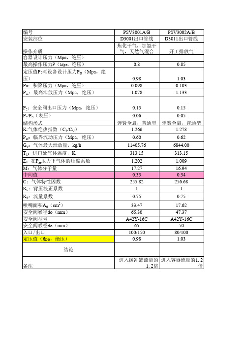
PSV3005/A,B D3007出口管线 中变气 2.75 3.015 0.3015 3.3165 0.15 0.02 弹簧全启,普通型 1.359 1.78 29686.80 313.15 1.465 10.83 0.34 262.27 1 0.75 38.50 70.03 A42Y-40 80 100/150 3.02
进入缓冲罐流量的1.2倍 进入容器流量的1.2倍
编号 安装部位 操作介质 容器设计压力(Mpa,绝压) 最高操作压力P(Mpa,绝压) 定压值Ps≤设备设计压力PD(Mpa,绝压) Pa:积聚压力(Mpa,绝压) Pm:最高泄放压力(Mpa,绝压) P2:安全阀出口压力(Mpa,绝压) P2/PS(表压) 结构形式 K:气体绝热指数(CP/CV) Pcf:临界流动压力(Mpa,绝压) Gv:气体最大泄放量,kg/h T1:进口处气体温度,K Z:在Pm压力下气体的压缩系数 M:气体分子量 中间值 C:气体特性因数 Kb:背压校正系数 KF:流量系数 喷嘴面积A0(cm2) 安全阀喉径do(mm) 安全阀型号 安全阀喉径do(mm) 入口/出口 定压值(Mpa,绝压) 结论
进入容器流量的1.2倍 进入容器流量的1.2倍
编号 安装部位 操作介质 容器设计压力(Mpa,绝压) 最高操作压力P(Mpa,绝压) 定压值Ps≤设备设计压力PD(Mpa,绝压) Pa:积聚压力(Mpa,绝压) Pm:最高泄放压力(Mpa,绝压) P2:安全阀出口压力(Mpa,绝压) P2/PS(表压) 结构形式 K:气体绝热指数(CP/CV) Pcf:临界流动压力(Mpa,绝压) Gv:气体最大泄放量,kg/h T1:进口处气体温度,K Z:在Pm压力下气体的压缩系数 M:气体分子量 中间值 C:气体特性因数 Kb:背压校正系数 KF:流量系数 喷嘴面积A0(cm2) 安全阀喉径do(mm) 安全阀型号 安全阀喉径do(mm) 入口/出口 定压值(Mpa,绝压) 结论
安全阀计算
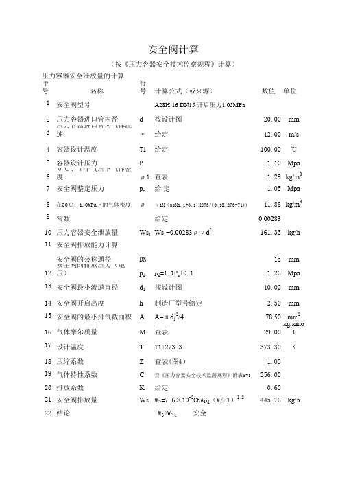
序号名称符号计算公式(或来源)数值单位1安全阀型号A28H-16 DN15 开启压力1.05MPa 2压力容器进口管内径d 按设计图
20.00mm 3压力容器进口管内气体流速ν给定
12.00m/s 4容器设计温度T1给定
100.00℃5容器设计压力P
1.10Mpa 60℃、1个气压下气体密度ρ1查表
1.29kg/m 37安全阀整定压力p s 给 定
1.05Mpa 8在50℃、1.0MPa下的气体密度ρρ1X(psX1.1+0.1)X273/(0.1X(273+T1))11.88kg/m 39常数给定
0.0028310压力容器安全泄放量Ws 1Ws 1=0.00283ρνd 2161.33kg/h 11安全阀的公称通径DN
15mm 12安全阀的排放压力(绝压)p d p d =1.1P s +0.1 1.26Mpa 13安全阀最小流道直径d 1按设计图
10.00mm 14安全阀开启高度h 制造厂型号给定 2.50mm 15安全阀的最小排气截面积A A=πd 12/4
78.50mm 216气体摩尔质量M 查表
29.00kg/kmol 17设计温度T T1+273.3
373.30K 18压缩系数Z 查表(图4)
1.0019气体特性系数C 查《压力容器安全技术监督规程》附表5-1356.0020排放系数K 给定
0.6021安全阀排放量Ws Ws=7.6×10⁻²CKAp d (M/ZT)
1/2
445.76kg/h 22结论 W S >Ws 1 安全安全阀计算
(按《压力容器安全技术监察规程》计算)
压力容器安全泄放量的计算
安全阀排放能力计算。
安全阀计算-容规99

安全阀排放能力计算书
制造指令:三器组件:FCES2500K
1.0冷凝器、油分离器安全阀口径计算
1.1依据标准:根据GB150-1998《钢制压力容器》附录B“超压泄放装置”
1.2计算过程
s1
对于制冷剂采用R22,其P0/P d=0.0457
大于(2/(k+1))k/(k-1)=0.0165
50.82
s2
油分离器安全泄放量(W s2)的计算
对于制冷剂采用R22,其P0/P d=0.0456621大于(2/(k+1))k/(k-1)=0.016499757
50.82
根据GB150-1998《钢制压力容器》附录B“超压泄放装置”B4.3条之b)款规定,油分离器与
冷凝器之间用足够大的管道连接,且之间无截止阀,故可以看作一个容器,故两器的
1冷凝器与油分离器系统安装两个相同的安全阀,在这种情况下单个安全阀的泄放量是总泄放由设计可看出,冷凝器与油分离器的容器系统安装两个相同安全阀的情况下,
单个安全阀最小流道直径(阀座喉径)应不小于10.5mm
2.0蒸发器安全阀口径计算
2.1依据标准:根据GB150-1998
《钢制压力容器》附录B“超压泄放装置”
2.2计算过程
s 0.82
由设计可看出,蒸发器只安装一个安全阀的情况下,安全阀最小流道直径应不小于
9mm
编制:校核:审核:。
安全阀计算

c
Kp Kg k Pe Pa △Pz Pg P Tb A E1
根据第6.1.6条规定 表6-1 表6-1 K=Kp.Kg
二
过热器出口集箱安全阀 排放能力计算
1 2
安全阀型号 安全阀个数 n
A48sH-25 取用
DN100 1 只
名 图
3 4 安全阀喉径 安全阀提升高度
称 号
d0 h te Kp Kg k P A E2
安全阀排汽能力计算
阀门样本 阀门样本 h≥d0/4
共 第
65.00
页 页
mm
锅炉额定蒸汽温度 -1 -2 8 9 10 11 压力修正系数 过热修正系数 安全阀入口处蒸汽比容修 正系数 安全阀入口处蒸汽压力 排汽面积 安全阀排汽能力
315.00 表6-1 √1000/(1000+2.7(Te-Tb) K=Kp.Kg 1.04Pe nX(1/4)πd02 CA(10.2P+1)K 1.00 0.879 0.88 1.664 3318.21 12318.843
名 图
序号 项目
称 号
安全阀排汽能力计算
符号 计算公式
共 第
数值
页 页
单位
一 锅筒安全阀排汽能力计算 1 2 3 4 5 6 7 8 9 10 11 12 13 安全阀型号 安全阀个数 安全阀喉径 安全阀提升高度 排放系数 压力修正系数 过热修正系数 安全阀入口处蒸汽比容修 正系数 锅炉额定压力 锅筒出口安全阀较低始启 压力与额定压力差值 流动阻力 工作压力 蒸汽入口处压力 锅筒饱和温度 14 15 排汽面积 安全阀排汽能力 n d0 h A48Y-25 取用 阀门样本 阀门样本 h≥d0/4 0.235 1.00 1.00 1.00 1.60 0.06x1.1Pe 0.11 0.16 Pg=Pe+△Pz Pg+Pa=1.76+0.1056 1.76 1.87 206.00 nX(1/4)πd02 CA(10.2P+1)K 6636.42 31236.582 Mpa Mpa Mpa Mpa Mpa ℃ mm2 Kg/h mm DN100 2 65.安全阀总排放能力
安全阀计算书
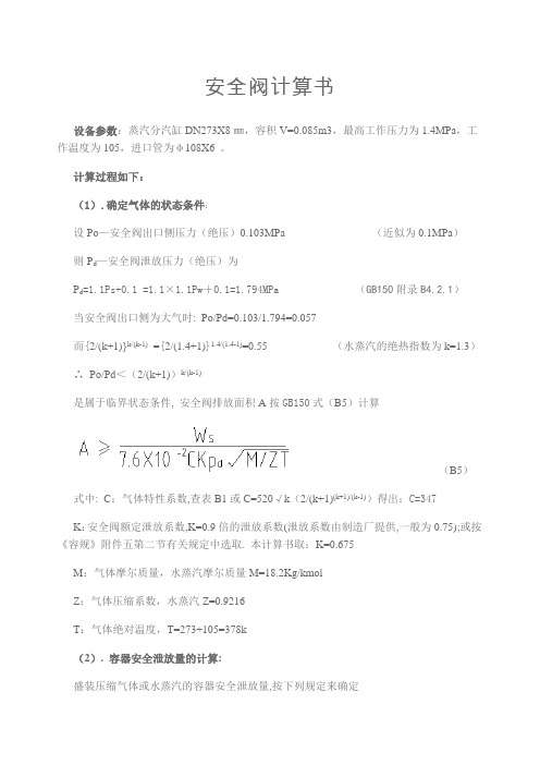
安全阀计算书设备参数:蒸汽分汽缸DN273X8㎜,容积V=0.085m3,最高工作压力为1.4MPa,工作温度为105,进口管为φ108X6 。
计算过程如下:(1).确定气体的状态条件:设Po—安全阀出口侧压力(绝压)0.103MPa (近似为0.1MPa)则P d—安全阀泄放压力(绝压)为P d=1.1Ps+0.1 =1.1×1.1Pw+0.1=1.794MPa (GB150附录B4.2.1)当安全阀出口侧为大气时: Po/Pd=0.103/1.794=0.057而{2/(k+1)}k/(k-1)={2/(1.4+1)}1.4/(1.4-1)=0.55 (水蒸汽的绝热指数为k=1.3)∴Po/Pd<(2/(k+1))k/(k-1)是属于临界状态条件, 安全阀排放面积A按GB150式(B5)计算(B5)式中: C:气体特性系数,查表B1或C=520√k(2/(k+1)(k+1)/(k-1))得出:C=347K:安全阀额定泄放系数,K=0.9倍的泄放系数(泄放系数由制造厂提供,一般为0.75);或按《容规》附件五第二节有关规定中选取. 本计算书取:K=0.675M:气体摩尔质量,水蒸汽摩尔质量M=18.2Kg/kmolZ:气体压缩系数,水蒸汽Z=0.9216T:气体绝对温度,T=273+105=378k(2). 容器安全泄放量的计算:盛装压缩气体或水蒸汽的容器安全泄放量,按下列规定来确定a.对压缩机贮罐或水蒸汽的容器,分别取压缩机和水蒸汽发生器的最大产气量;b.气体储罐等的安全泄放量按GB150式(B1)计算Ws=2.83×10⁻³ρυd2㎏/h (B1)ρ:为排放压力下的气体密度㎏/m3.ρ=M/Vρ=M(分子量)×Pw’(排放绝对压力)×T标/P (V×T)空气分子量 M=18.2 标准状态理想气体摩尔体积 V=22.4排放绝对压力 Pw’=17.94㎏/㎝2大气绝对压力 P=1.03㎏/㎝2将M、Pw’、 T标、P、V、T代入上式得ρ=18.2×17.94×273/1.03×22.4×378=10.22㎏/m3υ:容器在工作压力下的进口管的气体流速m/s;根据HG/T20570.6-95中表2.0.1饱和水蒸汽管径DN :200~100mm时,υ:35~25m/s 所以本计算书取:υ=25m/sd:进气管内径, d=92mm将上述ρ、ν、d代入式(B1)得Ws=2.83×10-3×10.22×25×922 =6120㎏/h(3). 安全阀排放面积的计算:将上述Ws、C、K、P d、M、Z、T代入上式(B5)可计算出:A=873.3mm2根据设备工况选用全启式安全阀则:A=0.785d02=873.3mm2安全阀喉径为:d0=33.4㎜根据安全阀公称直径与喉径对照表表1 安全阀公称直径与喉径对照表∴选用公称直径DN80的全启式安全阀.。
安全阀计算书

Wdr额定排量
=5.25X A X Kdr X Ksh X Pdr
=30192.28Kg/h
Wdr>Ws所以排量足够
安全阀反作用力计算
参
数
1
型号
A64Y-16C
6
通道面积A
31400mm2
2
规格
DN300
7
排放出口面积Ac
125600mm2
3
开启压力Ps(G)
0.14MPa
8
绝热指数k
1.3
4
排放压力P(A)
0.2442MPa
9
压缩指数Z
1
5
排量系数Kd
0.75
10
大气压力Pd
0.1MPa
计算排放出口截面绝对压力Pc(MPa)
当Pc小于大气压时排放速度为亚音速,排放反作用力按下式计算:
C:气体特征系数:
Kdr:额定排量系数:0.75
Z:压缩系数:
Ksh:过热修正系数:1.00
μ:粘度:cp
Kv:粘度修正系数:
口径计算
As所需流道面积:
=Ws/(5.25 X Kdr X Ksh X Pdr)=11640/(5.25*0.75*1*0.2442)
=12105.61mm2
选择流道面积(喉口直径200):A=31400mm2
M:摩尔质量18Kg/Kmol
ρ:密度Kg/m
Ps:整定压力:0.14MPa
Pdr:额定排放压力:Pdr=Ps(1+△P0)+0.1= 0.2442MPa
Pb:背压:MPa
Kb:背压修正系数:1.00T:Βιβλιοθήκη 放温度:273+120 K
安全阀选型计算书

安全阀选型计算书编写:张景富西安协力动力科技有限公司二零一零年九月一、加热器安全阀的选型计算1.主要计算参数:该电厂共有四台热网加热器,每台加热器的壳程有2个蒸汽进口(Ф720×24),管程进出口为Ф720×10,疏水管Ф273×7,加热蒸汽总流量250~300t/h,蒸汽压力0.4Mpa,壳程工作温度227℃,换热管Ф19×2,加热器管程水进口压力为1.6Mpa,进出口水温70~130℃。
2.壳程安全阀的选型根据GB150-1998附录B5“容器安全泄放量的计算”热网加热器壳程的水蒸汽的容器安全泄放量为:W S=2.83×10⁻³ρvd2式中 W S----容器的安全泄放量,kg/h;ρ----泄放压力下气体密度,kg/m3。
v----容器进料口内的流速,m/s;d----容器进料口的内径,mm;加热器壳程蒸汽压力为0.4Mpa,即工作压力为0.3Mpa,在这程压力下蒸汽密度ρ=1.66kg/ m3按四台设备共8个进口,每个进口蒸汽流量QQ=300÷8=37.5t/h=10.42kg/sQ/ρ=10.42/1.66=6.277 m3/s进口管截面:A=π0.72/4=0.385㎡进料管内的流速:V=6.277/0.385=16.3m/sW S=2.83×10-3×1.66×16.3×7002=37521 kg/h按锅炉压力容器压力管道安全泄放装置实用手册《安全阀》一书中的附录一全启式安全阀额定排量(kg/h),附表1-2可以查出开启压力为0.7Mpa,排放量为38700 kg/h,阀座喉径125mm合适,(注意:壳程设计压力为0.8Mpa)按青岛电站阀门厂产品选择公称直径DN200安全阀,型号:A48Y-16C DN200 3.管程安全阀的选择:按《安全阀》一书第183页换热器管破裂时的泄放量计算:W=5.6×d2×(G1×ΔP)1/2式中 W----安全泄放量,kg/h ;d----换热管的内径,mm ;G 1----液相密度,kg/m 3;ΔP---管程与壳程的压差,MPa 。
安全阀参数及计算书1

1.000
24 附加变动Super. Min/Max
0.690 MPa(G) 10 %
MPa(G) / 0.047 MPa(G)
17 粘 度 Viscosity
μ
25 排放背压 Bulit-Up
18 工作温度 Oper. Temp.
282
oC 26 总背压 Total
Pb
19 排放温度 Reliev. Temp. T
HCL
20 工作压力 Oper. Pressure
0.048 MPa(G)
12 介质状态 State
13 摩尔质量 Mol. Weight
M
14 密 度 Density
ρ
15 绝热指数Spe. Heat Ratio k
16 压缩系数Compress. Factor Z
Gas
21 整定压力 Set Pressure Ps
μ
25 排放背压 Bulit-Up
18 工作温度 Oper. Temp.
232
oC 26 总背压 Total
Pb
19 排放温度 Reliev. Temp. T
230
oC 27 所需排量Required Cap. W
MPa(G) 0.000 MPa(G) 128.8 kg/h
计 算 和 选 择 CALCULATION AND SELECTION
Kc:爆破片修正系数 RUPTURE DISK CORRECTION FACTOR 1.00
C:气体特征系数 COEFFICIENT DETERMINED BY k 357
北京航天动力研究所
(原中国航天科技集团公司第十一研究所(京)) BEIJING AEROSPACE PROPULSION INSTITUTE
- 1、下载文档前请自行甄别文档内容的完整性,平台不提供额外的编辑、内容补充、找答案等附加服务。
- 2、"仅部分预览"的文档,不可在线预览部分如存在完整性等问题,可反馈申请退款(可完整预览的文档不适用该条件!)。
- 3、如文档侵犯您的权益,请联系客服反馈,我们会尽快为您处理(人工客服工作时间:9:00-18:30)。
DESCRIPTIONThis document briefly describes the one phase relief valve calculation spreadsheet, which will be the standard relief valve calculation tool of LGN. The calculation method used in this spreadsheet is based on calculation methods as given in API 520 part 1 (7th ed., , page 41-56). It is strongly recommended to read these pages before one starts with the calculations. All calculations are done in SI units.FORMULASGAS AND VAPOR FLOW• Flow through the relief valve is called critical if112-⎪⎪⎭⎫⎝⎛+≤i i k k i b k P Pwhere:P bMaximum back pressurekPa a P Upstream relieving pressure. This is the set pressure plus the allowable overpressure plus atmospheric pressure.kPa a k i Ideal gas heat capacity ratio or C p,ig / C v,ig -C p,ig Ideal gas heat capacity at constant pressure kJ/kg.K C v,ig Ideal gas heat capacity at constant volumekJ/kg.KAlthough this equation is only valid for ideal gases, it may be used to calculate critical pressure ratio. k i can be obtained from table 7 in API 520 part 1. Otherwise, the following formula can be used:RMW c MW c k ig p ig p i -⋅⋅=,,where:k iIdeal gas heat capacity ratio-C p,ig Ideal gas heat capacity at constant pressure kJ/kg.KMW Molecular weight -R Gas constant KJ/kmol.KIf the ideal gas heat capacity is not known, use the actual heat capacity in the same equation. Errors are found to be only small.•Critical Flow (Gas or Vapor): The following equation can be used to size a pressure relief device in gas or vapor service that operates at critical flow conditions.MWZT K K P K C W A cb d ⋅⋅⋅⋅⋅⋅=160,13where:A Required discharge area (for standard types see table 1) mm 2 W Required mass flow through the device. kg/hr CCoefficient determined from an expression of the ratio of the specific heats (k = C p /C v ) of the gas or vapor at inlet relieving conditions. This can be obtained from figure 32in API 520 or with the following formulae:1112520-+⎪⎭⎫⎝⎛+⋅⋅=k k k k Chr lb R lb lb f mole m ⋅⋅⋅C p Heat capacity at constant pressure at relieving conditionskJ/kg.K C vHeat capacity at constant volume at relieving conditions kJ/kg.K K dEffective coefficient of discharge. For preliminary sizing, use the following values:• For relief valve with or without rupture disk: 0.975 • For installation of rupture disk only: 0.62-P Upstream relieving pressure. This is the set pressure plus the allowable overpressure plus atmospheric pressure.kPa a K bCapacity correction factor due to back pressure, to be applied for balanced type relief valves only; Forpreliminary sizing, this can be estimated from figure 30 in API 520 (see also table 2).For conventional and piloted operated valves K b =1 -K cCombination correction factor for installations with a rupture disk upstream of the PSV.• K c = 1.0 when a rupture disk is not installed• K c = 0.9 when a rupture disk is installed upstreamthe PSV and does not have a published value -T Relieving temperature at inlet of the relief valve. K Z Compressibility factor at inlet relieving conditions -MWMolecular weightKg/kmolThe above equation should also to be used to size balanced pressure relief valves in subcritical flow (in this case K b should be obtained from the manufacturer).•Subcritical Flow: Required relief valve area for conventional and pilot operated relief valves()b c d P P P MW TZ K K F W A -⋅⋅⋅⋅⋅⋅=29.17where:A Required discharge area (for standard types see table 1) mm 2 W Required mass flow through the device. kg/hr F 2Coefficient of subcritical flow, see figure 34 in API 520 or use the following equation:()()⎥⎥⎥⎦⎤⎢⎢⎢⎣⎡--⋅⋅⎪⎭⎫ ⎝⎛-=-r r r k k F k k k111122- kRatio of specific heats, C p / C v- r Ratio of back pressure to upstream relieving pressure, P b / P- C p Heat capacity at constantkJ/kg.K C v Heat capacity at constant volumekJ/kg.K KdEffective coefficient of discharge. For preliminary sizing, use the following values:• For relief valve with or without rupture: 0.975 • For installation of rupture disk only: 0.62-K cCombination correction factor for installations with a rupture disk upstream of the PSV.• K c = 1.0 when a rupture disk is not installed• K c = 0.9 when a rupture disk is installed upstreamthe PSV and does not have a published value -Z Compressibility factor at inlet relieving conditions - T Relieving temperature at inlet of the relief valve KMW Molecular weightKg/kmol P Upstream relieving pressure. This is the set pressure plus the allowable overpressure plus atmospheric pressure.kPa a P bMaximum back pressurekPa aSTEAM RELIEFSHN c b d K K K K K P WA ⋅⋅⋅⋅⋅⋅=4.190where:A Required discharge area (for standard types see table 1) mm 2 W Required mass flow through the device.kg/hr P Upstream relieving pressure. This is the set pressure plus the allowable overpressure plus atmospheric pressure.kPa a K dEffective coefficient of discharge. For preliminary sizing, use the following values:• For relief valve with or without rupture: 0.975 • For installation of rupture disk only: 0.62-K bCapacity correction factor due to back pressure. This can be obtained from the manufacturer’s literature or estimated from figure 30 of API 520 (see also table 2). The back pressure correction factor applies to balanced bellows valves only.For conventional and piloted operated valves K b =1 -K cCombination correction factor for installations with a rupture disk upstream of the PSV.• K c = 1.0 when a rupture disk is not installed• K c = 0.9 when a rupture disk is installed upstreamthe PSV and does not have a published value -K NCorrection factor for Napier equation.For P ≤ 10,339 kPaaK N = 1For P > 10,339 and P ≤ 22,057 kPaa106103324.0100002764.0-⋅-⋅=P P K N-K SHSuperheat steam correction factor. This can be obtained from table 3 (equivalent to table 9 of API 520). For saturated steam at any pressure K SH = 1.0-LIQUID RELIEFblv c w d P P G K K K K Q A -⋅⋅⋅⋅=78.11where:A Required discharge area (for standard types see table 1) mm 2 Q Volume flow rateL/min K dEffective coefficient of discharge that should be obtained from the valve manufacturer. For a preliminary sizing, an effective discharge coefficient can be used as follows: • For relief valve with or without rupture disk in liquidservice: 0.65• For installation of rupture disk only: 0.62-K W Correction factor due to back pressure. If the back pressure is atmospheric, use a value for K w of 1.0. Balanced bellows valves in back pressure servicerequire the correction factor to be determined from table 2 (equivalent to figure 31 of API 520). Conventional and pilot operated valves require no special correction. -K cCombination correction factor for installations with a rupture disk upstream of the PSV.• K c = 1.0 when a rupture disk is not installed• K c = 0.9 when a rupture disk is installed upstreamthe PSV and does not have a published value -G l Liquid gravity at flowing conditions referred to water at standard conditions- P Upstream relieving pressure. This is the set pressure plus the allowable overpressure plus atmospheric pressure.kPa a P b Maximum back pressurekPa a K VCorrection factor due to viscosity. Factor can be determined from figure 36 in API 520 or from the following equation:.15.175.342878.29935.0-⎪⎭⎫ ⎝⎛++=Rn Rn K v-RnReynolds number.AG Q Rn l⋅⋅⋅=μ18800-μLiquid viscositycPTo make an estimate for the area, initially K v = 1 is taken and an initial area can be calculated. From there the Reynolds number can be calculated. With this Reynolds number K v can be calculated and from there the correct estimate for the relief valve area.。