中英文文献翻译-液压制动系统
制动系统汉英对照

制动系统汉英对照1制动装备braking equipment2 制动系braking system2.1.1行车制动系(常用制动系)service braking system2.1.2 应急制动系emergency braking system2.1.3 驻车制动系parking braking system2.1.4 辅助制动系auxiliary braking system2.1.5 自动制动系automatic braking system2.2.1 人力制动系muscular energy braking system2.2.2 动力制动系non-muscular energy braking system2.2.3 伺服制动系(助力制动系)servo braking system(energyassisted braking system)2.2.4 惯性制动系inertia braking system2.2.5重力制动系gravity braking system2.3.1 气压制动系(气制动系)air braking system2.3.2 液压制动系hydraulic braking system2.3.3 电磁制动系electromagnetic braking system2.3.4 机械制动系mechanical braking system2.3.5 组合制动系combination braking system2.4.1 单回路制动系single-circuit braking system2.4.2 双回路制动系dual-circuit braking system2.4.3 多回路制动系multi-circuit braking system2.5.1 单管(线)路制动系singlep-line braking system2.5.2 双管(线)路制动系dual-line braking system2.5.3 多管(线)路制动系multi-line braking system2.5.4 连续制动系continuous braking system2.5.5 半连续制动系semi continuous braking system2.5.6 非连续制动系non continuous braking system2.6 渐进制动gradual braking3 组成部分constituent elements3.1供能装置energy supplying device3.1.1 制动能源braking energy source3.2 控制装置control device3.3 传能装置transmission device3.4 制动器brake3.4.1 磨擦式制动器friction brake3.4.1.1 鼓式制动器drum brake3.4.1.1.1 内张型鼓式制动器internal expanding drum brake 3.4.1.1.1.1 双领蹄式制动器(2L式制动器)two leading shoebrake3.4.1.1.1.2 双从蹄式制动器(2T式制动器)two trailing shoebrake3.4.1.1.1.3 双向双领蹄式制动器(D2L式制动器)duo twoleading shoe brake3.4.1.1.1.4 双向双从蹄式制动器(D2T式制动器)duo twotrailing shoe brake3.4.1.1.1.5 领从蹄式制动器(LT式制动器)leading trailingshoe brake3.4.1.1.1.6 单向伺服式制动器(US式制动器)uni-servo brake 3.4.1.1.1.7 双向伺服式制动器(DS式制动器)duo- servo brake 3.4.1.1.2 外收缩型鼓式制动器external contracting drumbrake3.4.1.1.2.1 带式制动器band brake3.4.1.2 盘式制动器disc brake3.4.1.2.1 钳盘式制动器caliper disc brake3.4.1.2.1.1 定钳盘式制动器disc brake with fixed caliper 3.4.1.2.1.2 浮钳盘式制动器disc brake with floatingcaliper3.4.1.2.1.3 浮盘式制动器floating disc brake3.4.1.2.2 全盘式制动器complete disc brake3.4.1.3 凸轮张开式制动器cam brake3.4.1.4 楔式制动器wedge brake3.4.1.5 轮缸(柱塞)式制动器wheel cylinder brake3.4.2 刚性接合式制动器(锁止式制动器)positiveengagement brake3.5 缓速装置(缓冲器) retarder3.5.1 发动机缓速装置retarder by combustion engine3.5.2 电机缓速装置retarder by electrictraction motor3.5.3 液力缓速器hydro-dynamic retarder3.5.4 空气动力缓速装置aerodynamic retarder3.5.5 电磁缓速器electromagnetic retarder3.6 制动管(线)路braking line3.6.1 供能管(线)路feed line3.6.2 促动管(线)路actuating line3.6.3 操纵管(线)路pilot line3.6.4.1 供给管(线)路supply line3.6.4.2 控制管(线)路control line3.6.4.3 共用管(线)路common line3.6.4.4 应急管(线)路emergency line3.7 附加装置additional device3.8 辅助装置auxiliary device3.8.1 报警装置alarm device3.8.1.1 报警压力alarm pressure3.8.2 保护压力装置protection pressure device3.8.2.1 保护压力protection pressure3.8.3 制动蹄作用压力application pressure of brake shoeassembly3.8.4 制动蹄放松压力release pressure of brake shoeassembly3.8.5 制动力调节装置device to apply correction tobraking force3.8.6 车轮防抱死装置anti-loke device3.8.6.1 装置的部件3.8.6.1.1 传感器sensor3.8.6.1.2 控制器controller3.8.6.1.3 调节器modulator3.8.6.2 车轮控制类型3.8.6.2.1 单轮控制individual wheel control3.8.6.2.2 多轮控制multi wheel control3.8.6.2.2.1 轴控制axle control3.8.6.2.2.2 边控制side control3.8.6.2.2.3 对角控制diagonal control3.8.6.2.2.4 组合多角控制combined multi-axle control3.8.6.3.1 可变选择variable selection3.8.6.3.1.1 低选择select-low3.8.6.3.1.2 高选择select-high3.8.6.3.2 预定选择predetermined selection3.8.6.3.2.1 车轮选择selection by wheel3.8.6.3.2.2 平均选择average selection3.8.6.4.1 最低控制速度minimum control speed3.8.6.4.2 传感器信号sensor signal3.8.6.4.3 分辨率(脉冲式车轮速度传感器的分辨率)resolutionRate (of an impulese wheel speed sensor)3.8.6.4控制周期control cycle3.8.6.4.4控制频率control frequency4.制动力学braking mechanics力,力矩4.1.1控制力Fc control force4.1.2 作用力Fs application force4.1.3 制动力矩Mf braking torque4.1.4 总制动力Ff total braking force4.1.5 干扰后效制动力矩disturbing residual braking torque 4.1.6 制动力分配率braking force distribution4.1.7 制动因数Z braking efficiency factor4.1.8 制动器效能因数brake efficiency4.1.9 制动蹄效能因数C brake shoe efficirncy factor4.2 制动系的滞后braking system hysteresis4.3 制动器的滞后brake hysteresis4.4 时间4.4.1 控制装置开始作用时刻t0 instant at which the movement of the control device begins4.4.2 减速度开始产生的时刻t1 instant at which thedeceleration begins4.4.3 减速度接近于稳定的开始时刻t2 instant at which the deceleration begins to beapproximately stable4.4.4 减速度开始急剧下降时刻t3 instant at which the deceleration beging to decrease rapidly4.4.5 减速度终止时刻t4 instant at which the deceleration beging to decrease rapidly4.4.6 驾驶员反应时间表reaction time of driver4.4.7 促动时间actuatig time4.4.8 机构滞后时间mechanism hysteresis time4.4.9 增长时间build-up time4.4.10 有效制动时间active braking time4.4.11 放松时间release time4.4.12 主制动时间main braking time4.4.13 总制动时间total braking time4.4.14 停车时间stopping time4.5 距离4.5.1 停车距离stopping distance4.5.2 总制动距离total braking distance4.5.3 有效制动距离active braking distance4.5.4 踏板行程pedal travel4.5.5 踏板自由行程free pedal travel4.5.6 踏板最大行程maximum pedal travel4.6 制动功W braking work4.7 瞬时制动功率P instantaneous braking power4.8 速度,减速度4.8.1 制动初速度v1 initial speed of braking4.8.2 制动终速度v2 final speed of braking4.8.3 制动减速度braking deceleration4.8.3.1 瞬时制动减速度a instantaneous braking deceleration 4.8.3.2 平均制动减速度am mean braking deceleration4.8.3.3 最大制动减速度Amax maximum braking deceleration5 制动过程中的现象phenomenon on braking course5.1 热衰退heat fade5.2 水衰退water fade5.3 恢复recovery5.4 过恢复over recovery5.5 增强(突升)build up5.6 制动气阻braking vapour lock5.7 龟裂cracks5.7.1 热龟裂heat cracks5.8 制动拖滞braking drag5.9 冷制动痹病cola braking sickness5.10 制动颤振brake chatter5.11制动噪声brake noise5.12 车轮抱死wheel lock5.13 制动跑偏braking deviation from5.14 制动甩尾braking swerve5.15 制动折叠braking jack-knifing5.16 制动跳动braking hop5.17 制动失效braking failure5.18 制动滑移braking skid5.19 制动点头braking nose dive制动系统零部件英汉对照检查2.1真空泵vacuum pump2.2喷射器ejector2.3真空罐(真空筒)vacuum tank2.4空气机(压气机)air compressor2.4.1气缸盖cylinder head2.4.2气缸体cylinder block2.4.3活塞piston2.4.4活塞环piston ring2.4.5连杆connecting rod2.4.6活塞销piston pin2.4.7曲轴cyank shaft2.4.8进气阀intake valve2.4.9排气阀exhaust valve2.5储气罐(储气筒)air storage reservoir2.6调压阀pressure regulating valve2.7单向阀(止回阀)single check valve(check valve) 2.8滤清器filter2.8.1进气滤清器air intake filter2.8.2排气滤清器air exhaust filter2.8.3管路滤清器line filter2.8.4滤网(芯)strainer2.9油水分离器oil and water separator2.10防冻器anti-freezer2.11空气干燥器air dryer2.12排放阀drain valve2.13压力保护阀pressure protection valve3.1行车制动踏板装置service braking pedal device 3.1.1制动踏板braking pedal3.1.2踏板护套pedal pad3.1.3踏板支架pedal bracket3.1.4衬套bushing3.1.5套管collar3.1.6销轴axis pin3.1.7回位弹簧return spring3.2驻车制动操纵装置parking braking control device3.2.1操纵杆control lever3.2.2操纵杆支架control lever bracket3.2.3操纵杆导套control lever guide collar3.2.4齿杆(棘轮)rod rach (ratchet)3.2.5棘爪ratchet pawl3.2.6操纵缆绳control cable3.2.7平衡臂equalizer3.2.8拉杆(拉绳)pull rod(pull wire)3.2.9拉杆导套pull rod guide collar(pull wire guidecollar)3.3气制动阀air brake valve3.3.1单腔气制动阀single-chamber air brake valve3.3.1.1推杆plunger3.3.1.2气阀air valve3.3.1.3平衡弹簧equalizing spring3.3.1.4膜片diaphragm3.3.2双腔制动阀dual-chamber air brake valve3.3.2.1串列式双腔制动阀series dual-chamber air brakevalve3.3.2.1并列式双腔制动阀parallel dual-chamber air brakevalve3.3.3三腔气制动阀triple- chamber air brake valve3.4三通路控制阀three way control valve3.5双向止回阀(双通换向阀)dual way check valve3.6继动阀relay valve3.7快放阀quick release valve3.8继动快放阀relay and quick release valve3.9挂车制动阀trailer braking valve3.10挂车制动应急继动阀trailer braking relay emergencyvalve3.11挂车制动保护阀trailer braking protection valve3.12挂车制动放松阀trailer braking relax valve3.13手控制动阀hand braking valve4.1制动主缸brake master cylinder4.1.1有补偿孔式制动主缸compensating brake mastercylinder4.1.1,1 主缸缸体master cylinder body4.1.1.2 皮碗防护垫cup protector4.1.1.3 主皮碗primary cup4.1.1.4 皮圈(副皮碗)ring cup (secondary cup)4.1.1.5 弹簧座spring seat4.1.1.6 活塞挡圈piston stopper4.1.1.7 卡环snap ring4.1.1.8 主缸推杆master cylinder push rod4.1.1.9 连接叉clevis4.1.1.10 防尘罩(套)boot4.1.1.11 残留阀residual valve4.1.1.12 储液室fluid reservoir4.1.1.13 储液室盖fluid reservoir cop4.1.2 无补偿孔式制动主缸portless brake master cylinder 4.1.2.1 进油阀inlet valve4.1.3 串列双腔式制动主缸series dual-chamber brake master cylinder4.1.3.1 第一活塞first piston4.1.3.2 第二活塞secondary piston4.2 轮缸wheel cylinder4.3 伺服机构(助力器)servo mechanism (booster)4.3.1 真空助力器vacuum booster4.3.1.1 反馈杠杆reaction lever4.3.1.2 反馈盘reaction plate4.3.1.3 伺服阀servo valve4.3.1.4 反馈柱塞reaction plunger4.3.1.5 伺服活塞(助力活塞)servo piston (boosting piston) 4.3.1.6 伺服膜片(助力膜片) servo diaphragm(boosting diaphragm4.3.2 真空增压器vacuumintensifier4.3.2.1 控制阀体control valve body4.3.2.2 阀弹簧valve spring4.3.2.3 控制膜片回位弹簧control diaphragm return spring 4.3.2.4 控制膜片control diaphragm4.3.2.5 控制活塞control piston4.3.2.6 控制活塞皮碗control piston cup4.3.2.7 辅助缸缸体auxiliary cylinder body4.3.2.8 液压活塞hydraulic piston4.3.2.9 液压阀hydraulic valve4.3.2.10 端盖end plate4.3.3 气压助力器air booster4.3.4 气压-液压增压器(气顶油助力器)air over hydraulic intensifier(air over hydraulic booster)4.4 制动管(线)路braking line4.4.1 导线(电缆)wire (cable of wire)4.4.2 管件(制动管组件)pipe unit (braking pipe unit)4.4.2.1 刚性管rigid pipe4.4.2.2 半刚性管semi-rigid pipe4.4.2.3 软管(制动软管)hose(braking hose)4.4.2.3.1 液压软管hydraulic hose4.4.2.3.2 软管保护管hose protector4.4.2.3.3 软管卡子hose clip4.4.2.3.4 气制动软管air brake hose4.4.2.3.5 跨接软管jumper hose4.4.2.4 桥式管bridge pipe4.4.3 管接头(管连接件)pipe fittings4.4.3.1 压力接头compression fittings4.4.3.1.1 接头体fittings body4.4.3.1.2 密封圈sealing ring4.4.3.1.3 压力环pressure ring4.4.3.1.4 管座(密封管座)pipe seat(sealing pipe seat)4.4.3.1.5 管螺母pipe nut4.4.3.2 推力接头thrust fittings4.4.3.2.1 内锥座接头fitting body with innerconical seat 4.4.3.3 快速接头quick fittings4.4.4 跨接软管连接器(气制动管连接器)jumper hose connections(pneumatic braking connections)4.5制动气室brake chamber4.5.1 膜片式制动气室diapheagm brake chamber4.5.2 活塞式制动气室piston brake chamber4.5.3 储能弹簧制动气室energy storage spring brake chamber4.5.3.1 储能弹簧室energy storage spring chamber4.5.3.2 储能弹簧energy storage spring4.5.3.3 储能弹簧放松机构energy storage spring release mechanical4.5.3.4 随动件followor4.5.3.5 推杆pusher4.5..4 锁止式制动气室lock brake chamber4.5.4.1 锁止腔lock chamber4.5.4.2 锁止弹簧lock spring4.5.4.3 楔环wedge ring4.6 制动蹄促动器brake shoe actuator4.6.1 制动凸轮轴brake camshaft5.。
制动系统--文献翻译
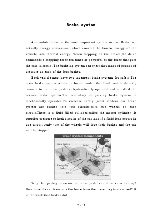
Brake systemAutomobile brake is the most important system in cars.Brake are actually energy conversion ,which convert the kinetic energy of the vehicle into thermal energy .When stepping on the brakes,the drive commands a stopping force ten times as p owerful as the force that puts the cars in motin .The brakeing system can exert thousands of pounds of pressure on each of the four brakes.Each vehicle must have two indenpent brake s ystems for safety.The main brake s ystem which is locate under the hoo d and is directly connect to the brake pedal is hydraulically operated and is called the service brake system.The secondary or parking brake system is mechanically operated.To increase safety ,most modern car brake system are broken into two circuits,with two wheels on each circuit.There is a fluid-filled cylinder,called the master cylinder .It supplies pressure to hoth circuits of the car ,and if a fluid leak occurs in one circuit ,only two of the wheels will lose their brakes and the car will be stopped.Why that pushig down on the brake pedal can slow a car to stop? How dose the car transmits the force from the driver’leg to its wheel? It is the work that brakes did.Layout of Typical Brake system When depressing the breke pedal ,the car transmits the force the drive’s foot to its brakes through a fluid.Since the actual brakes require a much greater force than the drive could apply with his leg ,the car must also multipy the force of the driver’s foot.It dose this in two ways: mechanical advantage a nd hydraulic force multiplication .Leverge The pedal is designed in such a way that it can multiply the force from the driver’s leg several times before any force is even transmitted to the brake fluid.In the figure above ,a force F is being applied t o the left end of the lever.The left end of the lever is twice as long 2X) as the right end (x).Therefore ,on the right end of the lever a force of 2F is available,but it acts through half of the distans (Y) that the left end moves (2Y) .Changing the relat ive lengths of the left and right ends of the lever changes the mulitipliers.Hydraulic Brake Systems The hydraulic system is that force applied at one point is thansmitted to another point using an incompressible fluid , almost alwaays an oil of some so rt .Most brake systems also muitiply the force in the process .The great thing about hydraulic systems is that the pipe connecting the two cylinders can be any length and shape , allowing it to snake through all sorts of things separating the two pistons .The pipe can also fork ,so that one master cylinder can drive more than one salve cylinder if desired .The other neat thing about a hydraulic s ystem is that it makes force multiplicationfairly eas y . In a hydralic system , all you have to do change the si ze of one piston and cylinder to the other .The automobile brake systems are divided into three t ypes of service brake combinations:drum brake , disc brakes and disc-drum combinations.Drum Brake It uses an internal expanding brake shoe with the lining attactet , working within the confines of a rotating brake surface called a brake drum .The brake shoe diameter is expanded to contact the brake surface by a hydraulic cylinder that is referred to as a wheel cylinder . With drum brake , the fluid is forced into the wheel cylinde which pushed the brake shoes out so that the friction lining are pressed againtst the drum , and cause the wheel to stop .Power brakes back in the day , when most cars had drum brakes ,power brakes were not really necessary ---- drum brakes naturally provide some of their own power assist .Since most cars today have disc brakes ,at least on the front wheels , they need power brakes,Without this device ,a lot of drivers would have very tired legs .The brake booster use Vacuum from the engine to multipiy the force that your foot applies to the master cylinder .Disc Brakes Most modern cars have disc brake on the front wheels , and some have disc brakes on all four wheels ,Disc brakes employ a brake disc that rotates with the wheel ,so it is usually referred to as a brake rotor . On a disc brake , the fluid from the master cylinder is forced into a caliper where it presses against a piston ,in—turn , squeezes two brake pads against the disk which is attached to the wheel ,forcing it to slow down or stop .This process is similar to a bicycle brake where two rubber pads rub against the wheel rim creating friction.The most common type of disc brake on modern cars is the single-piston floating caliper.Self-Adjusting brakes The single-piston floating-caliper disc brake is self-centering and self-adjusting .The caliper is able to slide from side to side so it will move to the center each time the brakes are applied .Also,since there is no spring to pull the pads away from the disc ,the pads always stay in light contact with the rotor .This is important because the pistons in the brakes are much larger in diameter than the ones in the master cylinder .If the brake pistons retracted into their cylinders ,it might take several applications of the brake pedal to pump enough fluid into the brake cylinder to engage the brake pads.Self-Adjusting disc brake Older cars had dual or four-pistin fixed-caliper desiger .A piston on each side of the rotor pushed the padon that side .This design has b een largel y eliminated becausesingle-piston designs are cheaper and more reliable .Emergence Brakes In cars with disc brakes on all four wheels ,an emergency brake has to be actuated by a separate mechanism than the primary brakes in case of a total pr imary brake failure .Most cars use a cable to actuate the emergency brake .Some cars with four-wheel disc brakes have a separate drum brake integrated into the hub of the rear wheels .This drum brake is only for the emergency brake sysem ,and it is actuate d only by the cable;it has no hydraulics .Parking Brakes Cars also have the parking brake system .It is used to hold one or more of the vehicle brakes in an applied position for an extended period of time .This brake system must be capable of holding the vehicle on a grade and bringing the vehicie to a stop if the service brakes fail .The parking brake system used on most current model passenger vehicles operates by applying two rear-wheel brakes through a mechanical system of cable and levers.There are air brakes,anti-lock brakes,too .The forme used in heavy trucks and utilizes compressed air as a source of force to stop the truck .The latter used for solving the lockup problem: it can rapidly pump the brakes whenever the system detects a wheel that is locked up .This pumping of the brakes occurs at ten or more times a second ,far fasrer than a human can pump the brake manually.Post-Sale Service and CallbackThe automobile post-sale service means the sale branch provides all the technical service to the customer before or after they buy the car .It may carry on in pre-sale ,or when selling carries on .What but are more is sells after the vehicles ,cerris on the quality guarantee ,the routine maintenance ,the repair ,the technical consultation and the spare parts supply according to the deadline and so on a series of work .In recent years ,the products performances ,product qualities and product prices are almost convergence the same among those famous international automobile compani es .As a result ,the focus of competition in the market focus and transfer to post-sale .Post-sale functions should be enable to use good car products and to create the best returns ,and thus can prove the successful post-sale work .A perfect post-sale service should have two function : to serve both customers and companies themselves .For customers ,the post-sale service could satisfy them and help them solve problems ;for the companies themselves ,it could accurately reflect product utility information ,quality information ,and important social information ,so that the company can make right decisions based on them .Automobile is the most typical product which highl y unifies thesale and the post-sale service .In the intermation market ,one important criterion for automobile sale agent is whethe they have and fulfill post-sale service .When a customer wants to purchase a car ,the first thing he asks is where to repaire the car and whether there are spare-parts .Only getting postive replies ,will he think of other things .Big automobile companies from Eupope ,the US and Japan all recognize that the first car is sold by sales personnel ,but the second car mainly relies on good post-sale service .The automobile is a big product ,so it is very difficult to f ulfill all kinds of post-sale service only depending upon manufaturers .Usually ,a service network undertakes all technical service for manufacturers.In foreign countries ,the post-sale service network is usually linked with sales network .So it can provid e technical service while selling automobile .And the post-sale service network is composed by distributors ,agents and repairing shops .Post-sale service itself belongs to the technical service category.Automobile is hightly technology-intensive ,so the post-sale service includes technical guidance ,technical consultation ,and technical demonstration and so on .Main points which need to be introduced to the society ,dealers ,post-sale service network and customers are completely done by post-sale department .On the other hand ,as a post-sale service man ,one should make sure that you have satisfied your customers when doing your work ,and should make it clear that you want to know if there are any problems with you work ,no matter when they develop .Since you made the project ,you are naturally the best person to service it ,if and when the need arises .Make this clear to your client .Nobody likes callbacks ,and if you’ve done your job well ,you should have few ,if any ,for months or years after the in stallation or delivery.But let the client know that for repairs that result fromordinary use ,you’ll be glad to keep your work looking and working like new---for a modest fee ,of course .If ,however ,problems arise that are clearl y due to shoddy workmanship ,it is incumbent on you to correct them free of charge .This is ,of course ,perhaps the best reason to get it right the first time .There’s no trick to determine whether you are being called back because of a problem due to you workmanship or the clie nt’t use of the unit .Like everything else we’ve covered in this series ,doing right by your customers is just a matter of honesty .Put honesty into practice as part of your selling system and you’ll find that it is the best way to do what is right for you r business ,too .A checklist for maintaining good customer relations:Do anything you can to help the client visualize in advance how the finished project will look .Don’t give ballpark prices unless you already have a well established relationship with the client .Use customers as references ,but only when you are sure they are totally satisfied.Tell customers you want to know if there are problems with your work and that you can provide any routine service .In everything you do ,be honest with your c lient .Automobile callback system originated from the U.S in 1960s .Now it is not new in the U.S.,European countries ,Japan and South Korea .The U.S.has the longest history of automobile callback and the most strict regulations .Until now ,the American gr and has totally recalled more than 200 million vehicles since 1966 ,and more than 24 million tires ,including passenger vehicle ,trucks ,buses ,motorcycles and so on ,And nearly all auto manufactures in the world have recalled cases in the U.S.China’s Fla w Automobile Prosuct Management Stipulation wasimplemented since October1 ,2004 .Automobile is the machine which is assembled by tens of thousands of components and it is not strang to have this kind of flaw or that kind in materials or designs .But most flaws are recessive ,so they will be gradually exposed after using a period of time and people can then realize the flaw’s existence .Sometimes some batch of vehicle components processing ,assembly or material formula change ,and they possibly bring the flaws .The scope of callback s ystem is extremely explicit ,that is the flaw has to be associated with safet y and should appear in the batch .Recall system mainly aims at the systematic and unified flaws which are related with safety and existing in one batch of vehicles .The goal of the automobile recall is to eliminate the flaw and hidden danger ,ensure the public security ,the public benefit and the social economic order .制动系统制动系统是汽车中最重要的系统,它实际上是个能量转换装置,它把动能转化为内能。
车辆工程外文翻译---制动系统
附录1Brake Systems1.Drum vs. DiscBrake technology, just like suspension technology and fuel-system technology, has come a long way in recent years.1)Drum BrakesEarly automotive brake systems, after the era of hand levers of course, used a drum design at all four wheels. They were called drum brakes because the components were housed in a round drum that rotated along with the wheel. Inside was a set of drum that, when the brake pedal was pressed, would force the shoes against the drum and slow the wheel. Fluid was used to transfer the movement of the brake pedal into the movement of the brake shoes, while the drum themselves were made of heat-resistant friction material similar to that used on clutch plates.This basic design proved capable under most circumstances, but it had one major flaw. Under high braking conditions, like descending a steep hill with a heavy load or repeated high-speed slow downs, drum brakes would often fade and lose effectiveness. Usually this fading was the result of too much heat build-up within the shoes. Remember that the principle of braking involves turning kinetic energy (wheelmovement) into thermal energy (heat). For this reason, drum brakes can only operate as long as they can absorb the heat generated by slowing a vehicle's wheels. Once the brake components themselves become saturated with heat, they lose the ability to halt a vehicle, which can be somewhat disconcerting to the vehicle's operator.2) Disc BrakesDisc brakes are used on the front wheels of most cars and on all four wheels onmany cars. A disc rotor is attached to the wheel hub and rotates with the tire and wheel. When the driver applies the brakes, hydraulic pressure from the master cylinder is used to push friction linings against the rotor to stop it.In the disc brake rotor assembly, the rotor is usually made of cast iron. The hub may be manufactured as one piece with the rotor or in two parts. The rotor has a machined braking surface on each face. A splash shield, mounted to the steering knuckle, protects the rotor from road splash.A rotor may be solid or ventilated. Ventilated designs have cooling fins cast between the braking surfaces. This construction considerably increases the cooling area of the rotor casting. Also, when the wheel is in motion, the rotation of these fan-type fins in the rotor provides increased air circulation and more efficient cooling of the brake. Disc brakes do not fade even after rapid, hard brake applications because of the rapid cooling of the rotor.The hydraulic and friction components are housed in a caliper assembly. The caliper assembly straddles the outside diameter of the hub and rotor assembly. When the brakes are applied, the pressure of the pistons is exerted through the shoes in a 'clamping'action on the rotor. Because equal opposed hydraulic pressures are applied to both faces of the rotor throughout application, no distortion of the rotor occurs, regardless of the severity or duration of application. There are many variations of caliper designs, but they can all be grouped into two main categories: moving and stationary caliper. The caliper is fixed in one position on the stationary design. In the moving design, the caliper moves in relation to the rotor.Most late-model cars use the moving caliper design. This design uses a single hydraulic piston and a caliper that can float or slide during application. Floating designs`float'or move on pins or bolts. In sliding designs, the caliper slides sideways on machined surfaces. Both designs work in basically the same way.In the single piston floating caliper, the single-piston caliper assembly is constructed from a single casting that contains one large piston bore in the inboard section of the casting. Inboard refers to the side of the casting nearest the center line of the car when the caliper is mounted. A fluid inlet hole and bleeder valve hole are machined into the inboard section of the caliper and connect directly to the piston bore.The caliper cylinder bore contains a piston and seal. The seal has a rectangular cross section. It is located in a groove that is machined in the cylinder bore. The sealfits around the outside diameter of the piston and provides a hydraulic seal between the piston and the cylinder wall. The rectangular seal provides automatic adjustment of clearance between the rotor and shoe and linings following each application. When the brakes are applied, the caliper seal is deflected by the hydraulic pressure and it inside diameter rides with the piston within the limits of its retention in the cylinder groove. When hydraulic pressure is released, the seal relaxes and returns to its original rectangular shape, retracting the piston into the cylinder enough to provide proper running clearance.As brake linings wear, piston travel tends to exceed the limit of deflection of the seal; the piston therefore slides in the seal to the precise extent necessary to compensate for lining wear.The top of the piston bore is machined to accept a sealing dust boot. The piston in many calipers is steel, precision ground, and nickel chrome plated, giving it a very hard and durable surface. Some manufacturers are using a plastic piston. This is much lighter than steel and provides for a much lighter brake system. The plastic piston insulates well and prevents heat from transferring to the brake fluid. Each caliper contains two shoe and lining assemblies. They are constructed of a stamped metal shoe with the lining riveted or bonded to the shoe and are mounted in the caliper on either side of the rotor. One shoe and lining assembly is called the inboard lining because it fits nearest to the center line of the car. The other is called the outboard shoe and lining assembly.The application and release of the brake pressure actually causes a very slight movement of the piston and caliper. Upon release of the braking effort, the piston and caliper merely relax into a released position. In the released position, the shoes do not retract very far from the rotor surfaces.As the brake lining wears, the piston moves out of the caliper bore and the caliper repositions itself on the mounting bolts an equal distance toward the car. This way, the caliper assembly maintains the inboard and outboard shoe and lining in the same relationship with the rotor surface throughout the full length of the lining.Sliding calipers are made to slide back and forth on the steering knuckle support to which it is mounted. There is a V shaped surface, sometimes called a rail, on the caliper that matches a similar surface on the steering knuckle support. These two mating surfaces allow the caliper to slide in and out. The internal components of the caliper are the same as those previously described.The stationary or fixed caliper has a hydraulic piston on each side of the rotor. Larger calipers may have two pistons on each side of the rotor. The inboard and outboard brake shoes are pushed against the rotor by their own pistons. The caliper is anchored solidly and does not move. The seals around the pistons work just like those already described. The main disadvantage of the stationary caliper is that it has more hydraulic components. This means they are more expensive and have more parts to wear out .2.Other Components in the Hydraulic System:1)Proportioning Valve or Equalizer ValveThese valves are mounted between the master cylinder and the rear wheels. They are designed to adjust the pressure between the front and rear brakes depending on how hard you are st opping. The shorter you stop, the more of the vehicle’s weight is transferred to the front wheels, in some cases, causing the rear to lift and the front to dive. These valves are designed to direct more pressure to the front and less pressure to the rear the harder you stop. This minimizes the chance of premature lockup at the rear wheels.2)Pressure Differential ValveThis valve is usually mounted just below the master cylinder and is responsible for turning the brake warning light on when it detects a malfunction. It measures the pressure from the two sections of the master cylinder and compares them. Since it is mounted ahead of the proportioning or equalizer valve, the two pressures it detects should be equal. If it detects a difference, it means that there is probably a brake fluid leak somewhere in the system.3)Combination ValveThe Combination valve (Figure) is simply a proportioning valve and a pressure differential valve that is combined into one unit.The parking brake (a.k.a.emergency brake ) system controls the rear brakes through a series of steel cables that are connected to either a hand lever or a foot pedal. The idea is that the system is fully mechanical and completely bypasses the hydraulic system so that the vehicle can be brought to a stop even if there is a total brake failure.On drum brakes, the cable pulls on a lever mounted in the rear brake and is directly connected to the brake shoes. This has the effect of bypassing the wheel cylinder and controlling the brakes directly.Disk brakes on the rear wheels add additional complication for parking brakesystems. There are two main designs for adding a mechanical parking brake to rear disk brakes. The first type uses the existing rear wheel caliper and adds a lever attached to a mechanical corkscrew device inside the caliper piston. When the parking brake cable pulls on the lever, this corkscrew device pushes the piston against the pads, thereby bypassing the hydraulic system, to stop the vehicle. This type of system is primarily used with single piston floating calipers, if the caliper is of the four piston fixed type, then that type of system can’t be used. The other system uses a complete mechanical drum brake unit mounted inside the rear rotor. The brake shoes on this system are connected to a lever that is pulled by the parking brake cable to activate the brakes. The brake “drum” is actually the inside part of the rear brake rotor.On cars with automatic transmissions, the parking brake is rarely used. This can cause a couple of problems. The biggest problem is that the brake cables tend to get corroded and eventually seize up causing the parking brake to become inoperative. By using the parking brake from time to time, the cables stay clean and functional. Another problem comes from the fact that the self adjusting mechanism on certain brake systems uses the parking brake actuation to adjust the brakes. If the parking brake is never used, then the brakes never get adjusted.The power brake booster (Figure) is mounted of the firewall directly behind the master cylinder and, along with the master cylinder, is directly connected with the brake pedal. Its purpose is to amplify the available foot pressure applied to the brake pedal so that the amount of foot pressure required to stop even the largest vehicle is minimal. Power for the booster comes from engine vacuum. The automobile engine produces vacuum as a by-product of normal operation and is freely available for use in powering accessories such as the power brake booster. Vacuum enters the booster through a check valve on the booster. The check valve is connected to the engine with a rubber hose and acts as a one-way valve that allows vacuum to enter the booster but dose not let it escape. The booster is an empty shell that is divided into two chambers by a rubber diaphragm. There is a valve in the diaphragm that remains open while foot is off the brake pedal so that vacuum is allowed to fill both chambers. When stepping on the brake pedal, the valve in the diaphragm closes, separating the two chambers and another valve opens to allow air in the chamber on the brake pedal side. This is what provides the power assist. Power boosters are very reliable and cause few problems of their own. However, other things cam contribute to a loss of power assist. In order to have power assist, the engine must be running. If the engine stalls or shutsoff while you are driving, you will have a small reserve of power assist for two or three pedal applications but, after that, the brakes will be extremely hard to apply and you must put as much pressure as you can to bring the vehicle to a stop.The last topic is the Anti-Lock Brakes (ABS). The most efficient braking pressure takes place just before each wheel lock up. When you slam on the brakes in a panic stop and the wheels lock up, causing a screeching sound and leaving strips of rubber on the pavement, you do not stop the vehicle nearly as short as it is capable of stopping. Also, while the wheels are locked up, you loose all steering control so that , if you have an opportunity to steer around the obstacle, you will not be able to do so. Another problem occurs during an extended skid is that you will burn a patch of rubber off the tire which causes a “flat spot” on the tread that will produce an annoying thumping sound as you drive.Anti-lock brake systems solve this lockup problem by rapidly pumping the brakes whenever the system detects a wheel that is locked up. In most cases, only the wheel that is locked will be pumped, while full braking pressure stays available to the other wheels. This effect allows you to stop in the shortest amount of time while maintaining full steering control even if one or more wheels are on ice. The system uses a computer to monitor the speed of each wheel. When it detects that one or more wheels have stopped or are turning much slower than the remaining wheels, the computer sends a signal to momentarily remove and reapply or pulse the pressure to the affected wheels to allow them to continue turning. This “pumping” of the brakes occurs at tem or more times a second, far faster then a human can pump the brakes manually. If you step on the brakes hard enough to engage the anti-lock system, you may feel a strong vibration in the brake pedal. This is a normal condition and indicates that the system is working; however, it can be disconcerting to some people who don’t expect it. If your vehicle has anti-lock brakes, read your owner’s manual to find out more about it.The system consists of am electronic control unit, a hydraulic actuator, and wheel speed sensors at each wheel. If the control unit detects a malfunction in the system, it will illuminate an ABS warming light on the dash to let you know that there is a problem. If there is a problem, the antilock system will not function but the brakes will otherwise function normally.3.Friction materialsBrake shoes and pads are constructed in a similar manner. The pad or shoe iscomposed of a metal backing plate and a friction lining. The lining is either bonded (glued) to the metal, or riveted. Generally, riveted linings provide superior performance, but good quality bonded linings are perfectly adequate.Friction materials will vary between manufacturers and type of pad and the material compound may be referred to as: asbestos, organic, semi-metallic, metallic. The difference between these compounds lies in the types and percentages of friction materials used, material binders and performance modifiers.Generally speaking, organic and non-metallic asbestos compound brakes are quiet, easy on rotors and provide good feel. But this comes at the expense of high temperature operation, so they may not be your best choice for heavy duty use or mountain driving. In most cases, these linings will wear somewhat faster than metallic compound pads, so you will usually replace them more often. But, when using these pads, rotors tend to last longer.Semi-metallic or metallic compound brake linings will vary in performance based on the metallic contents of the compound. Again, generally speaking, the higher the metallic content, the better the friction material will resist heat. This makes them more appropriate for heavy duty applications, but at the expense of braking performance before the pad reaches operating temperature. The first few applications on a cold morning may not give strong braking. Also, metallic and semi-metallic are more likely to squeal. In most cases, metallic compounds last longer than non-metallic pads, but they tend to cause more wear on the rotors. If you use metallic pads, expect to replace the rotors more often.When deciding what type of brake lining is right for you, keep in mind that today's modern cars have brake materials which are matched to the expected vehicle's performance capabilities. Changing the material from OEM specification could adversely affect brake feel or responsiveness. Before changing the brake materials, talk to your dealer or parts supplier to help decide what is most appropriate for your application. Remember that heavy use applications such as towing, stop and go driving, driving down mountain roads, and racing may require a change to a higher performance material.Some more exotic materials are also used in brake linings, among which are Kevlar and carbon compounds. These materials have the capability of extremely good performance for towing, mountain driving or racing. Wear characteristics can be similar to either the metallic or the non-metallic linings, depending on the product youbuy. Most race applications tend to wear like metallic linings, while many of the street applications are more like the non-metallic制动系统1. 刹车:鼓与盘制动技术,就像悬浮技术和燃料系统技术,已走过了漫长的道路1)鼓式制动器早在后时代,手杠杆的汽车制动系统用鼓装在所有的四个车轮。
液压英文文献及翻译
液压英文文献及翻译液压系统1.绪论液压站称液压泵站,是独立的液压装置。
它是按逐级要求供油。
并控制液压油流方向、压力和流量,适用在主机与液压装置可分离的各种液压机械上面。
用户在购后只要将液压站与主机上执行机构(油缸或油马达)用不同的油管相连,液压机械即实现各种规定的动作与工作循环。
液压站是由集成块、泵装置或阀组合、电气盒、油箱电气盒组合而成。
各个部件功能为:泵装置——上装有电机和油泵,其是液压站的动力源,能将机械能转化为液压油压力能。
阀组合--其板式阀装在立板上,板后管连接,与集成块的功能相同。
油集成块--是由液压阀及通道体组装而成。
其对液压油实行压力、方向和流量调节。
箱--是板焊的半封闭容器,上面还装有滤油网、空气滤清器等,是用来储油与油的冷却及过滤。
电气盒--分两种型式:一种是设置外接引线的端子板;一种是配置了全套控制电器。
液压站工作原理:电机带动油泵转动,然后泵从油箱中吸油并供油,将机械能转化为液压站压力能,液压油通过集成块(或阀组合)实现方向、压力、流量调节后经过外接管路并至液压机械里的油缸或油马达中,从而控制液动机方向变换、力量的大小及速度的快慢,来推动各种液压机械做功。
(1)液压的发展历程在我国液压(含液力,下同)、气动和密封件工业的发展历程,大致可分成三个阶段,即:在20世纪50年代初到60年代初是起步阶段;60-70年代为专业化生产体系的成长阶段;80-90年代为快速发展阶段。
在其中,液压工业始于50年代初从机床行业生产的仿苏的磨床、拉床、仿形车床等液压传动来起步,液压元件由机床厂里的液压车间生产,自产自用。
在进入60年代后,液压技术应用从机床逐渐推广到农业机械与工程机械等领域,原来附属于主机厂里的液压车间有些独立出来,成为液压件的专业生产厂。
在60年代末、70年代初,随着生产机械化的不断发展,特别是在为第二汽车制造厂等提供了高效、自动化设备的带动下,液压元件制造业出现了不断迅速发展的局面,一批中小企业也开始成为液压件专业制造厂。
外文翻译--Komatsu先进的液压系统

毕业设计(论文)外文资料翻译学院(系):机械工程学院专业:机械工程及自动化姓名:学号:外文出处:Manufacturing Engineering (用外文写)and Technology-Machining附件: 1.外文资料翻译译文;2.外文原文。
指导教师评语:此翻译文章简单介绍Komatsu先进的液压系统,并详细介绍了先进的液压传动装置,并对计算机控制的自动变速系统进行了详细的描述,翻译用词比较准确,文笔也较为通顺,为在以后工作中接触英文资料打下了基础。
签名:年月日附件1:外文资料翻译译文Komatsu先进的液压系统操作舒适,生产能力大人性化设计的驾驶室——既宽敞又实用。
宽大的有色玻璃窗给操作员极大的视线。
带扶手五挡调节座椅,短行程手摇杆,上位开启前窗和带杠杆的驾驶用的脚踏板,所有这些都起到有助于操作员最大限度地提高产量的作用。
操作噪声低——这完全是因为有先进的OLSS液压系统以及封闭式发动机室和具有橡胶支垫的发动机。
所有这一切都有助于降低驾驶室的噪声。
手控操作杆——使得施工设备的操作轻而易举。
安装在扶手上的手控操作杆最大行程仅为65mm(2.6in),KOMATSU比例压力控制操作系统能减少准确控制施工设备所需的操作强度。
回转制动装置——即使推土机停泊在坡路上也能自动防止液压漂移。
操作员不再需要在施工设备作业的过程中用手握住制动装置。
此外,回转控制装备还配置有封闭式滑阀,以便顺利的启动和停止。
行驶/驾驶控制装置——脚踏板控制装置配有可拆卸的控制杆。
两者可根据实际运用和操作员的偏爱加以选择使用。
支垫机构——在臂缸悬臂首端、铲斗缸和底部卸料缸中,能消减液压缸伸展和收缩引起的震动,从而增加操作的舒适性,延长部件的寿命。
燃耗最低两种模式选择系统,挖掘效率高——模式选择开关可选定泵驱动功率的两种模式:S(标准模式)或(轻负荷模式)。
当需要大功率挖掘时,选择标准模式;当挖掘机用来运送轻材料或平地时,选择轻负载模式。
液压系统外文文献翻译、中英文翻译、外文文献翻译
附录Hydraulic SystemHydraulic presser drive and air pressure drive hydraulic fluid as the transmission is made according to the 17th century, Pascal's principle of hydrostatic pressure to drive the development of an emerging technology, the United Kingdom in 1795 •Barman Joseph (Joseph Barman, 1749-1814), in London water as a medium to form hydraulic press used in industry, the birth of the world's first hydraulic press. Media work in 1905 will be replaced by oil-water and further improved.After the World War I (1914-1918) ,because of the extensive application of hydraulic transmission, especially after 1920, more rapid development. Hydraulic components in the late 19th century about the early 20th century, 20 years, only started to enter the formal phase of industrial production. 1925 Vickers (F. Vickers) the invention of the pressure balanced vane pump, hydraulic components for the modern industrial or hydraulic transmission of the gradual establishment of the foundation. The early 20th century G • Constantia scofluctuations of the energy carried out by passing theoretical and practical research; in 1910 on the hydraulic trans- mission (hydraulic coupling, hydraulic torque converter, etc.) contributions, so that these two areas of development.The Second World War (1941-1945) period, in the United States 30% of machine tool applications in the hydraulic transmission. It should be noted that the development of hydraulic transmission in Japan than Europe and the United States and other countries fornearly 20 years later. Before and after in 1955, the rapid development of Japan's hydraulic drive, set up in 1956, "Hydraulic Industry." Nearly 20 to 30 years, the development of Japan's fast hydraulic transmission, a world leader.Hydraulic transmission There are many outstanding advantages, it is widely used, such as general industrial use of plastics processing machinery, the pressure of machinery, machine tools, etc.; operating machinery engineering machinery, construction machinery, agricultural machinery, automobiles, etc.; iron and steel industry metallurgical machinery, lifting equipment, such as roller adjustment device; civil water projects with flood control and dam gate devices, bed lifts installations, bridges and other manipulation of institutions; speed turbine power plant installations, nuclear power plants, etc.; ship from the deck heavy machinery (winch), the bow doors, bulkhead valve, stern thruster, etc.; special antenna technology giant with control devices, measurement buoys, movements such as rotating stage; military-industrial control devices used in artillery, ship anti- rolling devices, aircraft simulation, aircraft retractable landing gear and rudder control devices and other devices.A complete hydraulic system consists of five parts, namely, power components, the implementation of components, control components, auxiliary components and hydraulic oil.The role of dynamic components of the original motive fluid into mechanical energy to the pressure that the hydraulic system of pumps, it is to power the entire hydraulic system. The structure of the form of hydra- ulic pump gears are generally pump, vane pump and piston pump.Implementation of components (such as hydraulic cylinders and hydraulic motors) which isthe pressure of the liquid can be converted to mechanical energy to drive the load for a straight line reciprocating movement or rotational movement.Control components (that is, the various hydraulic valves) in the hydraulic system to control and regulate the pressure of liquid, flow rate and direction. According to the different control functions, hydraulic pressure control valve can be divided into valves, flow control valves and directional control valve. Pressure control valves are divided into benefits flow valve (safety valve), pressure relief valve, sequence valve, pressure relays, etc.; flow control valves including throttle, adjusting the valves, flow diversion valve sets, etc.; directional control valve includes a one-way valve , one-way fluid control valve, shuttle valve, valve and so on. Under the control of different ways, can be divided into the hydraulic valve control switch valve, control valve and set the value of the ratio control valve.Auxiliary components, including fuel tanks, oil filters, tubing and pipe joints, seals, pressure gauge, oil level, such as oil dollars.Hydraulic oil in the hydraulic system is the work of the energy transfer medium, there are a variety of mineral oil, emulsion oil hydraulic molding Hop categories.The role of the hydraulic system is to help humanity work. Mainly by the implementation of components to rotate or pressure into a reciprocating motion.Hydraulic system and hydraulic power control signal is composed of two parts, the signal control of some parts of the hydraulic power used to drive the control valve movement.Part of the hydraulic power means that the circuit diagram used to show the differentfunctions of the interrelationship between components. Containing the source of hydraulic pump, hydraulic motor and auxiliary components; hydraulic control part contains a variety of control valves, used to control the flow of oil, pressure and direction; operative or hydraulic cylinder with hydraulic motors, according to the actual requirements of their choice.In the analysis and design of the actual task, the general block diagram shows the actual operation of equipment. Hollow arrow indicates the signal flow, while the solid arrows that energy flow.Basic hydraulic circuit of the action sequence - Control components (two four-way valve) and the spring to reset for the implementation of components (double-acting hydraulic cylinder), as well as the extending and retracting the relief valve opened and closed. For the implementation of components and control components, presentations are based on the corresponding circuit diagram symbols, it also introduced ready made circuit diagram symbols.Working principle of the system, you can turn on all circuits to code. If the first implementation of components numbered 0, the control components associated with the identifier is 1. Out with the implementation of components corresponding to the identifier for the even components, then retracting and implementation of components corresponding to the identifier for the odd components. Hydraulic circuit carried out not only to deal with numbers, but also to deal with the actual device ID, in order to detect system failures.DIN ISO1219-2 standard definition of the number of component composition, which includes the following four parts: device ID, circuit ID, component ID and component ID.The entire system if only one device, device number may be omitted.Practice, another way is to code all of the hydraulic system components for numbers at this time, components and component code should be consistent with the list of numbers. This method is particularly applicable to complex hydraulic control system, each control loop are the corresponding number with the systemWith mechanical transmission, electrical transmission compared to the hydraulic drive has the following advantages:1. a variety of hydraulic components can easily and flexibly to layout.2. light weight, small size, small inertia, fast response.3. to facilitate manipulation of control, enabling a wide range of stepless speed regulation (speed range of 2000:1).4. to achieve overload protection automatically.5. the general use of mineral oil as a working medium, the relative motion can be self-lubricating surface, long service life;6. it is easy to achieve linear motion .7. it is easy to achieve the automation of machines, when the joint control of the use of electro-hydraulic, not only can achieve a higher degree of process automation, and remote control can be achieved.The shortcomings of the hydraulic system:1. as a result of the resistance to fluid flow and leakage of the larger, so less efficient. If not handled properly, leakage is not only contaminated sites, but also may cause fire and explosion.2. vulnerable performance as a result of the impact of temperature change, it would be inappropriate in the high or low temperature conditions.3. the manufacture of precision hydraulic components require a higher, more expensive and hence the price.4. due to the leakage of liquid medium and the compressibility and can not be strictly the transmission ratio.5. hydraulic transmission is not easy to find out the reasons for failure; the use and maintenance requirements for a higher level of technology.In the hydraulic system and its system, the sealing device to prevent leakage of the work of media within and outside the dust and the intrusion of foreign bodies. Seals played the role of components, namely seals. Medium will result in leakage of waste, pollution and environmental machinery and even give rise to malfunctioning machinery and equipment for personal accident. Leakage within the hydraulic system will cause a sharp drop in volumetric efficiency, amounting to less than the required pressure, can not even work. Micro-invasive system of dust particles, can cause or exacerbate friction hydraulic component wear, and further lead to leakage.Therefore, seals and sealing device is an important hydraulic equipment components. The reliability of its work and life, is a measure of the hydraulic system an important indicator of good or bad. In addition to the closed space, are the use of seals, so that two adjacent coupling surface of the gap between the need to control the liquid can be sealed following the smallest gap. In the contact seal, pressed into self-seal-style and self-styled self-tight seal (ie, sealed lips) two.The three hydraulic system diseases1. as a result of heat transmission medium (hydraulic oil) in the flow velocity in various parts of the existence of different, resulting in the existence of a liquid within the internal friction of liquids and pipelines at the same time there is friction between the inner wall, which are a result of hydraulic the reasons for the oil temperature. Temperature will lead to increased internal and external leakage, reducing its mechanical efficiency. At the same time as a result of high temperature, hydraulic oil expansion will occur, resulting in increased com- pression, so that action can not be very good control of transmission. Solution: heat is the inherent characteristics of the hydraulic system, not only to minimize eradication. Use a good quality hydraulic oil, hydraulic piping arrangement should be avoided as far as possible the emergence of bend, the use of high-quality pipe and fittings, hydraulic valves, etc.2. the vibration of the vibration of the hydraulic system is also one of its malaise. As a result of hydraulic oil in the pipeline flow of high-speed impact and the control valve to open the closure of the impact of the process are the reasons for the vibration system. Strong vibration control action will cause the system to error, the system will also be some of the more sophisticated equipment error, resulting in system failures. Solutions: hydraulic pipe should be fixed to avoid sharp bends. To avoid frequent changes in flow direction, can not avoid damping measures should be doing a good job. The entire hydraulic system should have a good damping measures, while avoiding the external local oscillator on the system.3. the leakage of the hydraulic system leak into inside and outside the leakage. Leakagerefers to the process with the leak occurred in the system, such as hydraulic piston-cylinder on both sides of the leakage, the control valve spool and valve body, such as between the leakage. Although no internal leakage of hydra- ulic fluid loss, but due to leakage, the control of the established movements may be affected until the cause system failures. Outside means the occurrence of leakage in the system and the leakage between the external environment. Direct leakage of hydraulic oil into the environment, in addition to the system will affect the working environment, not enough pressure will cause the system to trigger a fault. Leakage into the environment of the hydraulic oil was also the danger of fire. Solution: the use of better quality seals to improve the machining accuracy of equipment.Another: the hydraulic system for the three diseases, it was summed up: "fever, with a father拉稀" (This is the summary of the northeast people). Hydraulic system for the lifts, excavators, pumping station, dynamic, crane, and so on large-scale industry, construction, factories, enterprises, as well as elevators, lifting platforms, Deng Axle industry and so on.Hydraulic components will be high-performance, high-quality, high reliability, the system sets the direction of development; to the low power, low noise, vibration, without leakage, as well as pollution control, water-based media applications to adapt to environmental requirements, such as the direction of development; the development of highly integrated high power density, intelligence, macaronis and micro-light mini-hydraulic components; active use of new techniques, new materials and electronics, sensing and other high-tech.---- Hydraulic coupling to high-speed high-power and integrated development of hydraulic transmission equipment, development of water hydraulic coupling medium speedand the field of automotive applications to develop hydraulic reducer, improve product reliability and working hours MTBF; hydraulic torque converter to the development of high-power products, parts and components to improve the manufacturing process technology to improve reliability, promote computer-aided technology, the development of hydraulic torque converter and power shift transmission technology supporting the use of ; Clutch fluid viscosity should increase the quality of products, the formation of bulk to the high-power and high-speed direction.Pneumatic Industry:---- Products to small size, light weight, low power consumption, integrated portfolio of development, the implementation of the various types of components, compact structure, high positioning accuracy of the direction of development; pneumatic components and electronic technology, to the intelligent direction of development; component performance to high-speed, high-frequency, high-response, high-life, high temp- erature, high voltage direction, commonly used oil-free lubrication, application of new technology, new technology and new materials.1. Used high-pressure hydraulic components and the pressure of continuous work to reach 40Mpa, the maximum pressure to achieve instant 48Mpa;2. Diversification of regulation and control;3. To further improve the regulation performance, increase the efficiency of the power train;4. Development and mechanical, hydraulic, power transmission of the composite portfolio adjustment gear;5. Development of energy saving, energy efficient system function;6. To further reduce the noise;7. Application of Hydraulic Cartridge Valves thread technology, compact structure, to reduce the oil spill.液压系统液压传动和气压传动称为流体传动,是根据17世纪帕斯卡提出的液体静压力传动原理而发展起来的一门新兴技术,1795年英国约瑟夫•布拉曼(Joseph Braman,1749-1814),在伦敦用水作为工作介质,以水压机的形式将其应用于工业上,诞生了世界上第一台水压机。
汽车制动系统中英文对照外文翻译文献
汽车制动系统中英文对照外文翻译文献(文档含英文原文和中文翻译)Brake systemsWe all know that pushing down on the brake pedal slows a car to a stop. But how does this happen? How does your car transmit the force from your leg to its wheels? How does it multiply the force so that it is enough to stop something as big as a car?Brake Image GalleryLayout of typical brake system. See more brake images.When you depress your brake pedal, your car transmits the force from your foot to its brakes through a fluid. Since the actual brakes require a much greater force than you could apply with your leg, your car must also multiply the force of your foot. It does this in two ways:∙Mechanical advantage (leverage)∙Hydraulic force multiplicationThe brakes transmit the force to the tires using friction, and the tires transmit that force to the road using friction also. Before we begin our discussion on the components of the brake system, we'll cover these three principles:∙Leverage∙Hydraulics∙FrictionLeverage and HydraulicsIn the figure below, a force F is being applied to the left end of the lever. The left end of the lever is twice as long (2X) as the right end (X). Therefore, on the right end of the lever a force of 2F is available, but it acts through half of the distance (Y) that the left end moves (2Y). Changing the relative lengths of the left and right ends of the lever changes the multipliers.The pedal is designed in such a way that it can multiply the force from yourleg several times before any force is even transmitted to the brake fluid.The basic idea behind any hydraulic system is very simple: Force applied at one point is transmitted to another point using an incompressible fluid, almost always an oil of some sort. Most brake systems also multiply the force in the process. Here you can see the simplest possible hydraulic system:Your browser does not support JavaScript or it is disabled.Simple hydraulic systemIn the figure above, two pistons (shown in red) are fit into two glass cylinders filled with oil (shown in light blue) and connected to one another with an oil-filled pipe. If youapply a downward force to one piston (the left one, in this drawing), then the force is transmitted to the second piston through the oil in the pipe. Since oil is incompressible, the efficiency is very good -- almost all of the applied force appears at the second piston. The great thing about hydraulic systems is that the pipe connecting the two cylinders can be any length and shape, allowing it to snake through all sorts of things separating the twopistons. The pipe can also fork, so that one master cylinder can drive more than one slave cylinder if desired, as shown in here:Your browser does not support JavaScript or it is disabled.Master cylinder with two slavesThe other neat thing about a hydraulic system is that it makes force multiplication (or division) fairly easy. If you have read How a Block and Tackle Works or How Gear Ratios Work, then you know that trading force for distance is very common in mechanical systems. In a hydraulic system, all you have to do is change the size of one piston and cylinder relative to the other, as shown here:Your browser does not support JavaScript or it is disabled.Hydraulic multiplicationTo determine the multiplication factor in the figure above, start by looking at the size of the pistons. Assume that the piston on the left is 2 inches (5.08 cm) in diameter (1-inch / 2.54 cm radius), while the piston on the right is 6 inches (15.24 cm) in diameter (3-inch / 7.62 cm radius). The area of the two pistons is Pi * r2. The area of the left piston is therefore 3.14, while the area of the piston on the right is 28.26. The piston on the right is nine times larger than the piston on the left. This means that any force applied to theleft-hand piston will come out nine times greater on the right-hand piston. So, if you apply a 100-pound downward force to the left piston, a 900-pound upward force will appear on the right. The only catch is that you will have to depress the left piston 9 inches (22.86 cm) to raise the right piston 1 inch (2.54 cm).A Simple Brake SystemBefore we get into all the parts of an actual car brake system, let's look at a simplified system:Your browser does not support JavaScript or it is disabled.A simple brake systemYou can see that the distance from the pedal to the pivot is four times the distance from the cylinder to the pivot, so the force at the pedal will be increased by a factor of four before it is transmitted to the cylinder.You can also see that the diameter of the brake cylinder is three times the diameter of the pedal cylinder. This further multiplies the force by nine. All together, this system increases the force of your foot by a factor of 36. If you put 10 pounds of force on the pedal, 360 pounds (162 kg) will be generated at the wheel squeezing the brake pads.There are a couple of problems with this simple system. What if we have a leak? If it is a slow leak, eventually there will not be enough fluid left to fill the brake cylinder, and the brakes will not function. If it is a major leak, then the first time you apply the brakes all of the fluid will squirt out the leak and you will have complete brake failure.Drum brakes work on the same principle as disc brakes: Shoes press against a spinning surface. In this system, that surface is called a drum.Figure 1. Location of drum brakes. See more drum brakepictures.Many cars have drum brakes on the rear wheels and disc brakes on the front. Drum brakes have more parts than disc brakes and are harder to service, but they are less expensive to manufacture, and they easily incorporate an emergency brake mechanism.In this edition of HowStuffWorks, we will learn exactly how a drum brake system works, examine the emergency brake setup and find out what kind of servicing drum brakes need.Figure 2. Drum brake with drum in placeFigure 3. Drum brake without drum in placeLet's start with the basics.The Drum BrakeThe drum brake may look complicated, and it can be pretty intimidating when you open one up. Let's break it down and explain what each piece does.Figure 4. Parts of a drum brakeLike the disc brake, the drum brake has two brake shoes and a piston. But the drum brake also has an adjuster mechanism, an emergency brake mechanism and lots of springs.First, the basics: Figure 5 shows only the parts that provide stopping power.Your browser does not support JavaScript or it is disabled.Figure 5. Drum brake in operationWhen you hit the brake pedal, the piston pushes the brake shoes against the drum. That's pretty straightforward, but why do we need all of those springs?This is where it gets a little more complicated. Many drum brakes are self-actuating. Figure 5 shows that as the brake shoes contact the drum, there is a kind of wedging action, which has the effect of pressing the shoes into the drum with more force.The extra braking force provided by the wedging action allows drum brakes to use a smaller piston than disc brakes. But, because of the wedging action, the shoes must be pulled away from the drum when the brakes are released. This is the reason for some of the springs. Other springs help hold the brake shoes in place and return the adjuster arm after it actuates.Brake AdjusterFor the drum brakes to function correctly, the brake shoes must remain close to the drum without touching it. If they get too far away from the drum (as the shoes wear down, for instance), the piston will require more fluid to travel that distance, and your brake pedal will sink closer to the floor when you apply the brakes. This is why most drum brakes have an automatic adjuster.Figure 6. Adjuster mechanismNow let's add in the parts of the adjuster mechanism. The adjuster uses theself-actuation principle we discussed above.Your browser does not support JavaScript or it is disabled.Figure 7. Drum brake adjuster in operationIn Figure 7, you can see that as the pad wears down, more space will form between the shoe and the drum. Each time the car stops while in reverse, the shoe is pulled tight against the drum. When the gap gets big enough, the adjusting lever rocks enough to advance the adjuster gear by one tooth. The adjuster has threads on it, like a bolt, so that it unscrews a little bit when it turns, lengthening to fill in the gap. When the brake shoes wear a little more, the adjuster can advance again, so it always keeps the shoes close to the drum.Some cars have an adjuster that is actuated when the emergency brake is applied. This type of adjuster can come out of adjustment if the emergency brake is not used forlong periods of time. So if you have this type of adjuster, you should apply your emergency brake at least once a week.ServicingThe most common service required for drum brakes is changing the brake shoes. Some drum brakes provide an inspection hole on the back side, where you can see how much material is left on the shoe. Brake shoes should be replaced when the friction material has worn down to within 1/32 inch (0.8 mm) of the rivets. If the friction material is bonded to the backing plate (no rivets), then the shoes should be replaced when they have only 1/16 inch (1.6 mm) of material left.Photo courtesy of a local AutoZone storeFigure 9. Brake shoeJust as in disc brakes, deep scores sometimes get worn into brake drums. If aworn-out brake shoe is used for too long, the rivets that hold the friction material to the backing can wear grooves into the drum. A badly scored drum can sometimes be repaired by refinishing. Where disc brakes have a minimum allowable thickness, drum brakes have a maximum allowable diameter. Since the contact surface is the inside of the drum, as you remove material from the drum brake the diameter gets bigger.Figure 10. Brake drum制动系统众所周知,踩下制动踏板可以使汽车减速至停止。
液压系统外文文献翻译中英文

外文文献翻译(含:英文原文及中文译文)英文原文Hydraulic systemW Arnold1 IntroductionThe hydraulic station is called a hydraulic pump station and is an independent hydraulic device. It is step by step to supply oil. And control the direction of hydraulic oil flow, pressure and flow, suitable for the host and hydraulic equipment can be separated on the various hydraulic machinery.After the purchase, the user only needs to connect the hydraulic station and the actuator (hydraulic or oil motor) on the mainframe with different tubings. The hydraulic machine can realize various specified actions and working cycles.The hydraulic station is a combination of manifolds, pump units or valve assemblies, electrical boxes, and tank electrical boxes. Each part function is:The pump unit is equipped with a motor and an oil pump, which is the power source of the hydraulic station and can convert mechanical energy into hydraulic oil pressure energy.V alve combination - its plate valve is mounted on the vertical plate, and the rear plate is connected with the same function as the manifold.Oil manifolds - assembled from hydraulic valves and channel bodies. It regulates hydraulic oil pressure, direction and flow.Box--a semi-closed container for plate welding. It is also equipped with an oil screen, an air filter, etc., which is used for cooling and filtering of oil and oil.Electrical box - divided into two types: one is to set the external lead terminal board; one is equipped with a full set of control appliances.The working principle of the hydraulic station: The motor drives the oil pump to rotate, then the pump sucks oil from the oil tank and supplies oil, converts the mechanical energy into hydraulic pressure energy, and the hydraulic oil passes through the manifold (or valve assembly) to adjust the direction, pressure and flow and then passes through the external tube. The way to the hydraulic cylinder or oil motor in the hydraulic machinery, so as to control the direction of the hydraulic motor, the strength of the speed and speed, to promote all kinds of hydraulic machinery to do work.(1) Development history of hydraulic pressureThe development history of hydraulics (including hydraulic power, the same below), pneumatics, and seals industry in China can be roughly divided into three stages, namely: the starting stage in the early 1950s to the early 60s; and the professional in the 60s and 70s. The growth stage of the production system; the 80-90's is a stage of rapid development. Among them, the hydraulic industry began in the early 1950s with thedevelopment of hydraulic machines such as Grinding Machines, broaching machines, and profiling lathes, which were produced by the machine tool industry. The hydraulic components were produced by the hydraulic workshop in the machine tool factory, and were produced for self use. After entering the 1960s, the application of hydraulic technology was gradually promoted from the machine tool to the agricultural machinery and engineering machinery. The original hydraulic workshop attached to the main engine plant was independent and became a professional manufacturer of hydraulic components. In the late 1960s and early 1970s, with the continuous development of mechanization of production, particularly in the provision of highly efficient and automated equipment for the second automobile manufacturing plant, the hydraulic component manufacturing industry witnessed rapid development. The batch of small and medium-sized enterprises also began to become specialized manufacturers of hydraulic parts. In 1968, the annual output of hydraulic components in China was close to 200,000 pieces. In 1973, in the fields of machine tools, agricultural machinery, construction machinery and other industries, the professional factory for the production of hydraulic parts has grown to over 100, and its annual output exceeds 1 million pieces. Such an independent hydraulic component manufacturing industry has taken shape. At this time, the hydraulic product has evolved from the original imitation Su product intoa combination of imported technology and self-designed products. The pressure has been developed towards medium and high pressures, and electro-hydraulic servo valves and systems have been developed. The application of hydraulics has been further expanded. The pneumatic industry started a few years later than hydraulics, and it was only in 1967 that it began to establish a professional pneumatic components factory. Pneumatic components began to be manufactured and sold as commodities. Its sealing industry including rubber seals, flexible graphite seals, and mechanical seals started from the production of common O-rings, oil seals, and other extruded rubber seals and asbestos seal products in the early 1950s. In the early 1960s, it began to develop and produce flexible products. Graphite seals and mechanical seals and other products. In the 1970s, a batch of batches of professional production plants began to be established one after another in the systems of the former Ministry of Combustion, the Ministry of Agriculture, and the Ministry of Agricultural Machinery, formally forming the industry, which laid the foundation for the development of the seal industry.In the 1980s, under the guidance of the national policy of reform and opening up, with the continuous development of the machinery industry, the contradiction between the basic components lags behind the host computer has become increasingly prominent and caused the attention of all relevant departments. To this end, the former Ministry of Machinesestablished the General Infrastructure Industry Bureau in 1982, and unified the original pneumatic, hydraulic, and seal specialties that were scattered in the industries of machine tools, agricultural machinery, and construction machinery, etc. The management of a piece of office, so that the industry in the planning, investment, the introduction of technology and scientific research and development and other aspects of the basic parts of the bureau's guidance and support. This has entered a period of rapid development, it has introduced more than 60 foreign advanced technology, of which more than 40 hydraulic, pneumatic 7, after digestion and absorption and technological transformation, are now mass production, and has become the industry's leading products . In recent years, the industry has intensified its technological transformation. From 1991 to 1998, the total investment of national, local, and corporate self-raised funds totaled about 2 billion yuan, of which more than 1.6 billion were hydraulic. After continuous technological transformation and technological breakthroughs, the technical level of a group of major enterprises has been further improved, and technological equipment has also been greatly improved, laying a good foundation for forming a high starting point, specialization, and mass production. In recent years, under the guidance of the principle of common development of multiple ownership systems in the country, various small and medium-sized enterprises with different ownership have rapidly emerged and haveshown great vitality. With the further opening up of the country, foreign-funded enterprises have developed rapidly, which plays an important role in raising industry standards and expanding exports. So far China has established joint ventures with famous manufacturers in the United States, Germany, Japan and other countries or directly established piston pumps/motors, planetary speed reducers, hydraulic control valves, steering gears, hydraulic systems, hydrostatic transmissions, and hydraulic components. The company has more than 50 manufacturing enterprises such as castings, pneumatic control valves, cylinders, gas processing triplets, rubber seals, and mechanical seals, and has attracted more than 200 million U.S. dollars in foreign capital.(2) Current statusBasic profileAfter more than 40 years of hard work, China's hydraulics, pneumatics and seals industry has formed a complete industrial system with a certain level of production capacity and technical level. According to the statistics of the third n ational industrial census in 1995, China’s state-owned, privately-owned, cooperative, village-run, individual, and “funded enterprises” have annual sales income of more than 1 million yuan in hydraulic, pneumatic, and seal industrial townships and above. There are a total of more than 1,300 companies, including about 700 hydraulics, and about 300 pneumatic and sealing parts. According to thestatistics of the international industry in 1996, the total output value of the hydraulic industry in China was about 2.448 billion yuan, accounting for the 6th in the world; the total output value of the pneumatic industry was about 419 million yuan, accounting for the world’s10 people.2. Current supply and demand profileWith the introduction of technology, independent development and technological transformation, the technical level of the first batch of high-pressure plunger pumps, vane pumps, gear pumps, general hydraulic valves, oil cylinders, oil-free pneumatic components and various types of seals has become remarkable. Improve, and can be stable mass production, provide guarantees for all types of host to improve product quality. In addition, certain achievements have also been made in the aspects of CAD, pollution control, and proportional servo technology for hydraulic pneumatic components and systems, and have been used for production. So far, the hydraulic, pneumatic and seal products have a total of about 3,000 varieties and more than 23,000 specifications. Among them, there are about 1,200 types of hydraulic pressure, more than 10,000 specifications (including 60 types of hydrodynamic products, 500 specifications); about 1350 types of pneumatic, more than 8,000 specifications; there are also 350 types of rubber seals, more than 5000 The specifications are now basically able to adapt to the general needs ofvarious types of mainframe products. The matching rate for major equipment sets can reach more than 60%, and a small amount of exports has started.In 1998, the domestic production of hydraulic components was 4.8 million pieces, with sales of about 2.8 billion yuan (of which mechanical systems accounted for 70%); output of pneumatic components was 3.6 million pieces, and sales were about 550 million yuan (including mechanical systems accounting for about 60%) The production of seals is about 800 million pieces, and the sales volume is about 1 billion yuan (including about 50% of mechanical systems). According to the statistics of the annual report of the China Hydraulic and Pneumatic Sealing Industry Association in 1998, the production and sales rate of hydraulic products was 97.5% (101% of hydraulic power), 95.9% of air pressure, and 98.7% of seal. This fully reflects the basic convergence of production and sales.Although China's hydraulic, pneumatic and sealing industries have made great progress, there are still many gaps compared with the development needs of the mainframe and the world's advanced level, which are mainly reflected in the variety, performance and reliability of products. . Take hydraulic products as an example, the product varieties are only 1/3 of the foreign country, and the life expectancy is 1/2 of that of foreign countries. In order to meet the needs of key hosts, imported hosts, and majortechnical equipment, China has a large number of imported hydraulic, pneumatic, and sealing products every year. According to customs statistics and relevant data analysis, in 1998, the import volume of hydraulic, pneumatic and seal products was about 200 million U.S. dollars, of which the hydraulic pressure was about 140 million U.S. dollars, the pneumatics were 30 million U.S. dollars, and the seal was about 0.3 billion U.S. dollars. The year is slightly lower. In terms of amount, the current domestic market share of imported products is about 30%. In 1998, the total demand for hydraulic parts in the domestic market was about 6 million pieces, and the total sales volume was 4 billion yuan; the total demand for pneumatic parts was about 5 million pieces, and the total sales volume was over 700 million yuan; the total demand for seals was about 1.1 billion yuan. Pieces, total sales of about 1.3 billion yuan. (3) Future developments1. The main factors affecting development(1) The company's product development capability is not strong, and the level and speed of technology development can not fully meet the current needs for advanced mainframe products, major technical equipment and imported equipment and maintenance;(2) Many companies have lagged behind in manufacturing process, equipment level and management level, and their sense of quality is not strong, resulting in low level of product performance, unstable quality,poor reliability, and insufficiency of service, and lack of user satisfaction. And trusted branded products;(3) The degree of professional specialization in the industry is low, the power is scattered, the duplication of the low level is serious, the product convergence between the region and the enterprise leads to blind competition, and the prices are reduced each other, thus the efficiency of the enterprise is reduced, the funds are lacking, and the turnover is difficult. Insufficient investment in development and technological transformation has severely restricted the overall level of the industry and its competitive strength.(4) When the degree of internationalization of the domestic market is increasing, foreign companies have gradually entered the Chinese market to participate in competition, coupled with the rise of domestic private, cooperative, foreign-funded, and individual enterprises, resulting in increasing impact on state-owned enterprises. .2. Development trendWith the continuous deepening of the socialist market economy, the relationship between supply and demand in the hydraulic, pneumatic and sealed products has undergone major changes. The seller market characterized by “shortage” has basically become a buyer’s market characterized by “structured surplus”. Replaced by. From the perspective of overall capacity, it is already in a trend of oversupply, and in particular,general low-grade hydraulic, pneumatic and seals are generally oversupply; and like high-tech products with high technological content and high value and high value-added products that are urgently needed by the host, Can not meet the needs of the market, can only rely on imports. After China's entry into the WTO, its impact may be greater. Therefore, during the “10th Five-Y ear Plan” period, the growth of the industry’s output value must not only rely on the growth of quantity. Instead, it should focus on the structural contradiction of the industry and intensify efforts to adjust the industrial structure and product structure. It should be based on the improvement of quality. Product technology upgrades in order to adapt to and stimulate market demand, and seek greater development.2. Hydraulic application on power slide(1) Introduction of Power Sliding TableUsing the binding force curve diagram and the state space analysis method to analyze and study the sliding effect and the smoothness of the sliding table of the combined machine tool, the dynamics of the hydraulic drive system of the sliding table—the self-regulating back pressure regulating system are established. mathematical model. Through the digital simulation system of the computer, the causes and main influencing factors of the slide impact and the motion instability are analyzed. What kind of conclusions can be drawn from those, if we canreasonably design the structural dimensions of hydraulic cylinders and self-regulating back pressure regulators ——The symbols used in the text are as follows:s 1 - flow source, that is, the flow rate of the governor valve outlet;S el —— sliding friction of the sliding table;R - the equivalent viscous friction coefficient of the slide;I 1 - quality of slides and cylinders;12 - self-adjusting back pressure valve core quality;C 1, c 2 - liquid volume without cylinder chamber and rod chamber;C 2 - Self-adjusting back pressure valve spring compliance;R 1, R2 - Self-adjusting back pressure valve damping orifice fluid resistance;R 9 - Self-adjusting back pressure valve valve fluid resistance;S e2——initial pre-tightening force of self-adjusting back pressure valve spring;I 4, I5 - Equivalent liquid sense of the pipeline;C 5, C 6 - equivalent liquid capacity of the pipeline;R 5, R7 - Equivalent liquid resistance of the pipeline;V 3, V4 - cylinder rodless cavity and rod cavity volume;P 3, P4—pressure of the rodless cavity and rod cavity of the cylinder;F - the slide bears the load;V - speed of slide motion;In this paper, the power bond diagram and the state space splitting method are used to establish the system's motion mathematical model, and the dynamic characteristics of the slide table can be significantly improved.In the normal operation of the combined machine tool, the magnitude of the speed of the slide, its direction and the load changes it undergoes will affect its performance in varying degrees. Especially in the process of work-in-process, the unsteady movement caused by the advancing of the load on the slide table and the cyclical change of the load will affect the surface quality of the workpiece to be machined. In severe cases, the tool will break. According to the requirements of the Dalian Machine Tool Plant, the author used the binding force curve diagram and the state space analysis method to establish a dynamic mathematical model of a self-adjusting back pressure and speed adjustment system for the new hydraulic drive system of the combined machine tool slide. In order to improve the dynamic characteristics of the sliding table, it is necessary to analyze the causes and main influencing factors of the impetus and movement of the sliding table. However, it must pass the computer's digital simulation and the final results obtained from the research.(2) Dynamic Mathematical ModelThe working principle diagram of the self-adjusting back pressure speedregulation system of the combined machine tool slide hydraulic drive system is shown in the figure. This system is used to complete the work-cycle-stop-rewind. When the sliding table is working, the three-position four-way reversing valve is in the illustrated position. The oil supply pressure of the oil pump will remain approximately constant under the effective action of the overflow valve, and the oil flow passes through the reversing valve and adjusts the speed. The valve enters the rodless chamber of the cylinder to push the slide forward. At the same time, the pressurized oil discharged from the rod chamber of the cylinder will flow back to the tank through the self-regulating back pressure valve and the reversing valve. During this process, there was no change in the operating status of both the one-way valve and the relief valve. The complex and nonlinear system of the hydraulic drive system of the self-adjusting back pressure governor system is a kind of self-adjusting back-pressure governor system. To facilitate the study of its dynamic characteristics, a simple and reasonable dynamic mathematical model that only considers the main influencing factors is established. Especially important [1][2]. From the theoretical analysis and the experimental study, we can see that the system process time is much longer than the process time of the speed control valve. When the effective pressure bearing area of the rodless cavity of the fuel tank is large, the flow rate at the outlet of the speed control valve is instantaneous. The overshoot is reflected in thesmall change in speed of the slide motion [2]. In order to further broaden and deeply study the dynamic characteristics of the system so that the research work can be effectively performed on a miniature computer, this article will further simplify the original model [2], assuming that the speed control valve is output during the entire system pass. When the flow is constant, this is considered to be the source of the flow. The schematic diagram of the dynamic model structure of this system is shown in Fig. 2. It consists of a cylinder, a sliding table, a self-adjusting back pressure valve, and a connecting pipe.The power bond graph is a power flow graph. It is based on the transmission mode of the system energy, based on the actual structure, and uses the centralized parameters to represent the role of the subsystems abstractly as a resistive element R, a perceptual element I, and a capacitive element. Three kinds of role of C. Using this method, the physical concept of modeling is clear, and combined with the state-space analysis method, the linear system can be described and analyzed more accurately. This method is an effective method to study the dynamic characteristics of complex nonlinear systems in the time domain. According to the main characteristics of each component of the self-adjusting back pressure control system and the modeling rules [1], the power bond diagram of the system is obtained. The upper half of each key in the figure represents the power flow. The two variables that makeup the power are the force variables (oil pressure P and force F) and the flow variables (flow q and velocity v). The O node indicates that the system is connected in parallel, and the force variables on each key are equal and the sum of the flow variables is zero; 1 The nodes represent the series connection in the system, the flow variables on each key are equal and the sum of the force variables is Zero. TF denotes a transformer between different energy forms. The TF subscripted letter represents the conversion ratio of the flow variable or the force variable. The short bar on the key indicates the causal relationship between the two variables on the key. The full arrow indicates the control relationship. There are integral or differential relationships between the force and flow variables of the capacitive and perceptual elements in the three types of action elements. Therefore, a complex nonlinear equation of state with nine state variables can be derived from Fig. 3 . In this paper, the research on the dynamic characteristics of the sliding table starts from the two aspects of the slide's hedging and the smoothness of the motion. The fourth-order fixed-length Runge-Kutta is used for digital simulation on the IBM-PC microcomputer.(3) Slide advanceThe swaying phenomenon of the slide table is caused by the sudden disappearance of the load acting on the slide table (such as drilling work conditions). In this process, the table load F, the moving speed V, and thepressure in the two chambers of the cylinder P3 and P4 can be seen from the simulation results in Fig. 4. When the sliding table moves at a uniform speed under the load, the oil pressure in the rodless cavity of the oil cylinder is high, and a large amount of energy is accumulated in the oil. When the load suddenly disappears, the oil pressure of the cavity is rapidly reduced, and the oil is rapidly reduced. When the high-pressure state is transferred to the low-pressure state, a lot of energy is released to the system, resulting in a high-speed forward impact of the slide. However, the front slide of the sliding table causes the pressure in the rod cavity of the oil cylinder to cause the back pressure to rise, thereby consuming part of the energy in the system, which has a certain effect on the kicking of the slide table. We should see that in the studied system, the inlet pressure of the self-adjusting back pressure valve is subject to the comprehensive effect of the two-chamber oil pressure of the oil cylinder. When the load suddenly disappears, the pressure of the self-adjusting back pressure valve rapidly rises and stably exceeds the initial back pressure value. It can be seen from the figure that self-adjusting back pressure in the speed control system when the load disappears, the back pressure of the cylinder rises more than the traditional speed control system, so the oil in the rod cavity of the cylinder absorbs more energy, resulting in the amount of forward momentum of the slide It will be about 20% smaller than traditionalspeed control systems. It can be seen from this that the use of self-adjusting back-gear speed control system as a drive system slider has good characteristics in suppressing the forward punch, in which the self-adjusting back pressure valve plays a very large role.(4) The smoothness of the slideWhen the load acting on the slide changes periodically (such as in the case of milling), the speed of the slide will have to fluctuate. In order to ensure the processing quality requirements, it must reduce its speed fluctuation range as much as possible. From the perspective of the convenience of the discussion of the problem, assume that the load changes according to a sine wave law, and the resulting digital simulation results are shown in Figure 5. From this we can see that this system has the same variation rules and very close numerical values as the conventional speed control system. The reason is that when the change of the load is not large, the pressure in the two chambers of the fuel tank will not have a large change, which will eventually lead to the self-regulating back pressure valve not showing its effect clearly.(5) Improvement measuresThe results of the research show that the dynamic performance of a sliding table with self-regulating back pressure control system as a drive system is better than that of a traditional speed control system. To reduce the amount of kick in the slide, it is necessary to rapidly increase the backpressure of the rod cavity when the load disappears. To increase the smoothness of the sliding table, it is necessary to increase the rigidity of the system. The main measure is to reduce the volume of oil. From the system structure, it is known that the cylinder has a large volume between the rod cavity and the oil discharge pipe, as shown in Fig. 6a. Its existence in terms of delay and attenuation of the self-regulating back pressure valve function, on the other hand, also reduces the rigidity of the system, it will limit the further improvement of the propulsion characteristics and the smoothness of the motion. Thus, improving the dynamic characteristics of the sliding table can be handled by two methods: changing the cylinder volume or changing the size of the self-regulating back pressure valve. Through the simulation calculation of the structural parameters of the system and the comparison of the results, it can be concluded that the ratio of the volume V4 between the rod cavity and the oil discharge pipe to the volume V3 between the rodless cavity and the oil inlet pipe is changed from 5.5 to 5.5. At 1 oclock, as shown in the figure, the diameter of the bottom end of the self-adjusting back pressure valve is increased from the original 10mm to 13mm, and the length of the damper triangle groove is reduced from the original lmm to 0.7mm, which will enable the front of the slide table. The impulse is reduced by 30%, the transition time is obviously shortened, and the smoothness of the slide motion will also be greatly improved.中文译文液压系统W Arnold1. 绪论液压站称液压泵站,是独立的液压装置。
- 1、下载文档前请自行甄别文档内容的完整性,平台不提供额外的编辑、内容补充、找答案等附加服务。
- 2、"仅部分预览"的文档,不可在线预览部分如存在完整性等问题,可反馈申请退款(可完整预览的文档不适用该条件!)。
- 3、如文档侵犯您的权益,请联系客服反馈,我们会尽快为您处理(人工客服工作时间:9:00-18:30)。
附录AHydraulic Brake SystemsWhen you step on the brake pedal,you expect the vehicle to stop.The brake pedal operates a hydraulic that is used for two reasons.First,fluid under pressure can be carried to all parts of the vehicle by small hoses or metal lines without taking up a lot of room of causing routing problems.Second,the hydraulic fluid offers a great mechanical advantage-little foot pressure is required on the pedal,but a great deal of pressure is generated at the wheels.The brake pedal is linked to a piston in the brake master cylinder containing a small piston and a fluid reservoir.Modern master cylinders are actually two separate cylinders.Such a system is called a dual circuit,because the front cylinder is connected to the front brakes and the rear cylinder to the rear brakes.(Some vehicles are connected diagonally).The two cylinders are actually separated,allowing for emergency stopping power should one part of the system fail.The entire hydraulic system from the master cylinder to the wheels is full of hydraulic brake fluid.When the brake pedal is depressed,the piston in the master cylinder are forced to move,exerting tremendous force on the fluid in the lines.The fluid has nowhere to go,and forces the wheel cylinder pistons(drum brakes) orcaliper pistons(disc brakes) to exert pressure on the brake shoes or pads.The friction between the brake shoe and wheel drum or the brake pad and rotor (disc) slows the vehiche and eventually stops it.Also attached to the brake pedal si a switch that lights the brake lights as the pedal is depressed.The lights stay on until the brake pedal is released and returns to its normal position.Each wheel cylinder in a drum brake system contains two pistons,one at either end,which push outward in opposite directions.In disc brake systems,the wheel cylinders are part of the caliper (there can be as many as four or as few as one ).Whether disc or drum type,all pistons use some type of rubber seal to prevent leakage around thepiston,and a rubber dust boot seals the outer of the wheel cylinders against dirt and moisture.When the brake pedal is released,a spring pushes the master cylinder pistons back to their normal positions.Check valves in the master cylinder piston allow fluid to flow toward the wheel cylinders or calipers as the piston returns.Then as the brake shoe return springs pull the brake shoes back to the released position,excess fluid returns to the master cylinder through compensating ports,which have been uncovered as the pistons move back.Any fluid that has leaked from the system will also be replaced through the compensating ports.All dual circuit brake systems use a switch to activate a light,warning of brake failure.The switch si located in a valve mounted near the master cylinder.A piston in the valve reveives pressure on each end from the front and rear brake circuits.When the pressures are balanced,the piston remains stationary,but when one circuit has a leak,greater pressure during the application of the brakes will force the piston to one side or the other,closing the switch and activating the warning light.The light can also be activated by the ignition switch during engine starting or by the parking brake.Front disc,rear drum brake systems also have a metering valve to prevent the front disc brakes from engaging before the rear brakes have contacted the drums.This ensures that the front brakes will not normally be used alone to stop the vehicle.A proportioning valve is also used to limit pressure to the rear brakes to prevent rear wheel lock-up during hard braking.Brake shoes and pads are constructed in a similar.The pad or shoe is composed of a metal backing plate and a priction lining.The lining is either bonded(glued) to the metal,or riveted.Generally,riveted linings provide superior performance,but good quality bonded linings are perfectly adequate.Friction materials will vary between manufacturers and type of pad and the material compound may be referred to as asbestos,organic,semi-metallic,metallic.The difference between these compounds lies in the types and percentages of friction materials used,material binders and performance modifiers.Generally speaking,organic and non-metallic asbestos compound brakes are quiet,easy on rotors and provide good feel.But this comes at the expense of high temperature operation,so they may not be your best choice for heavy duty use or mountiandriving.In most cases,these linings will wear somewhat faster than metallic compound pads,so you will usually replace them more often.But,when using these pads,rotors tend to last longer.Semi-metallic or metallic compound brake linings will vary in performance based on the metallic contents of the compound.Again,generally speaking,the higher the metallic content,the better the friction material will resist heat.This makes them more appropriate for heavy duty applications,but at the expense of braking performance before the pad reaches operating temperature.The first few applications on a cold morning may not give strong braking.Also,metallics and semi-metallics are more likely to squeal,In most cases,metallic compounds last longer than non-metallic pads,but they tend to cause more wear on the rotors.If you use metallic pads,expect to replace the rotors more often.When deciding what type of brake lining is right for you,keep in mind that today’s modern cars have brake materials which are matched to the expected vehicle’s performance capabilities.Changing the material from OEM specification could adversely addect brake feel or responsiveness.Before changing the brake materials,talk to your deaker or parts supplier to help decide what is most appropriate for your application. Remenber that use applications such as towing,stop and go driving,driving down mountain roads,and racing may require a change to a higher performance material.Some more exotic materials are also used in brake linings,among which are Kevlar and carbon compounds.These materials have the capability of extremely good performance for towing,mountain driving or racing.Wear characteristics can be similar to either applications tend to wear like metallic linings,while many of the streetapplications aremore like the non-metallics.附录B液压制动系统当踩下制动踏板,您希望该车辆停下。