往复泵外文翻译--压缩机,泵,制冷工程
化工设备常用词汇中英文对照
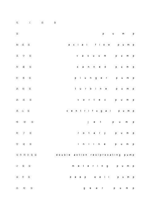
化工设备泵p u m p 轴流泵a x i a l f l o w p u m p 真空泵v a c u u m p u m p 屏蔽泵c a n n e d p u m p 柱塞泵p l u n g e r p u m p 涡轮泵t u r b i n e p u m p 涡流泵v o r t e x p u m p 离心泵c e n t r i f u g a l p u m p 喷射泵j e t p u m p 转子泵r o t a r y p u m p 管道泵i n l i n e p u m p 双作用往复泵d o u b l e a c t i o n r e c i p r o c a t i n g p u m p 计量泵m e t e r i n g p u m p 深井泵d e e p w e l l p u m p 齿轮泵g e a r p u m p手摇泵h a n d(w o b b l e)p u m p 螺杆泵s c r e w(s p i r a l)p u m p 潜水泵s u b m e r s i b l e p u m p 斜转子泵i n c l i n e d r o t o r p u m p 封闭式电磁泵h e r m e t i c a l l y s e a l e d m a g n e t i c d r i v e p u m p 气升泵a i r-l i f t-p u m p 轴承b e a r i n g 叶轮i m p e l l e r 虹吸管s i p h o n 高压容器h i g h p r e s s u r e v e s s e l 焚化炉i n c i n e r a t o r 火焰清除器f l a m e a r r e s t e r 工业炉f u r n a c e 烧嘴b u r n e r 锅炉b o i l e r 回转窑r o t a r y k i l n加热器h e a t e r 电加热器e l e c t r i c h e a t e r 冷却器c o o l e r 冷凝器c o n d e n s e r 换热器h e a t e x c h a n g e r 反应器r e a c t o r 蒸馏釜s t i l l 搅拌器a g i t a t o r 混合器m i x e r 静态混合器s t a t i c m i x e r s 管道混合器l i n e m i x e r s 混合槽m i x i n g t a n k s 破碎机c r u s h e r 磨碎机g r i n d e r 研磨机p u l v e r i z e r 球磨机b a l l m i l l过滤器f i l t e r 分离器s e p a r a t o r 干燥器d r i e r 翅片f i n s 烟囱s t a c k 火炬f l a r e 筛子s c r e e n 煅烧窑c a l c i n e r 倾析器d e c a n t e r 蒸发器e v a p o r a t o r 再沸器r e b o i l e r 萃取器e x t r a c t o r 离心机c e n t r i f u g e r 吸附(收)器a d s o r b e r 结晶器c r y s t a l l i z e r 电解槽e l e c t r o l y z e r电除尘器e l e c t r i c p r e c i p i t a t o r 洗涤器s c r u b b e r 消石灰器s l a k e r 料仓b i n 料斗h o p p e r 加料器f e e d e r 增稠器t h i c k e n e r 澄清器c l a r i f i e r 分级器c l a s s i f i e r 浮洗器f l o c c u l a t o r 废液池s u m p 喷射器e j e c t o r 喷头s p r a y e r 成套设备p a c k a g e u n i t 仪器设备a p p a r a t u s 附属设备a c c e s s o r y旋转式压缩机r o t a r y c o m p r e s s o r 往复式压缩机r e c i p r o c a t i n g c o m p r e s s o r 水环式压缩机n a s h c o m p r e s s o r 螺杆式压缩机h e l i c a l s c r e w c o m p r e s s o r 离心式压缩机c e n t r i f u g a l c o m p r e s s o r 多级压缩机m u t i p l e s t a g e s c o m p r e s s o r 固定床反应器f i x e d b e d r e a c t o r 流化床反应器f l u i d i z e d b e d r e a c t o r 管式反应器t u b u l a r r e a c t o r 列管式换热器t u b u l a r h e a t e x c h a n g e r 螺旋板式换热器s p i r a l p l a t e h e a t e x c h a n g e r 萃取塔e x t r a c t i o n c o l u m n 板式塔p l a t e c o l u m n 填料塔p a c k e d c o l u m n 洗涤塔s c r u b b e r 吸收塔a b s o r b e r冷却塔c o o l i n g t o w e r 精馏塔f r a c t i o n a t i n g t o w e r 汽提塔s t r i p p e r 再生塔r e g e n e r a t o r 造粒塔p r i l l t o w e r 塔附件t o w e r a c c e s s o r i e s 液体分配(布)器l i q u i d d i s t r i b u t o r 填料支持板s u p p o r t p l a t e 定距管s p a c e r 降液管d o w n c o m e r 升气管c h i m n e y 顶(底)层塔盘t o p(b o t t o m)t r a y 挡板b a f f l e 抽出口d r a w n o z z l e 溢流堰w e i r 泡罩b u b b l e c a p筛板s i e v e p l a t e 浮阀f l o a t v a l v e 除沫器d e m i s t e r p a d 塔裙座s k i r t 椭圆封头e l l i p t i c a l h e a d 高位槽h e a d t a n k 中间槽i n t e r m e d i a t e t a n k 加料槽f e e d t a n k 补给槽m a k e-u p t a n k 计量槽m e a s u r i n g t a n k 电解槽c e l l 溜槽c h u t e 收集槽c o l l e c t i n g t a n k 液滴分离器k n o c k o u t d r u m 稀释罐t h i n n i n g t a n k 缓冲罐s u r g e d r u m回流罐r e f l u x d r u m 闪蒸罐f l a s h d r u m 浮顶罐f l o a t i n g r o o f t a n k 内浮顶罐c o v e r e d f l o a t i n g r o o f t a n k 球罐s p h e r o i d 气柜g a s h o l d e r 湿式气柜w e t g a s-h o l d e r 干式气柜d r y g a s-h o l d e r 螺旋式气柜h e l i c a l g a s-h o l d e r 星型放料器,旋转阀r o t a r y v a l v e 抽滤器m u t c h e f i l t e r 压滤器f i l t e r p r e s s 压滤机p r e s s u r e f i l t e r 板框压滤器p l a t e-a n d-f r a m f i l t e r p r e s s 转鼓过滤器r o t a r y d r u m f i l t e r 带式过滤器b e l t f i l t e r翻盘式过滤器袋滤器b a g f i l t e r 旋风分离器c y c l o n e s e p a r a t o r 盘式干燥箱c o m p a r t m e n t t r a y d r i e r 真空干燥器v a c u u m d r i e r 隧道式干燥器t u n n e l d r i e r 回转干燥器r o t a r y d r i e r 穿流循环干燥器t h r o u g h c i r c u l a t i o n d r i e r 喷雾干燥器s p r a y d r i e r 气流干燥器p n e u m a t i c c o n v e y o r d r i e r 圆盘式加料器d i s h f e e d e r 螺旋式加料器s c r e w f e e d e r 颚式破碎机j a w c r u s h e r 回转破碎机g y r a t o r y c r u s h e r 滚洞破碎机r o l l c r u s h e r 锤式破碎机h a m m e r c r u s h e r冲击破碎机r o t o r i m p a c t b r e a k e r 气流喷射粉碎机j e t p u l v e r i z e r 棍磨机r o d m i l l 雷蒙机r a y m o n d m i l l 锤磨机h a m m e r m i l l 辊磨机r o l l e r m i l l 振动筛v i b r a t i n g s c r e e n 回转筛r o t a r y s c r e e n 风机f a n 罗茨鼓风机r o o t's b l o w e r 起重机c r a n e 桥式起重机b r i d g e c r a n e 电动葫芦m o t o r h o i s t 发电机g e n e r a t o r 电动机m o t o r 汽轮机s t e a m t u r b i n e。
阀门术语中英文对照
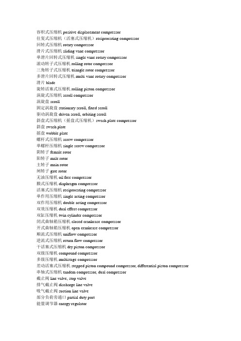
容积式压缩机positive displacement compressor往复式压缩机(活塞式压缩机)reciprocating compressor回转式压缩机rotary compressor滑片式压缩机sliding vane compressor单滑片回转式压缩机single vane rotary compressor滚动转子式压缩机rolling rotor compressor三角转子式压缩机triangle rotor compressor多滑片回转式压缩机multi-vane rotary compressor滑片blade旋转活塞式压缩机rolling piston compressor涡旋式压缩机scroll compressor涡旋盘scroll固定涡旋盘stationary scroll, fixed scroll驱动涡旋盘driven scroll, orbiting scroll斜盘式压缩机(摇盘式压缩机)swash plate compressor斜盘swash plate摇盘wobble plate螺杆式压缩机screw compressor单螺杆压缩机single screw compressor阴转子female rotor阳转子male rotor主转子main rotor闸转子gate rotor无油压缩机oil free compressor膜式压缩机diaphragm compressor活塞式压缩机reciprocating compressor单作用压缩机single acting compressor双作用压缩机double acting compressor双效压缩机dual effect compressor双缸压缩机twin cylinder compressor闭式曲轴箱压缩机closed crankcase compressor开式曲轴箱压缩机open crankcase compressor顺流式压缩机uniflow compressor逆流式压缩机return flow compressor干活塞式压缩机dry piston compressor双级压缩机compound compressor多级压缩机multistage compressor差动活塞式压缩机stepped piston compound compressor, differential piston compressor 串轴式压缩机tandem compressor, dual compressor截止阀line valve, stop valve排气截止阀discharge line valve吸气截止阀suction line valve部分负荷旁通口partial duty port能量调节器energy regulator容量控制滑阀capacity control slide valve容量控制器capacity control消声器muffler联轴节coupling曲轴箱crankcase曲轴箱加热器crankcase heater轴封crankcase seal, shaft seal填料盒stuffing box轴封填料shaft packing机械密封mechanical seal波纹管密封bellows seal转动密封rotary seal迷宫密封labyrinth seal轴承bearing滑动轴承sleeve bearing偏心环eccentric strap滚珠轴承ball bearing滚柱轴承roller bearing滚针轴承needle bearing止推轴承thrust bearing外轴承pedestal bearing臼形轴承footstep bearing轴承箱bearing housing止推盘thrust collar偏心销eccentric pin曲轴平衡块crankshaft counterweight, crankshaft balance weight 曲柄轴crankshaft偏心轴eccentric type crankshaft曲拐轴crank throw type crankshaft连杆connecting rod连杆大头crank pin end连杆小头piston pin end曲轴crankshaft主轴颈main journal曲柄crank arm, crank shaft曲柄销crank pin曲拐crank throw曲拐机构crank-toggle阀盘valve disc阀杆valve stem阀座valve seat阀板valve plate阀盖valve cage阀罩valve cover阀升程限制器valve lift guard阀升程valve lift阀孔valve port吸气口suction inlet压缩机气阀compressor valve吸气阀suction valve排气阀delivery valve圆盘阀disc valve环片阀ring plate valve簧片阀reed valve舌状阀cantilever valve条状阀beam valve提升阀poppet valve菌状阀mushroom valve杯状阀tulip valve缸径cylinder bore余隙容积clearance volume附加余隙(补充余隙)clearance pocket活塞排量swept volume, piston displacement理论排量theoretical displacement实际排量actual displacement实际输气量actual displacement, actual output of gas 气缸工作容积working volume of the cylinder活塞行程容积piston displacement气缸cylinder气缸体cylinder block气缸壁cylinder wall水冷套water cooled jacket气缸盖(气缸头)cylinder head安全盖(假盖)safety head假盖false head活塞环piston ring气环sealing ring刮油环scraper ring油环scrape ring活塞销piston pin活塞piston活塞行程piston stroke吸气行程suction stroke膨胀行程expansion stroke压缩行程compression stroke排气行程discharge stroke升压压缩机booster compressor立式压缩机vertical compressor卧式压缩机horizontal compressor角度式压缩机angular type compressor对称平衡型压缩机symmetrically balanced type compressor CQ螺纹球阀CQ Thread Ball ValvesL形三通式L-pattern three wayT形三通式T-pattern three way安全阀Safety valve暗杆闸阀Inside screw nonrising stem type gate valve百叶窗;闸板shutter百叶窗式挡板louver damper摆阀式活塞泵swing gate piston pump保温式Steam jacket type报警阀alarm valve报警阀;信号阀;脉冲阀sentinel valve背压调节阀back pressure regulating valve背压率Rate of back pressuec本体阀杆密封body stem seal波纹管阀Bellows valves波纹管密封阀bellow sealed valve波纹管密封式Bellows seal type波纹管平衡式安全阀Bellows seal balance safety valve波纹管式减压阀Bellows reducing valve波纹管式减压阀Bellows weal reducing valve薄膜thin film薄膜;隔膜diaphragm薄膜式减压阀Diapjragm reducing valve薄型闸阀Thin Gate Valves不封闭式Unseal type槽车球阀Tank Lorry Ball Valves颤振Flutter常闭式Normally closed type常开式Normally open type超低温阀门Cryogenic valve超高压阀门Super high pressure valve超过压力Overpressure of a safety valve衬胶隔膜阀rubber lined diaphragm衬胶截止阀rubber lined globe valve垂直板式蝶阀Vertical disc type butterfly valve磁耦合截止阀Magnetic Co-operate Globe Valves带补充载荷的安全阀Supplementary loaded safety valve带辅助装置的安全阀Assisted safety valve单阀碟双面平行密封闸阀parallel single disk gate valve单口排气阀Single Opening Exhaust Valves单向阀Non-return Valve单闸板Single gate disc单闸板平板闸阀Single Disc Flat Gate Valves弹簧薄膜式减压阀Spring diaphragm reducing valve弹簧式安全阀Direct spring loaded safety valve弹簧座Spring plate弹性闸板Flexible gate disc当量计算排量Equivalent calculated capacity挡板damper导阀Pilot valve导向套Valve guide disc guide低温阀门Sub-zero valve低压阀门Low pressure valve底阀bottom valve底阀Foot valve电磁动装置Eletro magnetic actuator电磁阀magnetic valve电磁阀solenoid valve电磁-液动装置Eletro magnetichydraulic actuator电动阀mortor operated valve电动阀motorized valve电动截止阀Electric Actuated Stop Valves电动平行式双闸板闸板Electric Double Disk Parallel Gate Valves 电动楔式闸阀Electric Actuated Wedge Gate Valves电动装置Electric actuator电-液动装置Eletro hydraulic actuator电液伺服阀electro-hydraulic servovalve调节弹簧Regulation spring调节阀adjusting valve调节阀control valve调节阀regulating valve调节螺套Adjusting bolt Adjusting screw调节圈Adjusting ring蝶板Disc蝶阀;瓣阀butterfly valve蝶阀;瓣阀;拍门;铰链阀flap valve蝶式缓冲止回阀Butterfly Type Non-slam Check蝶式止回阀Butterfly swing check valve定比减压阀Proprutioning pressure reducing valve定差减压阀Fixed differential reducing valve定值减压阀Fixed pressure reducing valve动态特性Dynamic characteristics对焊连接阀Buttwelding valves对夹蝶板阀Wafer plate valves对夹式衬胶蝶阀Wafer Type Butterfly Valves with Rubber Itning对夹式阀门Clamp valves对夹式止回阀Wafer Check Valves额定排量Certified capacity额定排量系数Derated coefficient of discharge 二通阀Two-way valves阀valve阀板valve deck plate阀板valve plate阀板式活塞泵valve deck plate type piston pump 阀板式活塞泵valve plate type piston pump阀瓣Disc阀操纵杆valve operating rod阀痤槽valve seat recess阀挡valve grid阀挡valve positioner阀挡valve stop阀导杆valve tail rod阀导向器valve guide阀盖bonnet阀盖衬套bonnet bush阀盖垫片bonnet gasket阀杆stem阀杆valve rod阀杆valve spindle阀杆端部尺寸Dimmension of valve stem end阀杆环stem ring阀杆螺母Yoke bushing Yoke nut阀杆填料stem packing阀杆头部尺寸Dimension of valve stem head阀簧valve spring阀簧压板valve spring plate阀控水锤泵valve-controlled hydraulic ram阀框架valve yoke阀门Valve阀门传动装置valve bandle set阀门和管件Valves and Fittings阀门盘根valve packing阀门手柄valve handle阀盘disc阀盘valve disc阀片Disc阀球valve ball阀驱动臂valve driving arm阀驱动臂valve motion arm阀式活塞valve type piston阀式活塞valve type bucket阀室式活塞泵valve box type piston pump阀室式活塞泵(美)valve pot type piston pump阀抬起装置valve lifting device阀体body阀体valve body阀箱valve box阀箱valve cage阀箱valve chest阀箱;阀限位器valve guard阀箱盖cover for valve box阀箱盖valve box cover阀箱式活塞泵(美)turret type piston pump阀形活塞泵valve type piston pump阀座Seat ring阀座valve carrier阀座valve seat(body seat)阀座;阀盘valve seat阀座环seat ring阀座密封嵌条sealing strip for valve seat法兰flange法兰堵头blind flange法兰端flange end法兰接头flange joint法兰连接紧固件(双头螺栓和螺帽)flange bolting 法兰密封面,法兰面flange facing法兰面加工flange facing finish法兰球阀Flange Ball Valves翻板阀Flap反冲盘Disc holder反向作用式减压阀Reverse acting reducing valve反向作用式减压阀Reverse acting reducing valve放空阀emptying valve放气阀air vent valve;vent valve放气阀;排气阀air evacuation valve放泄阀escape valve分置阀室式活塞泵separate valve box type piston pump 分置阀室式活塞泵(美)side pot type piston pump封闭式Seal type浮动式球阀Float ball valve浮球Ball float浮球阀Float Valve阀门种类中英文对照中文英文中文英文阀门valve 通用阀门General valve球阀Ball valve 槽车球阀Tank Lorry Ball ValvesCQ 螺纹球阀CQ Thread Ball Valves 法兰球阀Flange Ball Valves衬里球阀Lining Ball Valves API球阀API Ball valves浮动球阀Float Ball valves 固定球阀Trunnion-mounted Ball valves三通法兰球阀Three Ball valves V 型调节球阀V-Regulating Ball valves闸阀Gate valve 楔式闸阀Wedge Gate Valves法兰闸阀Flange Gate Valves 排渣闸阀Scum Gate V alves薄型闸阀Thin Gate Valves 水封闸阀Water Seal Gate Valves电动楔式闸阀Electric Actuated Wedge Gate Valves 平板闸阀Flat Gate Valve单闸板平板闸阀Single Disc Flat Gate Valves 电动平行式双闸板闸阀Electric Double Disk Parallel Gate Valves双闸板平板闸阀Double Disc Flat Gate Valves 明杆平行式双闸板闸阀Double Disk Parallel Gate Valves截止阀Globe valve 角式截止阀Angle Globe valves门角式截止阀Angle Type Globe V alves 电动截止阀Electric Actuated Stop V alves法兰截止阀Flange Globe Valves 衬里截止阀Lining Globe V alves直流式截止阀Oblique Stop Valves 柱塞截止阀Plunger Globe Valves止回阀Check valve 旋启式止回阀Swing Check Valves对夹式止回阀Wafer Check Valves 蝶式缓冲止回阀Butterfly Type Non-slam Check蝶式缓冲止回阀Butterfly Type Non-slam Check 升降式止回阀Lift Check Valves衬里止回阀Lining Check Valves 微阻缓闭止回阀Tiny Drag Slow Shut Check V alves立式止回阀Vertical Lift Check Valves蝶阀Butterfly Valve 对夹蝶板阀Wafer plate valve衬里蝶阀Lining Butterfly Valves 蜗轮传动蝶阀Butterfly Valves with Gear Actuator对夹式衬胶蝶阀Wafer Type Butterfly Valves with Rubber Itning 金属密封蝶阀Hard Seal Butterfly Valves隔膜阀diaphragm valve 旋塞阀plug valve安全阀safety valve 管道安全阀Piping Safety Valves回转阀rotary valve 减压阀pressure reducing valve减速阀Deceleration valves 泄压阀Decompression valves蒸汽疏水阀Automatic steam trap valve 组合阀Combination valves针形阀Pintle valve 仪表阀Gauge Valves仪表针形截止阀Meter Needle Type Globe Valves 空气阀门Air valves排灰阀Ash valves 吸(抽)气阀Aspirating valves辅助(副)阀Auxiliary valves 平衡阀Balance valves波纹管阀Bellows valves 泄料(放空,排污)阀Blowdown valves制动阀Brake valves 对焊连接阀Buttwelding valves地下管道阀Culvert valves 双口排气球Double Opening Exhaust Valves排水阀Drainage valves 紧急切断阀Emergeny Cut-off Valves排气阀Exhaust valves 浮球式疏水阀Free Float Type Steam Trap手动阀Hand-operated valves 液压继动阀Hydraulic relay valves限位阀Limit valves 衬里三通旋塞阀Lining T-Cock Valves 液位计Liquid Indicator 浆液阀Parallel Slide Valves柱塞阀Plunger valves 压力(増压)阀Pressure valve快速排污阀Quick Draining Valves 电磁阀Solenoid valves 过滤器Strainer 节流阀Throttle Valves阀门术语中英文对照中文英文口径bore公称通径Nominal diameter公称压力Nominal pressure工作温度Operating temperature工作压差Operating pressure工作背压Operating back pressure关闭压力Lockup pressure开启高度Lift壳体试验Shell test壳体试验压力Seal test pressure连接尺寸Conncetion cimension连接形式Type of connection流道面积Flow area流道直径Flow diameter流量孔板flow orifice plate流量特性Flow characteristics流量特性偏差Flow characteristics derivation漏汽量Steam loss密封面Sealing face密封试验Seal test密封试验压力Seal test pressure上密封Back seat上密封试验Back seal test适用介质Suitable medium适用温度Suitable temperature最大过冷度Maximum subcoold temperature最大流量Maximum flow rate最大压差Maximum differential pressure最低工作压力Minimum operating pressure最高背压率Maximum rate of back pressure最高允许压力Maximum allowable pressure最小过冷度Minimum subcooled temperature最小压差Minimum differntial pressure常闭式Normally closed type常开式Normally open type阀门零配件中英文对照中文英文阀体body阀盖bonnet阀盖垫片bonnet gasket阀盖衬套bonnet bush阀瓣Disc阀箱valve box阀座Seat ring阀杆Stem阀杆螺母Yoke bushing Yoke nut 法兰flange填料Packing填料垫Packing seat密封件Sealing挡板damper导向套Valve guide disc guide弹簧座Spring plate轴套Axis Guide球、球芯Ball密封圈Ball seat螺母Mut螺栓Screw弹簧Spring闸板Wedge Disc。
泵中英文对照表
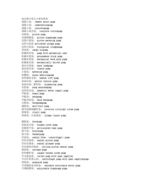
泵名称中英文主要对照表混凝土泵: cement grout pump混凝土泵: cementationpump混凝土泵: concretepump混凝土涡壳泵: concrete volutepump活塞泵: piston pump活塞隔膜泵: piston diaphragm pump活塞计量泵: piston metering pump活性污泥泵 activated sludge pump活性污泥泵: biological sludgepump货油泵: cargo oilpump机械密封泵: pump with mechanical seal机械木浆泵: groundwood stock pump机械木浆泵: mechanical wood pulp pump机械驱动泵: mechanically driven pump基本负荷泵: base loadpump基坑排水泵: trench pump计量泵: metering pump加硼泵: boron additionpump加热器给水泵: heater lift pump加油站泵: petrol station pump加油站泵:配料泵: dispensing pump夹装泵: bung mountedpump家用供水泵: domestic water supply pump甲板泵: board pump甲板泵: deckpump甲板冲洗泵: deck washpump尖舱泵: forepeakpump减摇泵: anti-roll pump渐开线摆线螺杆泵: involute cycloidal screw pump浆液泵: slurry pump浆液泵:污泥液泵: sludge liquor pump脚踏泵: footpump铰接盖式泵: hinged cover pump铰链滑片泵: articulated vane pump接力泵: boostpump接力泵: feederpump径流泵: radial flow (centrifugal)pump径向活塞泵: radial piston pump径向活塞泵: radial plunger pump径向旋转活塞泵: rolling piston radial pump救助泵: salvage pump矩形螺杆泵: square thread screw pump开式旋涡泵: vortex pump with open impeller开式叶轮离心泵: centrifugal pump with open impellerpump 铠装泵: armoured pump可变磁阻电动机泵: variable reluctance motor pump可调隔膜泵: adjustable diaphragm pump可调式混流泵: mixed flow pump with adjustable or variable pitch blades可调式混流泵: semi-axial flow pump with adjustable or variable pitch blades 可调式轴流泵: axial flow pump with adjustable pitch blades可调式轴流泵: propeller pump with adjustable or variable pitch blades可调叶片离心泵: pivotal vane centrifugal pump可逆泵: reversible pump可逆式螺杆泵: reversible screw pump可逆叶片轴流泵: axial flowpump with reversible blades可逆叶片轴流泵: propeller pump with reversible blades ,可携式屏蔽电泵: portable canned motor pump可移式泵: mobile pump可移式泵: portable pump可移式泵: transportable pump可移式消防用泵: portable fire (fighting)pump控制水位用泵: level control库存泵:备用泵: spare pump矿井泵: pit pump矿井泵: shaft pump矿井工作面泵: coal facepump矿井排水泵: mine drainage pump矿井筒袋泵: pit barrel pump矿用泵: mine pump扩散真空泵: diffusion vaccumpump冷冻装置用无轴封泵: glandless pump for refrigerating installation冷剂泵: collantpump冷剂泵: coolantpump冷剂泵: cooling mediumpump冷煤泵: refrigerating medium pump冷凝泵: condensate extractionpump冷凝泵: condensatepump冷凝泵: hot-well pump冷凝泵:热井泵:冷凝水箱泵: hot well pump冷却乳剂泵:肥皂液泵: sudspump冷却水泵: cooling waterpump冷套泵: jacketed pump 〈cooled〉离心泵: centrifugalpump离心机出料泵: centrifugal run-offpump离心喷射泵: centrifugal-jetpump离心-旋涡泵: centrifugal-peripheral pump离心-旋涡泵: centrifugal-turbinepump离子泵: ion〈ization〉pump理想泵: idealized pump立式泵: vertical pump立式框架固定泵: vertical frame mounted pump立式流程泵: vertical process pump立式筒袋泵: vertical barrel pump沥青泵: bitumenpump炼油厂泵: oil refinery pump链传动泵: chain drivepump两级泵: two stage pump裂化装置泵: cracking pump流程泵: process pump流道式叶轮泵: channel impellerpump流体喷射泵: fluid entrainmentpump流体喷射泵: fluid jetpump禄乙烯塑料泵: chlorovinyl plasticpump滤清污水泵: decanted sewagepump滤渣泵: filter residuepump罗茨泵: lobe pump罗茨泵: lobed element pump罗茨泵:凸轮泵: rotary piston libe type pump罗茨泵:凸轮泵〈美〉: lobular pump罗茨真空泵: Root's vacuum pump螺杆泵: screw pump螺纹连接管道泵: pipeline mounted pump with screwed connections螺旋泵: Archimedean screw pump螺旋提水机:阿基米德螺旋泵: inclined Archimedean screw pump螺旋形滑片泵: screw vane pump螺旋形滑片泵: screw vane pump脉冲容积泵: pulsating (chamber) pump脉动计量泵: metering pulse pump煤泥泵: coal slurrypump煤水泵: coalpump迷宫螺旋泵: labyrinth screw pump密闭式螺杆泵: airtight screw pump密闭式螺杆泵: hermetic screw pump密闭式螺杆泵: sealed screw pump模型泵: model pump木浆泵: wood pulp pump木浆泵: wood stock pump内封闭式活塞泵: inside-packed type pistonpump内混合型自吸泵: self-priming pump with inner内密封式活塞泵: internal-packed type piston pump内啮合齿轮泵: crescent gearpump内啮合齿轮泵: crescent seal gearpump内啮合齿轮泵: internal gear pump内配流径向活塞泵: centrally ported radial piston pump内配流径向活塞泵: radial piston pump with interior admission内燃泵:汉弗雷泵: Humphrey pump内燃机驱动泵: engine drivenpump内循环形屏蔽泵: canned motor pump with inner recirculationpump内轴承泵 pump with internal bearing(s)耐碱泵: lye pump耐磨泵: abration resisting pump耐磨泵: wear resisting pump耐蚀泵: corrosion freepump耐蚀泵: corrosion resistingpump挠型转子泵: flexible rotarypump泥浆泵: filter mudpump泥煤泵: turf pump逆洗泵: back washpump凝水回收泵: condensate recoverypump凝水回收泵: condensate returnpump凝水-增压泵: condensate-booster凝水-增压-给水泵: condensate-booster-feedpump牛奶泵: milk pump扭转活塞泵: rocking pintle piston pump农用喷药泵: agricultural spray pump for chemicals排涝泵: land reclamation pump排水泵: draining pump盘状活塞泵: bucket pistonpump配流盘式轴向活塞泵: flatvalve axial pistonpump配流盘式轴向活塞泵: port plate axial piston pump配流盘式轴向活塞泵: valve plate axial piston pump喷灌泵: agricultural spray pump喷淋池泵: spary pond pump喷洒泵:喷淋泵: spary pump喷射泵: injectionpump喷射泵: jet pump喷水泵: injection waterpump喷水推进轴流泵: axial flow pump for water jet propulsion 喷水推进轴流泵: water jet propulsion axial flow pump皮带传动泵: belt drivenpump啤酒泵: beerpump偏心径向活塞泵: radial piston eccentric pump偏心螺杆泵: eccentrie helical totorpump偏心转子泵: eccentric rotarypump平衡转子式滑片泵: balanced rotor vanepump屏蔽泵: canned motorpump起动备用泵: starting up stand-by pump起动用泵: starting up pump起动用抽气泵: evacuationpump起动用罐水泵: priming pump气动隔膜泵: membrane pump with pneumatic drive气动泥浆泵: air-pressure actuated slurry pump气举气体升液泵: gas liftpump气体升液泵: mammoth pump气密电动泵: gastight motor drivenpump气泡泵:曼木特泵:气举泵: air lift pump气泡泵:气举泵: gas bubblepump气体喷射泵: gas jetpump气体喷射真空泵: gas jet vacuumpump气镇泵: gas ballastpump汽车冲洗泵: car wash pump汽车用泵: automobile pump汽轮机驱动泵: turbine driven pump汽轮机直联给水泵: turbine feed pump前置泵,增压泵: boosterpump潜水泵: submerged pump潜水神井泵: borehole submergedpump潜液式螺杆泵: submerged screw pump浅井泵: shallow well pump巧克力输送泵: choclatepump撬式泵:滑移泵: skid mounted pump切线增压泵:部分流泵: partial emission pump切线增压泵:部分流泵: sundyne pump切削冷却乳剂泵: cutting oilpump倾斜活塞泵: inclined piston pump清泥液泵: supernatant liquor pump清水泵: clean waterpump清水泵: clear waterpump清水泵:供水泵: raw water service pump清洗泵: washery pump清洗泵: washing pump清汁泵: evaporator supplypump清汁泵: fitered juice球形活塞泵: ball pistonpump曲柄泵: crankpump曲柄泵: rotative reciprocating pump 曲柄飞轮泵: crank and flywheelpump 取暖用泵: heating pump全负荷泵: full loadpump全可调式混流泵: mixed flow pump with blades adjustable in operation全可调式轴流泵 axial flow pump with blades adjustable in operation全可调式轴流泵: axial flow pump with variable pitch blades全青铜泵: all abronze pump燃油泵: fuelpump燃油泵: fuelpump燃油供给泵: fuel oil supplypump燃油喷射泵: fuel oil injectionpump燃油喷射泵: oil burner pump燃油转送泵: vuel oil transferpump染料泵: dyepump热泵: heat pump热电磁泵: ther‘moelectromagnetic pump热水泵: hot water pump热水循环泵: hot water circulating pump热套泵: jacketed pump 〈heated〉热油泵: hot oil pump人字齿持论泵: herringbone pump人字齿齿轮泵: herringbone gear pump人字齿齿轮泵: double helical gear pump容积泵: pisitive displacement pump容积式真空泵: vacuum displacement pump熔融液泵: melt(liquor)pump熔盐泵: pump for liquid salts鞣革液泵: tannery fleshings pump乳剂泵: emulsionpump软管泵,蠕动泵: flexible tubepump软管泵:蠕动泵: peristaltic pump软管式隔膜泵: flexible tube diaphragmpump软管式隔膜泵: flexible tube membranpump润滑剂泵: lubricating pump三缸曲柄泵: three throw crank pump三缸曲柄泵: triplex pump三缸往复泵: three cylinder reciprocating pump 三缸往复泵: three throw reciprocating pump三流道叶片泵: three channel impeller pump三螺杆泵: three screw pump三叶凸轮泵: three lobe pump三柱塞泵: treble ram pump三柱塞泵: triple plunger pump三作用滑片泵: three cell vane pump扫仓泵:清仓泵: stripping pump沙泵: sand pump沙石泵: gravel pump射流泥浆泵: jet sludge pump深井泵: boreholepump深井泵: deepwellpump深井泵: vertical turbine pump升华泵:提纯泵: sublimation pump生物滤池腐殖质泵: filter-humuspump湿坑泵(美): wet pit pump湿坑泵: wet sump pump湿式电动机泵: wet motor pump湿式真空泵: wet vacuum pump石灰浆泵: lime slurry pump石灰乳泵: milk of lime pump石灰汁泵,清汁泵: clarified juicepump石灰汁泵: limed juice pump石油泵: petroleum pump实验室泵: laboratory pump食品泵: foodpump食品泵: pump for edible fluids试压泵: hydraulic 〈pressure〉test pump手动泵:手压泵: hand pump手动泵:手压泵: lever operated hand pump手动活塞泵: hand piston pump手压泵,手动泵: cottagepump手压抽排泵:手摇泵: hand lift and force手压提升泵: hand lift pump疏水泵: drainage pump输油管线泵:管线泵: oil line pump输油管线泵:管线泵: pipline pump双缸串联蒸汽直动泵: duplex compound steam pump双缸曲柄泵: duplex power pump双缸往复泵: twin cylinder reciprocating pump双缸往复泵: two cylinder reciprocating pump双缸蒸汽直动泵: duplex steam pump双隔膜泵: two diaphragm pump双滑片泵: twin vane pump双壳泵: barrel insertpump双流道叶轮泵: double channel impeller pump双螺杆泵: two screw pump双曲线式罗杆泵: hyperbolic screw pump双凸轮旋转活塞泵: twin lobe pump双涡壳泵: double volute pump双涡壳泵: double-casing volute pump双吸泵: balanced suctionpump双吸泵: double suction pump双吸螺杆泵: double entry screw pump双吸液环泵: double entry liquid ring pump双柱塞泵: double plunger pump双转子滑片泵: double rotor vane pump双转子径向活塞泵: two rotor radial piston pump双作用滑片泵: double action vane pump双作用滑片泵: two cell vane pump双作用活塞泵: double acting piston pump水泵: water pump水环泵: water ring pump水环真空泵: water ring vaccum pump水力采煤泵: monitor pump水泥浆泵: cement slurrypump水喷射泵: water jet pump水套冷却泵: jacket cooling pump水头泵:升水泵:甲板冲洗泵: head pump水压机泵: hydraulic press pump顺磁性氧气泵: paramagnetic oxygen pump伺服系统油泵: governor oil pump伺服系统油泵: telemotor pump饲槽自动泵:家畜自动引水泵: automatic trough pump饲槽自动泵:家畜自动饮水泵: animal self-operated drinking water pump 塑料泵: plastic pump碎渣泵:粉碎机泵: disintegrator pump碎纸浆泵: brokepump梭心转子泵: rotoplunger pump梭心转子泵: shuttle-block pump钛合金泵: titanium alloy pump搪瓷泵: enamel linedpump搪瓷衬里转子泵: enamel lined rotorpump糖膏泵: massecuit pump糖浆泵: syrup(extraction) pump糖蜜泵: molasses pump糖汁泵: sugar liquor pump糖汁泵:〈浆〉汁泵: juice pump陶瓷泵: ceramicpump陶瓷酸泵: ceramic acidpump梯形螺杆泵: trapezoid screw pump甜菜泵: beetpump甜菜根泵: beet tailspump甜菜丝泵: cossettepump通用泵: general servicepump通用泵: ordinary pump通用泵: universal pump筒袋式泵: barrelpump筒袋式油泵: barrel oil pump凸轮泵: cam pump凸轮转子式刮片泵: cam rotor vanepump凸轮转子式刮片泵: cam-vanepump土拉泵:旋流泵: Turo pump托架固定泵: headstock mounted pump托架固定泵: pedestal mounted pump拖拉机泵: tractor pump挖泥泵: dredging pump外混合型自吸泵: self-priming pump with outer recirculation外啮合齿轮泵: external gear pump外啮合齿轮泵: gear-on-gearpump外配流径向活塞泵: peripherally ported radial piston pump外配流径向活塞泵: radial piston pump with exterior admission 外循环形屏蔽泵: canned motor pump with outer recirculationpump 外轴承泵: pump with external bearing(s)往复泵: oscillating displacement pump往复泵: reciprocating pump往复式深井泵: borehole reciprocatingpump微计量泵: micro-metering pump围垦泵: dyke drainagepump尾矿泵: tailings pump卫生泵: sanitary pump温水泵: warm water pump涡壳泵: volute pump卧式泵: horizontal pump污泥泵: sludge pump污水泵: effluentpump污水泵: sewage pump污水泵: waster water污水泛灌泵: sewage broad irrigation pump污水喷灌泵: sewage irrigation spray pump无阀隔膜泵: valveless diaphragm pump无阀活塞泵: valveless pump无阀振动泵: valveless vibration pump无接触密封自吸泵: nontacting sealed selfpriming pump无曲柄泵: cranklesspump无曲柄多缸泵: crank-less multicylinderpump无曲柄污水泵: crankless sewagepump无曲柄消防泵: crankless firepump无叶片泵: bladelesspump无轴封泵: glandlesspump无轴封计量泵: glandless meteringpump五螺杠泵: five screwpump吸附真空泵: adsorption vacuum pump吸入增压泵: suction booster pump吸收泵: absorption pump吸收泵: sorption pump吸水箱水泵: suction box water pump吸水箱水泵: Sven-Pedersen pump洗舱泵: butterworthpump洗矿用泵: ore washing pump洗煤用泵: coal washingpump洗气泵: gas washingpump相对叶轮泵:背靠背叶轮泵: pump with opposed impellers箱筒抽空泵: barrel emptyingpump向心泵: centripetalpump消防泵: fire(fighting)pump消防喷淋系统供水泵: sprinkler system supply pump消化污泥泵,腐泥泵,吸泥泵: digeated sludgepump斜板泵: inclined rotor pump斜板泵: obleque plate pump斜齿齿轮泵: helical gear pump斜缸型轴向柱塞泵: tilting cylinder block type axial plunger 斜盘式(往复)泵: swash plate operated(reciprocating) pump 斜盘式轴向活塞泵: cam plate type axial pistonpump斜盘式轴向活塞泵: wobble plate axial piston pump斜置轴流泵: inclined axial flow pump斜轴式轴向活塞泵: angle-type axial piston pump斜轴式轴向活塞泵: bent axis axial pistonpump谐振隔膜泵: resonance diaphragm pump泄洪泵: flood drainagepump行星转子型蠕动泵: planet rotor pelstaltic pump蓄能泵: storage pump悬臂叶轮泵: pump with overhung impeller悬浮污泥泵: floating sludgepump悬浮液泵: suspension pump悬挂式泵: suspended pump旋浆泵: propeller pump旋流泵:土拉泵: torque flow pump旋涡泵(美): Westco pump旋涡泵: peripheral pump旋涡泵: regenerative pump旋涡泵: vortex pump循环泵: circulatingpump压电泵: piezoelectric pump压力补偿齿轮泵: pressure-balanced gear pump压力水柜泵: hydrophor pump压力油泵: pressure oil pump压缩空气驱动泵: air operated pump压缩空气驱动泵: compressed airpump压载泵: ballastpump盐水泵: brinepump叶轮串并联泵: pump with series or parallel connection impellers 叶片泵: rotodynamic pump叶片泵: turbo pump叶片泵: vane pump叶片可逆转的泵-水轮机: turbine pump with reversible blades液化天然气用低温泵: cryopump for LNG液环泵: liquid ring pump液态金属泵: pump for liquid metals液体泵: liquid pump液体肥料泵: liquid manure pump液体肥料喷射泵: liquid manure spraying pump液体活塞式转子真空泵: rotary vaccum pump with liquid piston液体火箭涡轮泵: liquid rocket turbo pump液体喷射泵: liquid ejector pump液压泵: hydraulic pump液压活塞泵: hydraulic piston pump液氧泵: liquid oxygen pump医用泵: medical pump饮用水泵: drinking water pump应急泵: emergencypump应急泵: jury pump硬铅泵: hard lead pump油泵: oil pump油罐残油泵: tank residue pump油罐车泵: tanker pump油扩散泵: oil diffusion pump油冷却泵: oil cooler pump油轮用泵: oil tanker's pump油喷射泵: oil ejector pump油喷射增压泵: oil ejector booster pump油田泵: oil field pump油蒸汽喷射泵: oil vapour jet pump诱导轮离心泵: centrifugalpump with inducer鱼泵: fishpump原生污泥泵: crude sludgepump原生污泥泵: raw sludge pump原生污水泵: crude sewagepump原生污水泵: raw sewage pump原油泵: crude oilpump原汁泵: raw juice pump原汁循环泵: raw juice circulating pump圆筒感应泵: cylindric inductionpump载热剂泵: heat transfer pump再循环泵: recycle pump增压泵: boostingpump增压给水泵: booster-feed增压扩散泵: booster diffusionpump渣泵: bagassepump粘浆泵: cellulose pulp pump真空泵: vacuum pump蒸汽泵: steam pump蒸汽喷射泵: steam jet pump蒸汽喷射真空泵: steam jet vaccum蒸汽直动活塞泵: direct acting steam pump蒸煮锅放泄泵: digester drain pump蒸煮锅酸液循环泵: digester acid circulatingpump正齿轮泵: spur gear pump直接安装泵: direct mounted pump直联泵: unit construction pump直联泵:单体泵: monoblock pump直列式柱塞泵,管道泵: in-linepump直列式柱塞泵: in-line plungerpump直通活塞泵(美): straight way type piston pump直通活塞泵: straight through type piston pump值勤泵: duty pump值勤泵: service pump纸浆泵: paper stock pump纸浆废水泵: stock drain water pump纸浆水泵:浆水泵: pulp water pump纸浆稀释水泵: stock water pump中比转速泵: medium specific speed pump中开泵: axially splitpump中开泵:水平中开泵: horizontal split pump中速离心泵: moderate-speed centrifugal pump中压泵: middle pressure pump中央密封式活塞泵: centre-packed type pistonpump重介质选矿泵: heavy medium washery pump轴承架固定式泵: pump for with bearing bracket轴流泵: axial flow轴配流径向活塞泵: pintle valve radial piston pump轴配流径向活塞泵: valve spindle radial piston pump轴吸泵: axial inlet pump轴向单吸液循环泵: axial single entry liquid ringpump轴向活塞泵: axial piston pump轴向间隙压力补偿齿轮泵: gearpump with pressure-dependent axial clearance 轴向间隙压力补偿齿轮泵: gearpump with pressurized side plate轴向双吸液环泵: axial double entry liquid ring pump轴向吸入泵: axial suctionpump轴向柱塞泵: axial plungerpump主泵: main pump主冷却剂增压泵: primary coolant booster pump主循环泵: main circulating pump柱塞泵: plunger pump柱塞泵: ram pump柱塞计量泵: plunger metering pump铸钢泵: cast steelpump铸铁泵: all iron pump转子泵: rotor pump转子隔膜泵: rotor diaphragm pump转子滑片泵: roller vane pump转子可抽出式泵 pump with withdrawable rotor assembly 转子可抽出式泵: pull-out type pump装入式泵: built-inpump装入式泵: integral pump装载泵: loading pump自灌泵: self-filling pump自来水泵: water service pump自吸泵: self-priming pump自由活塞泵: free pistonpump纵倾平衡泵: trimming pump钻井冲洗泵: borehole flushingpump水泵英语大全之泵名篇(O-W)obleque plate pump 斜板泵;oil burner pump 燃油喷射泵;oil cooler pump 油冷却泵;oil diffusion pump 油扩散泵;oil ejector booster pump 油喷射增压泵;oil ejector pump 油喷射泵;oil field pump 油田泵;oil line pump 输油管线泵;管线泵;oil pump 油泵;oil refinery pump 炼油厂泵;oil tanker's pump 油轮用泵;oil vapour jet pump 油蒸汽喷射泵;oppesed piston pump 对置活塞泵;ordinary pump 通用泵;ore washing pump 洗矿用泵;oscillating displacement pump 往复泵;paper stock pump 纸浆泵;paramagnetic oxygen pump 顺磁性氧气泵;partial emission pump 切线增压泵;部分流泵;partial load pump (主机)部分负荷泵;peak load pump 高峰负荷泵;pedestal mounted pump 托架固定泵;peripheral pump 旋涡泵;peripherally ported radial piston pump 外配流径向活塞泵;peristaltic pump 软管泵;蠕动泵;petrol station pump 加油站泵;petroleum pump 石油泵;piezoelectric pump 压电泵;pintle valve radial piston pump 轴配流径向活塞泵;pipeline canned motor pump 管道屏蔽泵;pipeline mounted pump 管道泵;pipeline mounted pump with screwed connections 螺纹连接管道泵;pipeline mounted pump with welded connections 焊接管道泵;pipline pump 输油管线泵;管线泵;pisitive displacement pump 容积泵;piston diaphragm pump 活塞隔膜泵;piston metering pump 活塞计量泵;piston pump 活塞泵;piston pump with rotary gate 回转滑阀活塞泵;piston pump with shakeable cylinder 摆动缸活塞泵;pit barrel pump 矿井筒袋泵;pit pump 矿井泵;pitot pump 斗式泵;皮托泵;pivotal vane centrifugal pump 可调叶片离心泵;planet rotor pelstaltic pump 行星转子型蠕动泵;plastic lined pump 衬塑料泵;plastic pump 塑料泵;plunger metering pump 柱塞计量泵;plunger pump 柱塞泵;pneumatic pump 风动泵;port plate axial piston pump 配流盘式轴向活塞泵;portable canned motor pump 可携式屏蔽电泵;portable fire (fighting)pump 可移式消防用泵;portable pump 可移式泵;positive rotary pump 回转容积泵;power pump 动力往复泵;曲柄泵;power station pump 电厂泵;pressure oil pump 压力油泵;pressure-balanced gear pump 压力补偿齿轮泵;primary coolant booster pump 主冷却剂增压泵;priming pump 起动用罐水泵;process pump 流程泵;product pump 产品泵;物料泵;propeller pump 旋浆泵;propeller pump with adjustable or variable pitch blades 可调式轴流泵;propeller pump with reversible blades ,可逆叶片轴流泵;proportioning pump 比例泵;pull-out type pump 转子可抽出式泵;pulp water pump 纸浆水泵;浆水泵;pulsating (chamber) pump 脉冲容积泵;pump for acid washing of boiler 锅炉酸洗泵;pump for edible fluids 食品泵;pump for liquid metals 液态金属泵;pump for liquid salts 熔盐泵;pump for pipe system 管网泵;pump for water -borne solids 固体输送泵;pump for with bearing bracket 轴承架固定式泵;pump with bowl-type vaned casing 导流壳式多级泵;pump with cyclic electromagnetic drive 电磁驱动泵;pump with enclosed impellers 闭式叶轮泵;pump with external bearing(s) 外轴承泵;pump with internal bearing(s) 内轴承泵pump with mechanical seal 机械密封泵;pump with nonrotating cylinder 固定刚体泵;pump with opposed impellers 相对叶轮泵;背靠背叶轮泵;pump with overhung impeller 悬臂叶轮泵;pump with series or parallel connection impellers 叶轮串并联泵;pump with withdrawable rotor assembly 转子可抽出式泵radial flow (centrifugal)pump 径流泵;radial piston eccentric pump 偏心径向活塞泵;radial piston pump 径向活塞泵;radial piston pump with exterior admission 外配流径向活塞泵;radial piston pump with interior admission 内配流径向活塞泵;radial plunger pump 径向活塞泵;radially split pump 分段泵;径向剖分泵;ram pump 柱塞泵;raw juice circulating pump 原汁循环泵;raw juice pump 原汁泵;raw liquor pump 粗糖泵;原液泵;raw sewage pump 原生污水泵;raw sludge pump 原生污泥泵;raw water service pump 清水泵;供水泵;reactor pump 反应堆泵;reciprocating pump 往复泵;reciprocating pump with counterrunning piston 对向活塞泵;reciprocating pump with pistons in V-type arrangement V型活塞泵;reciprocating pump with unidirectional piston 单向活塞泵;recycle pump 再循环泵;reflux pump 回流泵;refrigerating medium pump 冷煤泵;regenerative pump 旋涡泵;resonance diaphragm pump 谐振隔膜泵;return sludge pump 回流污泥泵;reversible pump 可逆泵;reversible screw pump 可逆式螺杆泵;rocker arm pump 变行程往复泵;rocking arm pump 杆式泵;rocking pintle piston pump 扭转活塞泵;roller pump 滚轮泵;roller vane pump 转子滑片泵;rolling piston radial pump 径向旋转活塞泵;rolling vane pump 回转滑片泵;Root's vacuum pump 罗茨真空泵;rotaru piston pump with slide gate !pump 滑阀式回转活塞泵;rotary meterring pump 回转式计量泵;rotary piston libe type pump 罗茨泵;凸轮泵;rotary piston pump 回转式活塞泵;rotary plunger pump 回转式柱塞泵;rotary pump 回转泵;rotary vaccum pump 回转式真空泵;rotary vaccum pump with liquid piston 液体活塞式转子真空泵;rotary vane pump 回转式滑片泵;rotary vane vaccum pump 回转式叶片真空泵;rotary-block radial pump 缸体旋转式径向活塞泵;rotary-displacement pump 回转式容积泵;rotating vane pump 回转式滑片泵;rotative reciprocating pump 曲柄泵;rotodynamic pump 叶片泵;rotoplunger pump 梭心转子泵;rotor diaphragm pump 转子隔膜泵;rotor pump 转子泵;rubber lined pump 衬胶泵;rubber lined vaccum 衬胶真空泵;salvage pump 救助泵;sand pump 沙泵;sanitary pump 卫生泵;scoop pump 斗式泵;screw pump 螺杆泵;screw pump with square thread 方形螺杆泵;screw vane pump 螺旋形滑片泵;sea water pump 海水泵;sealed screw pump 密闭式螺杆泵;sediment pump 沉积物泵;seed(ing)sludge pump 腐泥引进泵;接种污泥泵;segmental type pump 分段式多级泵;self-filling pump 自灌泵;self-priming pump 自吸泵;self-priming pump with inner recirculation 内混合型自吸泵;self-priming pump with outer recirculation 外混合型自吸泵;self-priming pump with recirculation 混合型自吸泵;semi-axial flow pump 混流泵;semi-axial flow pump with adjustable or variable pitch blades 可调式混流泵;semi-rotary(wing) pump 摆动泵;separate valve box type piston pump 分置阀室式活塞泵;service pump 值勤泵;sewage broad irrigation pump 污水泛灌泵;sewage irrigation spray pump 污水喷灌泵;sewage pump 污水泵;shaft pump 矿井泵;shallow well pump 浅井泵;ships pump 船用泵;shuttle-block pump 梭心转子泵;side channel pump 侧流道泵;side pot type piston pump 分置阀式活塞泵;side suction pump 侧吸泵;simplex power pump 单杠曲柄泵;simplex steam pump 单杠蒸汽直动泵;single (power)pump 单杠曲柄泵(美);single (steam)pump 单杠蒸汽直动泵(美);single action piston pump 单作用活塞泵;single action vane pump 单作用滑片泵;single cell vane pump 单作用滑片泵;single channel impeller pump 单流道叶轮泵;single cylinder (reciprocating) pump 单杠往复泵;single entry pump 单吸泵;single lobe pump 单凸轮泵;single plunger pump 单柱塞泵;single power pump 单杠曲柄泵(美);single stage pump 单吸泵;single steam pump 单杠蒸汽直动泵(美);single suction pump 单吸泵;sinking pump 吊泵;skid mounted pump 撬式泵;滑移泵;skirt mounted pump 灯笼架支承泵;sliding vane pump 滑片泵;sliding vane vacuum pump 滑片真空泵;slipper pump 滑履式泵;sludge liquor pump 浆液泵;污泥液泵;sludge pump 污泥泵;slurry pump 浆液泵;smalll load pump (主机)低负荷泵;soft rubber lined pump 衬软胶泵;solid (handling)pump 固体输送泵;sorption pump 吸收泵;spare pump 库存泵;备用泵;spray pond pump 喷淋池泵;spray pump 喷洒泵;喷淋泵;sprinkler system supply pump 消防喷淋系统供水泵;spur gear pump 正齿轮泵;square thread screw pump 矩形螺杆泵;stage casing pump 分段式多级泵;stainless steel pump 不锈钢泵;standard pump 标准泵;stand-by circulating pump 备用循环泵;stand-by pump 备用泵;starting up pump 起动用泵;starting up stand-by pump 起动备用泵;stationary pump 固定式泵;steam jet pump 蒸汽喷射泵;steam jet vaccum pump 蒸汽喷射真空泵;steam pump 蒸汽泵;stock drain water pump 纸浆废水泵;stock water pump 纸浆稀释水泵;storage pump 蓄能泵;storm water pump 暴雨排水泵;straight through type piston pump 直通活塞泵;straight way type piston pump 直通活塞泵(美);straw pulp pump 草浆泵;stripping pump 扫仓泵;清仓泵;sublimation pump 升华泵;提纯泵;submerged pump 潜水泵;submerged screw pump 潜液式螺杆泵;suction booster pump 吸入增压泵;suction box water pump 吸水箱水泵;suds pump 冷却乳剂泵;肥皂液泵;sugar liquor pump 糖汁泵;sump pump 凹坑排水泵;sundyne pump 切线增压泵;部分流泵;super cavitation pump 超汽蚀泵;supernatant liquor pump 清泥液泵;super-pressure pump 超高压泵;supersonic pump 超声速泵;surface wash pump 表洗泵;suspended pump 悬挂式泵;suspension pump 悬浮液泵;Sven-Pedersen pump 吸水箱水泵;swash plate operated(reciprocating) pump 斜盘式(往复)泵;swing gate piston pump 摆阀式活塞泵;swinging vane pump 摆动滑片泵;syrup(extraction) pump 糖浆泵;tailings pump ,,,,,尾矿泵;tank drainage pump ,,,,,罐柜抽泄泵;tank residue pump ,,,,,油罐残油泵;tanker pump ,,,,,油罐车泵;tannery fleshings pump ,,,,,鞣革液泵;telemotor pump ,,,,,伺服系统油泵;ther‘moelectromagnetic pump ,,,,,热电磁泵;thick sludge pump ,,,,,沉积物泵;three cell vane pump ,,,,,三作用滑片泵;three channel impeller pump ,,,,,三流道叶片泵;three cylinder reciprocating pump ,,,,,三缸往复泵;three lobe pump ,,,,,三叶凸轮泵;three screw pump ,,,,,三螺杆泵;three throw crank pump ,,,,,三缸曲柄泵;three throw reciprocating pump ,,,,,三缸往复泵;tilting cylinder block type axial plunger ,,,,,斜缸型轴向柱塞泵;titanium alloy pump ,,,,,钛合金泵;top inlet pump ,,,,,顶端吸入泵;top return pump ,,,,,回流泵;top suction pump ,,,,,顶端吸入泵;torque flow pump ,,,,,旋流泵;土拉泵;tractor pump ,,,,,拖拉机泵;transportable pump ,,,,,可移式泵;trapezoid screw pump ,,,,,梯形螺杆泵;treble ram pump ,,,,,三柱塞泵;trench pump ,,,,,基坑排水泵;trimming pump ,,,,,纵倾平衡泵;triple plunger pump ,,,,,三柱塞泵;triplex pump ,,,,,三缸曲柄泵;trochoid rotor pump ,,,,,次摆线转子泵;trochoid screw pump ,,,,,次摆线螺杆泵;tubewell pump ,,,,,管式深井泵;tubular type axial flow pump ,,,,,管流泵;直管轴流泵;turbine driven pump ,,,,,汽轮机驱动泵;turbine feed pump ,,,,,汽轮机直联给水泵;turbine pump ,,,,,泵-水轮机;turbine pump with reversible blades ,,,,,叶片可逆转的泵-水轮机;turbo pump ,,,,,叶片泵;turf pump ,,,,,泥煤泵;Turo pump ,,,,,土拉泵;旋流泵;turret type piston pump ,,,,,阀箱式活塞泵(美);twin cylinder reciprocating pump ,,,,,双缸往复泵;twin lobe pump ,,,,,双凸轮旋转活塞泵;twin vane pump ,,,,,双滑片泵;two cell vane pump ,,,,,双作用滑片泵;two cylinder reciprocating pump ,,,,,双缸往复泵;two diaphragm pump ,,,,,双隔膜泵;two rotor radial piston pump ,,,,,双转子径向活塞泵;two screw pump ,,,,,双螺杆泵;two stage pump ,,,,,两级泵;ultrahigh vacuum pump ,,,,,超高真空泵;unchokeable pump ,,,,,不堵塞泵;unit construction pump ,,,,,直联泵;universal pump ,,,,,通用泵;vacuum displacement pump ,,,,,容积式真空泵;vacuum pump ,,,,,真空泵;valve box type piston pump ,,,,,阀室式活塞泵;valve deck plate type piston pump ,,,,,阀板式活塞泵;valve plate axial piston pump ,,,,,配流盘式轴向活塞泵;valve plate type piston pump ,,,,,阀板式活塞泵(美);valve spindle radial piston pump ,,,,,轴配流径向活塞泵;valve type piston pump ,,,,,阀形活塞泵;valveless diaphragm pump ,,,,,无阀隔膜泵;valveless pump ,,,,,无阀活塞泵;valveless vibration pump ,,,,,无阀振动泵;vane pump ,,,,,叶片泵;variable area ratio jet pump ,,,,,变量喷射泵;variable capacity pump ,,,,,变量泵;variable capacity screw ,,,,,变量螺杆泵;variable output pump ,,,,,变量泵;variable reluctance motor pump ,,,,,可变磁阻电动机泵;variable speed pump ,,,,,变速泵;variable stroke reciprocating pump ,,,,,变形程往复泵;vertical barrel pump ,,,,,立式筒袋泵;vertical frame mounted pump ,,,,,立式框架固定泵;vertical process pump ,,,,,立式流程泵;vertical pump ,,,,,立式泵;vertical turbine pump ,,,,,深井泵;viscose spinning pump ,,,,,纺丝泵;volute pump ,,,,,涡壳泵;vortex pump ,,,,,旋涡泵;vortex pump with open impeller ,,,,,开式旋涡泵;vortex pump with shrouded impeller pump ,,,,,闭式旋涡泵;v-type piston pump ,,,,, V型活塞泵;vuel oil transferpump ,,,,,燃油转送泵;walking beam pump ,,,,,杆式泵;wall mounted pump ,,,,,壁式泵;warm water pump ,,,,,温水泵;washery pump ,,,,,清洗泵;washing pump ,,,,,清洗泵;waste paper pulp pump ,,,,,废纸浆泵;waster water pump,,,,,污水泵;water conveying pump ,,,,,供水泵;water jet propulsion axial flow pump ,,,,,喷水推进轴流泵;water jet pump ,,,,,水喷射泵;water pump ,,,,,水泵;water ring pump ,,,,,水环泵;water ring vaccum pump ,,,,,水环真空泵;water service pump ,,,,,自来水泵;water supply pump ,,,,,供水泵;wear resisting pump ,,,,,耐磨泵;Westco pump ,,,,,旋涡泵(美);wet motor pump ,,,,,湿式电动机泵;wet pit pump ,,,,,湿坑泵(美);wet sump pump ,,,,,湿坑泵;wet vacuum pump ,,,,,湿式真空泵;wheel and bucket pump ,,,,,斗轮水车;戽斗水车;。
【翻译必备】水泵中英文对照表
复式气泵
double-casing volute pump
双套涡囊泵
double discharge gear pump
双出口齿轮泵
double-direction gearpump
双向齿轮泵
double-pistonpump
双活塞泵
double-stroke deep well pump
扩散泵
diffuser type centrifugal pump
扩散形离心泵
diode sputter-ion pump
二极管溅射离子泵[抽机]
direct-acting pump
直接联动泵
direct acting steam pump
直动蒸汽泵
direct-current electromagnetic pump
复式双动水泵
duplex geared pump
双齿轮泵
duplex steam pump
双缸汽动泵
E开头地水泵英文单词:
eccentric-cylinder rotary oil pump
偏心缸回转油泵
eccentric driven pump
偏心泵
eccentric sliding vane pump
深井双冲程水泵
double-suction pump
双吸泵
downhole engine pump
井底水力活塞泵
drainage pump
排泄泵
draining pump
排水泵
draw-off pump
抽取泵
dredgepump
吸泥泵,排污泵,泥浆泵
driven well pump
常用泵类英文单词

NEW WORDS OF PUMP’S1. 给料泵;,,,,, chargepump2. 给料泵;,,,,, feedpump3. 工程用泵;,,,,, building site pump4. 工程用泵;,,,,, contractor’spump5. 供水泵;,,,,, water conveying pump6. 供水泵;,,,,, water supply pump7. 汞(蒸汽)泵;,,,,, mercury air pump8. 汞扩散泵;,,,,, mercury diffusion pump9. 汞喷射泵;,,,,, mercury ejector pump10. 汞蒸汽喷射泵;,,,,, mercury vapour jet pump11. 汞蒸汽喷射泵;,,,,, mercury(vapour)jet pump12. 固定刚体泵;,,,,, pump with nonrotating cylinder13. 固定式泵;,,,,, stationary pump14. 固体输送泵;,,,,, pump for water -borne solids15. 固体输送泵;,,,,, solid (handling)pump16. 管道泵;,,,,, pipeline mounted pump17. 管道屏蔽泵;,,,,, pipeline canned motor pump18. 管流泵;直管轴流泵;,,,,, tubular type axial flow pump19. 管式深井泵;,,,,, tubewell pump20. 管网泵;,,,,, pump for pipe system21. 惯性脉冲泵;,,,,, inertia impulsepump22. 惯性无曲柄泵;,,,,, inertia crankiesspump23. 灌溉泵;,,,,, irrigation pump24. 罐柜抽泄泵;,,,,, tank drainage pump25. 滚轮泵;,,,,, roller pump26. 锅炉给水泵;,,,,, BFW pump27. 锅炉给水泵;,,,,, boiler feedpump28. 锅炉回水循环泵;,,,,, boiler return circulatingpump29. 锅炉酸洗泵;,,,,, pump for acid washing of boiler30. 过滤泵;,,,,, filterpump31. 海水泵;,,,,, sea water pump32. 焊接管道泵;,,,,, pipeline mounted pump with welded connections33. 航空用泵;,,,,, aviation pump34. 合金泵;,,,,, alloy pump35. 合金钢泵;,,,,, alloy steel pump36. 恒定轴向间隙齿轮泵;,,,,, fixed axial clearance gearpump37. 恒速度;,,,,, constant speedpump38. 横倾平衡泵;,,,,, heeling pump39. 滑阀式回转活塞泵;,,,,, rotaru piston pump with slide gate !pump40. 滑阀型转子泵;,,,,, eccentric rotary pump with sliding sleeve41. 滑履式泵;,,,,, slipper pump42. 滑片泵;,,,,, sliding vane pump43. 滑片真空泵;,,,,, sliding vane vacuum pump44. 滑油泵;,,,,, lubricating oil pump45. 滑脂泵;,,,,, grease pump46. 化工用泵;,,,,, chemicalpump47. 化学纸浆泵;,,,,, chemical pulppump48. 化学纸浆泵;,,,,, chemical stockpump49. 环壳泵;,,,,, annular casing pump50. 环壳泵;,,,,, circular casingpump51. 环氧树脂泵;,,,,, epoxide resinpump52. 灰渣泵;,,,,, ash pump53. 回流泵;,,,,, reflux pump54. 回流泵;,,,,, top return pump55. 回流污泥泵;,,,,, return sludge pump56. 回水泵;,,,,, backwaterpump57. 回转泵;,,,,, rotary pump58. 回转滑阀活塞泵;,,,,, piston pump with rotary gate59. 回转滑片泵;,,,,, rolling vane pump60. 回转容积泵;,,,,, positive rotary pump61. 回转式滑片泵;,,,,, rotary vane pump62. 回转式滑片泵;,,,,, rotating vane pump63. 回转式活塞泵;,,,,, rotary piston pump64. 回转式计量泵;,,,,, rotary meterring pump65. 回转式容积泵;,,,,, rotary-displacement pump66. 回转式叶片真空泵;,,,,, rotary vane vaccum pump67. 回转式真空泵;,,,,, rotary vaccum pump68. 回转式柱塞泵;,,,,, rotary plunger pump69. 混合型自吸泵;,,,,, self-priming pump with recirculation70. 混料泵;,,,,, contactor pump71. 混料泵;,,,,, mixing pump72. 混流泵;,,,,, mixed flow pump73. 混流泵;,,,,, semi-axial flow pump74. 混凝土泵;,,,,, cement grout pump75. 混凝土泵;,,,,, cementationpump76. 混凝土泵;,,,,, concretepump77. 混凝土涡壳泵;,,,,, concrete volutepump78. 活塞泵;,,,,, piston pump79. 活塞隔膜泵;,,,,, piston diaphragm pump80. 活塞计量泵;,,,,, piston metering pump81. 活性污泥泵,,,,, activated sludge pump82. 活性污泥泵;,,,,, biological sludgepump83. 货油泵;,,,,, cargo oilpump84. 机械密封泵;,,,,, pump with mechanical seal85. 机械木浆泵;,,,,, groundwood stock pump86. 机械木浆泵;,,,,, mechanical wood pulp pump87. 机械驱动泵;,,,,, mechanically driven pump88. 基本负荷泵;,,,,, base loadpump89. 基坑排水泵;,,,,, trench pump90. 计量泵;,,,,, metering pump91. 加硼泵;,,,,, boron additionpump92. 加热器给水泵;,,,,, heater lift pump93. 加油站泵;,,,,, petrol station pump94. 加油站泵;配料泵;,,,,, dispensing pump95. 夹装泵;,,,,, bung mountedpump96. 家用供水泵;,,,,, domestic water supply pump97. 甲板泵;,,,,, board pump98. 甲板泵;,,,,, deckpump99. 甲板冲洗泵;,,,,, deck washpump100. 尖舱泵;,,,,, forepeakpump101. 减摇泵;,,,,, anti-roll pump102. 渐开线摆线螺杆泵;,,,,, involute cycloidal screw pump 103. 浆液泵;,,,,, slurry pump104. 浆液泵;污泥液泵;,,,,, sludge liquor pump105. 水泵相关词汇(3)106. o bleque plate pump 斜板泵;107. o il burner pump 燃油喷射泵;108. o il cooler pump 油冷却泵;109. o il diffusion pump 油扩散泵;110. o il ejector booster pump 油喷射增压泵;111. o il ejector pump 油喷射泵;112. o il field pump 油田泵;113. o il line pump 输油管线泵;管线泵;114. o il pump 油泵;115. o il refinery pump 炼油厂泵;116. o il tanker's pump 油轮用泵;117. o il vapour jet pump 油蒸汽喷射泵;118. o ppesed piston pump 对置活塞泵;119. o rdinary pump 通用泵;120. o re washing pump 洗矿用泵;121. o scillating displacement pump 往复泵;122. p aper stock pump 纸浆泵;123. p aramagnetic oxygen pump 顺磁性氧气泵;124. p artial emission pump 切线增压泵;部分流泵;125. p artial load pump (主机)部分负荷泵;126. p eak load pump 高峰负荷泵;127. p edestal mounted pump 托架固定泵;128. p eripheral pump 旋涡泵;129. p eripherally ported radial piston pump 外配流径向活塞泵;130. p eristaltic pump 软管泵;蠕动泵;131. p etrol station pump 加油站泵;132. p etroleum pump 石油泵;133. p iezoelectric pump 压电泵;134. p intle valve radial piston pump 轴配流径向活塞泵;135. p ipeline canned motor pump 管道屏蔽泵;136. p ipeline mounted pump 管道泵;137. p ipeline mounted pump with screwed connections 螺纹连接管道泵;138. p ipeline mounted pump with welded connections 焊接管道泵;139. p ipline pump 输油管线泵;管线泵;140. p isitive displacement pump 容积泵;141. p iston diaphragm pump 活塞隔膜泵;142. p iston metering pump 活塞计量泵;143. p iston pump 活塞泵;144. p iston pump with rotary gate 回转滑阀活塞泵;145. p iston with shakeable cylinder 摆动缸活塞泵;146. p it barrel pump 矿井筒袋泵;147. p it pump 矿井泵;148. p itot pump 斗式泵;皮托泵;149. p ivotal vane centrifugal pump 可调叶片离心泵;150. p lanet rotor pelstaltic pump 行星转子型蠕动泵;151. p lastic lined pump 衬塑料泵;152. p lastic pump 塑料泵;153. p lunger metering pump 柱塞计量泵;154. p lunger pump 柱塞泵;155. p neumatic pump 风动泵;156. p ort plate axial piston pump 配流盘式轴向活塞泵;157. p ortable canned motor pump 可携式屏蔽电泵;158. p ortable fire (fighting)pump 可移式消防用泵;159. p ortable pump 可移式泵;160. p ositive rotary pump 回转容积泵;161. p ower pump 动力往复泵;曲柄泵;162. p ower station pump 电厂泵;163. p ressure oil pump 压力油泵;164. p ressure-balanced gear pump 压力补偿齿轮泵;165. p rimary coolant booster pump 主冷却剂增压泵;166. p riming pump 起动用罐水泵;167. p rocess pump 流程泵;168. p roduct pump 产品泵;物料泵;169. p ropeller pump 旋浆泵;170. p ropeller pump with adjustable or variable pitch blades 可调式轴流泵;171. p ropeller pump with reversible blades , 可逆叶片轴流泵;172. p roportioning pump 比例泵;173. p ull-out type pump 转子可抽出式泵;174. p ulp water pump 纸浆水泵;浆水泵;175. p ulsating (chamber)pump 脉冲容积泵;176. p ump for acid washing of boiler 锅炉酸洗泵;177. p ump for edible fluids 食品泵;178. p ump for liquid ls 液态金属泵;179. p ump for liquid salts 熔盐泵;180. p ump for pipe system 管网泵;181. p ump for water -borne solids 固体输送泵;182. p ump for with bearing bracket 轴承架固定式泵;183. p ump with bowl-type vaned casing 导流壳式多级泵;184. p ump with cyclic electromagnetic drive 电磁驱动泵;185. p ump with enclosed impellers 闭式叶轮泵;186. p ump with external bearing(s) 外轴承泵;187. p ump with internal bearing(s) 内轴承泵188. p ump with mechanical seal 机械密封泵;189. p ump with nonrotating cylinder 固定刚体泵;190. p ump with opposed impellers 相对叶轮泵;背靠背叶轮泵;191. p ump with overhung impeller 悬臂叶轮泵;192. p ump with series or parallel connection impellers 叶轮串并联泵;193. p ump with withdrawable rotor assembly 转子可抽出式泵194. r adial flow (centrifugal)pump 径流泵;195. r adial piston eccentric pump 偏心径向活塞泵;196. r adial piston pump 径向活塞泵;197. r adial piston pump with exterior admission 外配流径向活塞泵;198. r adial piston pump with interior admission 内配流径向活塞泵;199. r adial plunger pump 径向活塞泵;200. r adially split pump 分段泵;径向剖分泵;201. r am pump 柱塞泵;202. r aw juice circulating pump 原汁循环泵;203. r aw juice pump 原汁泵;204. r aw liquor pump 粗糖泵;原液泵;205. r aw sewage pump 原生污水泵;206. r aw sludge pump 原生污泥泵;207. r aw water service pump 清水泵;供水泵;208. r eactor pump 反应堆泵;209. r eciprocating pump 往复泵;210. r eciprocating pump with counterrunning piston 对向活塞泵;211. r eciprocating pump with pistons in V-type arrangement V型活塞泵;212. r eciprocating pump with unidirectional piston 单向活塞泵;213. r ecycle pump 再循环泵;214. r eflux pump 回流泵;215. r efrigerating medium pump 冷煤泵;216. r egenerative pump 旋涡泵;217. r esonance diaphragm pump 谐振隔膜泵;218. r eturn sludge pump 回流污泥泵;219. r eversible pump 可逆泵;220. r eversible screw pump 可逆式螺杆泵;221. r ocker arm pump 变行程往复泵;222. r ocking arm pump 杆式泵;223. r ocking pintle piston pump 扭转活塞泵;224. r oller pump 滚轮泵;225. r oller vane pump 转子滑片泵;226. r olling piston radial pump 径向旋转活塞泵;227. r olling vane pump 回转滑片泵;228. R oot's vacuum pump 罗茨真空泵;229. r otaru piston pump with slide gate !pump 滑阀式回转活塞泵;230. r otary meterring pump 回转式计量泵;231. r otary piston libe type pump 罗茨泵;凸轮泵;232. r otary piston pump 回转式活塞泵;233. r otary plunger pump 回转式柱塞泵;234. r otary pump 回转泵;235. r otary vaccum pump 回转式真空泵;236. r otary vaccum pump with liquid piston 液体活塞式转子真空泵;237. r otary vane pump 回转式滑片泵;238. r otary vane vaccum pump 回转式叶片真空泵;239. r otary-block radial pump 缸体旋转式径向活塞泵;240. r otary-displacement pump 回转式容积泵;241. r otating vane pump 回转式滑片泵;242. r otative reciprocating pump 曲柄泵;243. r otodynamic pump 叶片泵;244. r otoplunger pump 梭心转子泵;245. r otor diaphragm pump 转子隔膜泵;246. r otor pump 转子泵;247. r ubber lined pump 衬胶泵;248. r ubber lined vaccum 衬胶真空泵;249. s alvage pump 救助泵;250. s and pump 沙泵;251. s anitary pump 卫生泵;252. s coop pump 斗式泵;253. s crew pump 螺杆泵;254. s crew pump with square thread 方形螺杆泵;255. s crew vane pump 螺旋形滑片泵;256. s ea water pump 海水泵;257. s ealed screw pump 密闭式螺杆泵;258. s ediment pump 沉积物泵;259. s eed(ing)sludge pump 腐泥引进泵;接种污泥泵;260. s egmental type pump 分段式多级泵;261. s elf-filling pump 自灌泵;262. s elf-priming pump 自吸泵;263. s elf-priming pump with inner recirculation 内混合型自吸泵;264. s elf-priming pump with outer recirculation 外混合型自吸泵;265. s elf-priming pump with recirculation 混合型自吸泵;266. s emi-axial flow pump 混流泵;267. s emi-axial flow pump with adjustable or variable pitch blades 可调式混流泵;268. s emi-rotary(wing)pump 摆动泵;269. s eparate valve box type piston pump 分置阀室式活塞泵;270. s ervice pump 值勤泵;271. s ewage broad irrigation pump 污水泛灌泵;272. s ewage irrigation spray pump 污水喷灌泵;273. s ewage pump 污水泵;274. s haft pump 矿井泵;275. s hallow well pump 浅井泵;276. s hips pump 船用泵;277. s huttle-block pump 梭心转子泵;278. s ide channel pump 侧流道泵;279. s ide pot type piston pump 分置阀式活塞泵;280. s ide suction pump 侧吸泵;281. s implex power pump 单杠曲柄泵;282. s implex steam pump 单杠蒸汽直动泵;283. s ingle (power)pump 单杠曲柄泵(美);284. s ingle (steam)pump 单杠蒸汽直动泵(美);285. s ingle action piston pump 单作用活塞泵;286. s ingle action vane pump 单作用滑片泵;287. s ingle cell vane pump 单作用滑片泵;288. s ingle channel impeller pump 单流道叶轮泵;289. s ingle cylinder (reciprocating)pump 单杠往复泵;290. s ingle entry pump 单吸泵;291. s ingle lobe pump 单凸轮泵;292. s ingle plunger pump 单柱塞泵;293. s ingle power pump 单杠曲柄泵(美);294. s ingle stage pump 单吸泵;295. s ingle steam pump 单杠蒸汽直动泵(美);296. s ingle suction pump 单吸泵;297. s inking pump 吊泵;298. s kid mounted pump 撬式泵;滑移泵;299. s kirt mounted pump 灯笼架支承泵;300. s liding vane pump 滑片泵;301. s liding vane vacuum pump 滑片真空泵;302. s lipper pump 滑履式泵;303. s ludge liquor pump 浆液泵;污泥液泵;304. s ludge pump 污泥泵;305. s lurry pump 浆液泵;306. s malll load pump (主机)低负荷泵;307. s oft rubber lined pump 衬软胶泵;308. s olid (handling)pump 固体输送泵;309. s orption pump 吸收泵;310. s pare pump 库存泵;备用泵;311. s pary pond pump 喷淋池泵;312. s pary pump 喷洒泵;喷淋泵;313. s prinkler system supply pump 消防喷淋系统供水泵;314. s pur gear pump 正齿轮泵;315. s quare thread screw pump 矩形螺杆泵;316. s tage casing pump 分段式多级泵;317. s tainless steel pump 不锈钢泵;318. s tandard pump 标准泵;319. s tand-by circulating pump 备用循环泵;320. s tand-by pump 备用泵;321. s tarting up pump 起动用泵;322. s tarting up stand-by pump 起动备用泵;323. s tationary pump 固定式泵;324. s team jet pump 蒸汽喷射泵;325. s team jet vaccum 蒸汽喷射真空泵;326. s team pump 蒸汽泵;327. s tock drain water pump 纸浆废水泵;328. s tock water pump 纸浆稀释水泵;330. s torm water pump 暴雨排水泵;331. s traight through type piston pump 直通活塞泵;332. s traight way type piston pump 直通活塞泵(美);333. s traw pulp pump 草浆泵;334. s tripping pump 扫仓泵;清仓泵;335. s ublimation pump 升华泵;提纯泵;336. s ubmerged pump 潜水泵;337. s ubmerged screw pump 潜液式螺杆泵;338. s uction booster pump 吸入增压泵;339. s uction box water pump 吸水箱水泵;340. s udspump 冷却乳剂泵;肥皂液泵;341. s ugar liquor pump 糖汁泵;342. s ump pump 凹坑排水泵;343. s undyne pump 切线增压泵;部分流泵;344. s uper cavitation pump 超汽蚀泵;345. s upernatant liquor pump 清泥液泵;346. s uper-pressure pump 超高压泵;347. s upersonic pump 超声速泵;348. s urface wash pump 表洗泵;349. s uspended pump 悬挂式泵;350. s uspension pump 悬浮液泵;351. S ven-Pedersen pump 吸水箱水泵;352. s wash plate operated(reciprocating)pump 斜盘式(往复)泵;353. s wing gate piston pump 摆阀式活塞泵;354. s winging vane pump 摆动滑片泵;355. s yrup(extraction)pump 糖浆泵;356. t ailings pump 尾矿泵;357. t ank drainage pump 罐柜抽泄泵;358. t ank residue pump 油罐残油泵;360. t annery fleshings pump 鞣革液泵;361. t elemotor pump 伺服系统油泵;362. t her‘moelectromagnetic pump 热电磁泵;363. t hick sludge pump 沉积物泵;364. t hree cell vane pump 三作用滑片泵;365. t hree channel impeller pump 三流道叶片泵;366. t hree cylinder reciprocating pump 三缸往复泵;367. t hree lobe pump 三叶凸轮泵;368. t hree screw pump 三螺杆泵;369. t hree throw crank pump 三缸曲柄泵;370. t hree throw reciprocating pump 三缸往复泵;371. t ilting cylinder block type axial plunger 斜缸型轴向柱塞泵;372. t itanium alloy pump 钛合金泵;373. t op inlet pump 顶端吸入泵;374. t op return pump 回流泵;375. t op suction pump 顶端吸入泵;376. t orque flow pump 旋流泵;土拉泵;377. t ractor pump 拖拉机泵;378. t ransportable pump 可移式泵;379. t rapezoid screw pump 梯形螺杆泵;380. t reble ram pump 三柱塞泵;381. t rench pump 基坑排水泵;382. t rimming pump 纵倾平衡泵;383. t riple plunger pump 三柱塞泵;384. t riplex pump 三缸曲柄泵;385. t rochoid rotor pump 次摆线转子泵;386. t rochoid screw pump 次摆线螺杆泵;387. t ubewell pump 管式深井泵;388. t ubular type axial flow pump 管流泵;直管轴流泵;389. t urbine driven pump 汽轮机驱动泵;390. t urbine feed pump 汽轮机直联给水泵;391. t urbine pump 泵-水轮机;392. t urbine pump with reversible blades 叶片可逆转的泵-水轮机;393. t urbo pump 叶片泵;394. t urf pump 泥煤泵;395. T uro pump 土拉泵;旋流泵;396. t urret type piston pump 阀箱式活塞泵(美);397. t win cylinder reciprocating pump 双缸往复泵;398. t win lobe pump 双凸轮旋转活塞泵;399. t win vane pump 双滑片泵;400. t wo cell vane pump 双作用滑片泵;401. t wo cylinder reciprocating pump 双缸往复泵;402. t wo diaphragm pump 双隔膜泵;403. t wo rotor radial piston pump 双转子径向活塞泵;404. t wo screw pump 双螺杆泵;405. t wo stage pump 两级泵;406. u ltrahigh vacuum pump 超高真空泵;407. u nchokeable pump 不堵塞泵;408. u nit construction pump 直联泵;409. u niversal pump 通用泵;410. v acuum displacement pump 容积式真空泵;411. v acuum pump 真空泵;412. v alve box type piston pump 阀室式活塞泵;413. v alve deck plate type piston pump 阀板式活塞泵;414. v alve plate axial piston pump 配流盘式轴向活塞泵;415. v alve plate type piston pump 阀板式活塞泵(美);416. v alve spindle radial piston pump 轴配流径向活塞泵;417. v alve type piston pump 阀形活塞泵;418. v alveless diaphragm pump 无阀隔膜泵;419. v alveless pump 无阀活塞泵;420. v alveless vibration pump 无阀振动泵;421. v ane pump 叶片泵;422. v ariable area ratio jet pump 变量喷射泵;423. v ariable capacity pump 变量泵;424. v ariable capacity screw 变量螺杆泵;425. v ariable output pump 变量泵;426. v ariable reluctance motor pump 可变磁阻电动机泵;427. v ariable speed pump 变速泵;428. v ariable stroke reciprocating pump 变形程往复泵;429. v ertical barrel pump 立式筒袋泵;430. v ertical mounted pump 立式框架固定泵;431. v ertical process pump 立式流程泵;432. v ertical pump 立式泵;433. v ertical turbine pump 深井泵;434. v iscose spinning pump 纺丝泵;435. v olute pump 涡壳泵;436. v ortex pump 旋涡泵;437. v ortex pump with open impeller 开式旋涡泵;438. v ortex pump with shrouded impeller pump 闭式旋涡泵;439. v-type piston pump V型活塞泵;440. v uel oil transferpump 燃油转送泵;441. w alking beam pump 杆式泵;442. w all mounted pump 壁式泵;443. w arm water pump 温水泵;444. w ashery pump 清洗泵;445. w ashing pump 清洗泵;446. w aste paper pulp pump 废纸浆泵;447. w aster water 污水泵;448. w ater conveying pump 供水泵;449. w ater jet propulsion axial flow pump 喷水推进轴流泵;450. w ater jet pump 水喷射泵;451. w ater pump 水泵;452. w ater ring pump 水环泵;453. w ater ring vaccum pump 水环真空泵;454. w ater service pump 自来水泵;455. w ater supply pump 供水泵;456. w ear resisting pump 耐磨泵;457. W estco pump 旋涡泵(美);458. w et motor pump 湿式电动机泵;459. w et pit pump 湿坑泵(美);460. w et sump pump 湿坑泵;461. w et vacuum pump 湿式真空泵;462. w heel and bucket pump 斗轮水车;戽斗水车;463. w indmill (driven)pump 风车驱动泵;464. w obble plate axial piston pump 斜盘式轴向活塞泵;465. w ood pulp pump 木浆泵;466. w ood stock pump 木浆泵;。
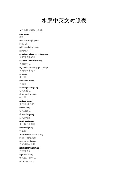
各类水泵英文怎么写

各类水泵名称中英文对照(您可以用ctrl+F键进入查找您要的名称)管道泵;pipeline mounted pump管道屏蔽泵;pipeline canned motor pump离心泵;centrifugal pump螺杆泵;screw pump多级泵;multistage pumpV型活塞泵;reciprocating pump with pistons in V-type arrangementV型活塞泵;v-type piston pump凹坑排水泵;sump pump摆动泵;semi-rotary(wing)pump摆动缸活塞泵;piston with shakeable cylinder摆动滑片泵;swinging vane pump摆阀式活塞泵;swing gate piston pump摆线锣杠泵;cycloidal screwpump半负荷泵〈主机〉;half load pump半贯流式轴流泵;弯管轴流泵;angle-type axial flow pump半开式叶轮离心泵;centrifugal pump with semien closed impellerpump半可调式混流泵;mixed flow pump with blades adjustable when stationary 半可调式轴流泵;axial flow pump with blades adjustable when stationary 暴雨排水泵;storm water pump备用泵;stand-by pump备用循环泵;stand-by circulating pump泵-水轮机;turbine pump泵组;multi cell pump比例泵;dosing pump比例泵;proportioning pump闭式旋涡泵;closed peripheralpump闭式旋涡泵;vortex pump with shrouded impeller pump闭式叶轮泵;pump with enclosed impellers闭式叶轮离心泵;centrifugal pump with shrouded impeller壁式泵;wall mounted pump变量泵;variable capacity pump变量泵;variable output pump变量螺杆泵;variable capacity screw变量喷射泵;variable area ratio jet pump变速泵;variable speed pump变行程往复泵;rocker arm pump变形程往复泵;variable stroke reciprocating pump标准泵;standard pump表洗泵;surface wash pump波纹管泵;bellowspump玻璃泵;glass pump不堵塞泵;chokelesspump不堵塞泵;non-clog(-ging)pump不堵塞泵;unchokeable pump不锈钢泵;stainless steel pump部分负荷泵(主机);partial load pump仓底泵;bilgepump舱壁泵;bulkhead mountedpump草浆泵;straw pulp pump侧流道泵;side channel pump侧吸泵;side suction pump差动活塞泵;differential pistonpump柴油机驱动泵;dieaelpump产品泵;物料泵;product pump长喉管喷射泵;jet pump with long Venturi tube长轴深井泵(美)multistage vertical turbine pump长轴深井泵;borehole shaft driven(centrifugal)pump 超高压泵;super-pressure pump超高真空泵;ultrahigh vacuum pump超汽蚀泵;super cavitation pump超声速泵;supersonic pump沉积物泵;sediment pump沉积物泵;thick sludge pump衬胶泵;rubber lined pump衬胶真空泵;rubber lined vaccum衬青铜泵;bronze fittedpump衬软胶泵;soft rubber lined pump衬塑料泵;plastic lined pump衬硬胶泵;dbonitepump衬硬胶泵;hard rubber lined pump成品泵;discharge pump成品泵;final productpump齿轮泵;gearpump齿轮比例泵;adjustable discharge gear pump齿轮比例泵;gear dosingpump齿轮传动泵;gearedpump冲洗泵;flushingpump除氧化皮泵;descalingpump除氧器供给泵;deaerator liftpump除氧器循环泵;deaerator recirculatingpump传导泵;conductionpump船坞泵;dock pump船用泵;marine pump船用泵;ships pump磁泵,磁感应驱动泵;megnectic pump磁力联轴节齿轮泵;magnectically coupled gear pump 磁蠕动泵;megnectic fluid actuating pump次摆线螺杆泵;trochoid screw pump次摆线转子泵;trochoid rotor pump粗糖泵;原液泵;raw liquor pump带隔片的偏心转子泵;eccentric rotary pump with dividing platepump 带柔性环的偏心滚柱泵;eccentric rotary pump with elastic ringpump 单杠曲柄泵(美);single (power)pump单杠曲柄泵(美);single power pump单杠曲柄泵;simplex power pump单杠往复泵;single cylinder (reciprocating)pump单杠蒸汽直动泵(美);single (steam)pump单杠蒸汽直动泵(美);single steam pump单杠蒸汽直动泵;simplex steam pump单列式柱塞泵;in-line pistonpump单流道叶轮泵;single channel impeller pump单螺杆泵;helical rotor pump单螺杆泵;mono pump单体泵;close coupledpump单体斗式泵;monoblock scoop pump单凸轮泵;single lobe pump单吸泵;single entry pump单吸泵;single stage pump单吸泵;single suction pump单向活塞泵;reciprocating pump with unidirectional piston单叶轮多级泵;multistagepump with single impeller单柱塞泵;single plunger pump单作用滑片泵;single action vane pump单作用滑片泵;single cell vane pump单作用活塞泵;single action piston pump弹性刮片泵;flexible vanepump淡水泵;fresh waterpump导流壳式多级泵;pump with bowl-type vaned casing导页泵;diffuserpump灯笼架固定泵;lantern mounted pump灯笼架支承泵;lantern based pump灯笼架支承泵;skirt mounted pump低比转速泵;low specific speed pump低负荷泵(主机);smalll load pump低速泵;low-speed pump低压泵;low pressure pump低噪音泵;low sound level pump底脚固定泵;foot mountedpump底料泵,塔底液泵;bottomspump底吸泵;bottom inletpump底吸泵;bottom suctionpump地区取热泵;分区供暖泵;district heating pump地下室排水泵;cellar drainagepump地下水排水泵;de-wateringpump地下水排水泵;groundwater drainage pump电厂泵;power station pump电磁泵;electromagneticpump电磁隔膜泵;electromagnetic diaphragmpump电磁计量泵;electromagnetic meteringpump电磁偶合泵;electromagnetically coupledpump电磁喷射泵;electro-magnetic jetpump电磁驱动泵;pump with cyclic electromagnetic drive电磁式比例泵;electromagnetic proportioningpump电动泵;electrically drivenpump电动泵;motor driven pump电动冲脉;electroimpuisepump电动给水泵;electrically driven feedpump电动潜水泵;electro-submersiblepump电动潜水排水泵;electro-submersible drainagepump电离真空泵;ionization vaccum pump吊泵;sinking pump顶端吸入泵;top inlet pump顶端吸入泵;top suction pump定压泵;constant pressurepump动力往复泵;曲柄泵;power pump斗轮水车;戽斗水车;wheel and bucket pump斗式泵;scoop pump斗式泵;皮托泵;pitot pump端部密封式活塞泵;end-packed type pistonpump短喉管喷射泵;jet pump with short Venturi tube短棉绒泵;linters pump对向活塞泵;reciprocating pump with counterrunning piston 对置活塞泵;oppesed piston pump多齿轮泵;multiple gearpump多出口泵;multi dischargepump多缸曲柄泵;multi throw crankpump多缸曲柄泵;multiplexpump多缸曲柄泵;multiplexpump多缸往复泵;multi cylinder(reciprocating)pump多缸往复泵;multi throw(reciprocating)pump多级喷射泵;multistage jet pump多流道叶轮泵;multi channel impellerpump多流式泵;multi flowpump多螺杆泵;multi screwpump多喷嘴喷射泵;multinozzle jetpump多凸轮泵;multi lobepump多用泵;multipurposepump多柱塞泵;multi plungerpump阀板式活塞泵(美);valve plate type piston pump阀板式活塞泵;valve deck plate type piston pump阀室式活塞泵;valve box type piston pump阀箱式活塞泵(美);turret type piston pump阀形活塞泵;valve type piston pump法兰式电动机驱动泵;flanged motor drivenpump法兰悬臂泵;flange mounteapump法兰悬臂泵;flanged overhungpump反应堆泵;reactor pump方形螺杆泵;screw pump with square thread纺丝泵;viscose spinning pump非接触齿轮泵;contactless gearpump非密闭式螺杆泵;non-hermetic screw pump废纸浆泵;waste paper pulp pump分段泵;径向剖分泵;radially split pump分段式多级泵(美)multistage turbine pump分段式多级泵;multistage segmental type pump分段式多级泵;segmental type pump分段式多级泵;stage casing pump分置阀式活塞泵;side pot type piston pump分置阀室式活塞泵;separate valve box type piston pump 分子泵;molecular pump分子空气泵;molecular air pump分子空气泵;molecular drag pump粪便泵;fecalpump粪便泵;分流泵;diverter pump风车驱动泵;windmill (driven)pump风动泵;pneumatic pump风动活塞泵;air-powered piston pump弗里昂泵;freonpump伏辊断头纸浆泵;couch breakpump浮船坞泵;floating dockpump浮动泵;floatingpump辅泵;辅助泵;auxiliary pump辅扫仓泵;辅清仓泵;auxiliary stripping pump腐泥引进泵;接种污泥泵;seed(ing)sludge pump附属泵;attached pump干船坞泵;drg dock pump干坑泵;dry pit pump干坑泵;dry sump pump干式真空泵;dry vacuum pump干式自吸泵;dry self-priming pump杆式泵;rocking arm pump杆式泵;walking beam pump感应泵;inductionpump缸体旋转式径向活塞泵;rotary-block radial pump高比转速泵;higher specific speed pump高峰负荷泵;peak load pump高速泵;high speed pump高速离心泵;high speed centrifugal pump高速叶片泵;high speed rotodynamic pump高速叶片泵;high speed turbo pump高温泵;high temperature pump高压泵;high pressure pump高压加热器疏水泵;high pressure heater drains pump 隔膜泵;diaphragmpump隔膜泵;disc pump隔膜活塞泵;diaphragm pistonpump隔膜式计量泵;diaphragm meteringpump隔膜柱塞泵;diaphragm plungerpump给料泵;chargepump给料泵;feedpump工程用泵;building site pump工程用泵;contractor’spump供水泵;water conveying pump供水泵;water supply pump汞(蒸汽)泵;mercury air pump汞扩散泵;mercury diffusion pump汞喷射泵;mercury ejector pump汞蒸汽喷射泵;mercury vapour jet pump汞蒸汽喷射泵;mercury(vapour)jet pump固定刚体泵;pump with nonrotating cylinder固定式泵;stationary pump固体输送泵;pump for water -borne solids固体输送泵;solid (handling)pump管流泵;直管轴流泵;tubular type axial flow pump 轴流管道泵axial flow piping pump管式深井泵;tubewell pump管网泵;pump for pipe system惯性脉冲泵;inertia impulsepump惯性无曲柄泵;inertia crankiesspump灌溉泵;irrigation pump罐柜抽泄泵;tank drainage pump滚轮泵;roller pump锅炉给水泵;BFW pump锅炉给水泵;boiler feedpump锅炉回水循环泵;boiler return circulatingpump锅炉酸洗泵;pump for acid washing of boiler过滤泵;filterpump海水泵;sea water pump焊接管道泵;pipeline mounted pump with welded connections 航空用泵;aviation pump合金泵;alloy pump合金钢泵;alloy steel pump恒定轴向间隙齿轮泵;fixed axial clearance gearpump恒速度;constant speedpump横倾平衡泵;heeling pump滑阀式回转活塞泵;rotaru piston pump with slide gate !pump 滑阀型转子泵;eccentric rotary pump with sliding sleeve滑履式泵;slipper pump滑片泵;sliding vane pump滑片真空泵;sliding vane vacuum pump滑油泵;lubricating oil pump滑脂泵;grease pump化工用泵;chemicalpump化学纸浆泵;chemical pulppump化学纸浆泵;chemical stockpump环壳泵;annular casing pump环壳泵;circular casingpump环氧树脂泵;epoxide resinpump灰渣泵;ash pump回流泵;reflux pump回流泵;top return pump回流污泥泵;return sludge pump回水泵;backwaterpump回转泵;rotary pump回转滑阀活塞泵;piston pump with rotary gate回转滑片泵;rolling vane pump回转容积泵;positive rotary pump回转式滑片泵;rotary vane pump回转式滑片泵;rotating vane pump回转式活塞泵;rotary piston pump回转式计量泵;rotary meterring pump回转式容积泵;rotary-displacement pump回转式叶片真空泵;rotary vane vaccum pump回转式真空泵;rotary vaccum pump回转式柱塞泵;rotary plunger pump混合型自吸泵;self-priming pump with recirculation混料泵;contactor pump混料泵;mixing pump混流泵;mixed flow pump混流泵;semi-axial flow pump混凝土泵;cement grout pump混凝土泵;cementationpump混凝土泵;concretepump混凝土涡壳泵;concrete volutepump活塞泵;piston pump活塞隔膜泵;piston diaphragm pump活塞计量泵;piston metering pump活性污泥泵activated sludge pump活性污泥泵;biological sludgepump货油泵;cargo oilpump机械密封泵;pump with mechanical seal机械木浆泵;groundwood stock pump机械木浆泵;mechanical wood pulp pump机械驱动泵;mechanically driven pump基本负荷泵;base loadpump基坑排水泵;trench pump计量泵;metering pump加硼泵;boron additionpump加热器给水泵;heater lift pump加油站泵;petrol station pump加油站泵;配料泵;dispensing pump夹装泵;bung mountedpump家用供水泵;domestic water supply pump甲板泵;board pump甲板泵;deckpump甲板冲洗泵;deck washpump尖舱泵;forepeakpump减摇泵;anti-roll pump渐开线摆线螺杆泵;involute cycloidal screw pump 浆液泵;slurry pump浆液泵;污泥液泵sludge liquor pump脚踏泵;footpump铰接盖式泵;hinged cover pump铰链滑片泵;articulated vane pump接力泵;boostpump接力泵;feederpump径流泵;radial flow (centrifugal)pump径向活塞泵;radial piston pump径向活塞泵;radial plunger pump径向旋转活塞泵;rolling piston radial pump救助泵;salvage pump矩形螺杆泵;square thread screw pump开式旋涡泵;vortex pump with open impeller开式叶轮离心泵;centrifugal pump with open impellerpump铠装泵;armoured pump可变磁阻电动机泵;variable reluctance motor pump可调隔膜泵;adjustable diaphragm pump可调式混流泵;mixed flow pump with adjustable or variable pitch blades可调式混流泵;semi-axial flow pump with adjustable or variable pitch blades 可调式轴流泵;axial flow pump with adjustable pitch blades可调式轴流泵;propeller pump with adjustable or variable pitch blades可调叶片离心泵;pivotal vane centrifugal pump可逆泵;reversible pump可逆式螺杆泵;reversible screw pump可逆叶片轴流泵;axial flowpump with reversible blades可逆叶片轴流泵;propeller pump with reversible blades ,可携式屏蔽电泵;portable canned motor pump可移式泵;mobile pump可移式泵;portable pump可移式泵;transportable pump可移式消防用泵;portable fire (fighting)pump控制水位用泵;level control库存泵;备用泵;spare pump矿井泵;pit pump矿井泵;shaft pump矿井工作面泵;coal facepump矿井排水泵;mine drainage pump矿井筒袋泵;pit barrel pump矿用泵;mine pump扩散真空泵;diffusion vaccumpump冷冻装置用无轴封泵;glandless pump for refrigerating installation冷剂泵;collantpump冷剂泵;coolantpump冷剂泵;cooling mediumpump冷煤泵;refrigerating medium pump冷凝泵;condensate extractionpump冷凝泵;condensatepump冷凝泵;hot-well pump冷凝泵;热井泵;冷凝水箱泵;hot well pump冷却乳剂泵;肥皂液泵;sudspump冷却水泵;cooling waterpump冷套泵;jacketed pump 〈cooled〉离心机出料泵;centrifugal run-offpump离心喷射泵;centrifugal-jetpump离心-旋涡泵;centrifugal-peripheral pump离心-旋涡泵;centrifugal-turbinepump离子泵;ion〈ization〉pump理想泵;idealized pump立式泵;vertical pump立式框架固定泵;vertical frame mounted pump立式流程泵;vertical process pump立式筒袋泵;vertical barrel pump沥青泵;bitumenpump炼油厂泵;oil refinery pump链传动泵;chain drivepump链式泵;chainpump两级泵;two stage pump裂化装置泵;cracking pump流程泵;process pump流道式叶轮泵;channel impellerpump流体喷射泵;fluid entrainmentpump流体喷射泵;fluid jetpump禄乙烯塑料泵;chlorovinyl plasticpump滤清污水泵;decanted sewagepump滤渣泵;filter residuepump罗茨泵;lobe pump罗茨泵;lobed element pump罗茨泵;凸轮泵;rotary piston libe type pump罗茨泵;凸轮泵〈美〉;lobular pump罗茨真空泵;Root’s vacuum pump螺纹连接管道泵;pipeline mounted pump with screwed connections 螺旋泵;Archimedean screw pump螺旋提水机;阿基米德螺旋泵;inclined Archimedean screw pump 螺旋形滑片泵;screw vane pump螺旋形滑片泵;screw vane pump脉冲容积泵;pulsating (chamber)pump脉动计量泵;metering pulse pump煤泥泵;coal slurrypump煤水泵;coalpump迷宫螺旋泵;labyrinth screw pump密闭式螺杆泵;airtight screw pump密闭式螺杆泵;hermetic screw pump密闭式螺杆泵;sealed screw pump模型泵;model pump木浆泵;wood pulp pump木浆泵;wood stock pump内封闭式活塞泵;inside-packed type pistonpump内混合型自吸泵;self-priming pump with inner recirculation内密封式活塞泵;internal-packed type piston pump内啮合齿轮泵;crescent gearpump内啮合齿轮泵;crescent seal gearpump内啮合齿轮泵;internal gear pump内配流径向活塞泵;centrally ported radial piston pump内配流径向活塞泵;radial piston pump with interior admissio燃泵;汉弗雷泵;Humphrey pump内燃机驱动泵;engine drivenpump内循环形屏蔽泵;canned motor pump with inner recirculationpump 内轴承泵pump with internal bearing(s)耐碱泵;lye pump耐磨泵;abration resisting pump耐磨泵;wear resisting pump耐蚀泵;corrosion freepump耐蚀泵;corrosion resistingpump耐酸泵;acid pump挠型转子泵;flexible rotarypump泥浆泵;filter mudpump泥煤泵;turf pump逆洗泵;back washpump凝水回收泵;condensate recoverypump凝水回收泵;condensate returnpump凝水-增压泵;condensate-booster凝水-增压-给水泵;condensate-booster-feedpump牛奶泵;milk pump扭转活塞泵;rocking pintle piston pump农用喷药泵;agricultural spray pump for chemicals排涝泵;land reclamation pump排水泵;draining pump盘状活塞泵;bucket pistonpump配流盘式轴向活塞泵;flatvalve axial pistonpump配流盘式轴向活塞泵;port plate axial piston pump配流盘式轴向活塞泵;valve plate axial piston pump喷灌泵;agricultural spray pump喷淋池泵;spary pond pump喷洒泵;喷淋泵;spary pump喷射泵;injectionpump喷射泵;jet pump喷水泵;injection waterpump喷水推进轴流泵;axial flow pump for water jet propulsion喷水推进轴流泵;water jet propulsion axial flow pump皮带传动泵;belt drivenpump啤酒泵;beerpump偏心径向活塞泵;radial piston eccentric pump偏心螺杆泵;eccentrie helical totorpump偏心转子泵;eccentric rotarypump平衡转子式滑片泵;balanced rotor vanepump屏蔽泵;canned motorpump起动备用泵;starting up stand-by pump起动用泵;starting up pump起动用抽气泵;evacuationpump起动用罐水泵;priming pump气动隔膜泵;membrane pump with pneumatic drive 气动泥浆泵;air-pressure actuated slurry pump气举泵,气体升液泵;gas liftpump气举泵;气体升液泵;mammoth pump气密电动泵;gastight motor drivenpump气泡泵;曼木特泵;气举泵;air lift pump气泡泵;气举泵;gas bubblepump气体喷射泵;gas jetpump气体喷射真空泵;gas jet vacuumpump气镇泵;gas ballastpump汽车冲洗泵;car wash pump汽车用泵;automobile pump汽轮机驱动泵;turbine driven pump汽轮机直联给水泵;turbine feed pump前置泵,增压泵;boosterpump潜水泵;submerged pump潜水神井泵;borehole submergedpump潜液式螺杆泵;submerged screw pump浅井泵;shallow well pump巧克力输送泵;choclatepump撬式泵;滑移泵;skid mounted pump切线增压泵;部分流泵;partial emission pump切线增压泵;部分流泵;sundyne pump切削冷却乳剂泵;cutting oilpump倾斜活塞泵;inclined piston pump清泥液泵;supernatant liquor pump清水泵;clean waterpump清水泵;clear waterpump清水泵;供水泵;raw water service pump清洗泵;washery pump清洗泵;washing pump清汁泵;evaporator supplypump清汁泵;fitered juice球形活塞泵;ball pistonpump曲柄泵;crankpump曲柄泵;rotative reciprocating pump曲柄飞轮泵;crank and flywheelpump取暖用泵;heating pump全负荷泵;full loadpump全可调式混流泵;mixed flow pump with blades adjustable in operation 全可调式轴流泵axial flow pump with blades adjustable in operation全可调式轴流泵;axial flow pump with variable pitch blades全青铜泵;all abronze pump燃油泵;fuelpump燃油泵;fuelpump燃油供给泵;fuel oil supplypump燃油喷射泵;fuel oil injectionpump燃油喷射泵;oil burner pump燃油转送泵;vuel oil transferpump染料泵;dyepump热泵;heat pump热电磁泵;ther‘moelectromagnetic pump热水泵;hot water pump热水循环泵;hot water circulating pump热套泵;jacketed pump 〈heated〉热油泵;hot oil pump人字齿持论泵;herringbone pump人字齿齿轮泵;herringbone gear pump人字齿齿轮泵;double helical gear pump容积泵;pisitive displacement pump容积式真空泵;vacuum displacement pump熔融液泵;melt(liquor)pump熔盐泵;pump for liquid salts鞣革液泵;tannery fleshings pump乳剂泵;emulsionpump软管泵,蠕动泵;flexible tubepump软管泵;蠕动泵;peristaltic pump软管式隔膜泵;flexible tube diaphragmpump软管式隔膜泵;flexible tube membranpump润滑剂泵;lubricating pump三缸曲柄泵;three throw crank pump三缸曲柄泵;triplex pump三缸往复泵;three cylinder reciprocating pump三缸往复泵;three throw reciprocating pump三流道叶片泵;three channel impeller pump三螺杆泵;three screw pump三叶凸轮泵;three lobe pump三柱塞泵;treble ram pump三柱塞泵;triple plunger pump三作用滑片泵;three cell vane pump扫仓泵;清仓泵;stripping pump沙泵;sand pump沙石泵;gravel pump射流泥浆泵;jet sludge pump深井泵;boreholepump深井泵;deepwellpump深井泵;vertical turbine pump升华泵;提纯泵;sublimation pump生物滤池腐殖质泵;filter-humuspump湿坑泵(美);wet pit pump湿坑泵;wet sump pump湿式电动机泵;wet motor pump湿式真空泵;wet vacuum pump石灰浆泵;lime slurry pump石灰乳泵;milk of lime pump石灰汁泵,清汁泵;clarified juicepump石灰汁泵;limed juice pump石油泵;petroleum pump验室泵;laboratory pump食品泵;foodpump食品泵;pump for edible fluids试压泵;hydraulic 〈pressure〉test pump手动泵;手压泵;hand pump手动泵;手压泵;lever operated hand pump手动活塞泵;hand piston pump手压泵,手动泵;cottagepump手压抽排泵;手摇泵;hand lift and force手压提升泵;hand lift pump疏水泵;drainage pump输油管线泵;管线泵;oil line pump输油管线泵;管线泵;pipline pump双缸串联蒸汽直动泵;duplex compound steam pump 双缸曲柄泵;duplex power pump双缸往复泵;twin cylinder reciprocating pump双缸往复泵;two cylinder reciprocating pump双缸蒸汽直动泵;duplex steam pump双隔膜泵;two diaphragm pump双滑片泵;twin vane pump双壳泵;barrel insertpump双流道叶轮泵;double channel impeller pump双螺杆泵;two screw pump双曲线式罗杆泵;hyperbolic screw pump双凸轮旋转活塞泵;twin lobe pump双涡壳泵;double volute pump双涡壳泵;double-casing volute pump双吸泵;balanced suctionpump双吸泵;double suction pump双吸螺杆泵;double entry screw pump双吸液环泵;double entry liquid ring pump双柱塞泵;double plunger pump双转子滑片泵;double rotor vane pump双转子径向活塞泵;two rotor radial piston pump双作用滑片泵;double action vane pump双作用滑片泵;two cell vane pump双作用活塞泵;double acting piston pump水泵;water pump水环泵;water ring pump水环真空泵;water ring vaccum pump水力采煤泵;monitor pump水泥浆泵;cement slurrypump水喷射泵;water jet pump水套冷却泵;jacket cooling pump水头泵;升水泵;甲板冲洗泵;head pump水压机泵;hydraulic press pump顺磁性氧气泵;paramagnetic oxygen pump伺服系统油泵;governor oil pump伺服系统油泵;telemotor pump饲槽自动泵;家畜自动引水泵;automatic trough pump饲槽自动泵;家畜自动饮水泵;animal self-operated drinking water pump 塑料泵;plastic pump碎渣泵;粉碎机泵;disintegrator pump碎纸浆泵;brokepump梭心转子泵;rotoplunger pump梭心转子泵;shuttle-block pump钛合金泵;titanium alloy pump搪瓷泵;enamel linedpump搪瓷衬里转子泵;enamel lined rotorpump糖膏泵;massecuit pump糖浆泵;syrup(extraction)pump糖蜜泵;molasses pump糖汁泵;sugar liquor pump糖汁泵;〈浆〉汁泵;juice pump陶瓷泵;ceramicpump陶瓷酸泵;ceramic acidpump梯形螺杆泵;trapezoid screw pump甜菜泵;beetpump甜菜根泵;beet tailspump甜菜丝泵;cossettepump通用泵;general servicepump通用泵;ordinary pump通用泵;universal pump筒袋式泵;barrelpump筒袋式油泵;barrel oil pump凸轮泵;cam pump凸轮转子式刮片泵;cam rotor vanepump凸轮转子式刮片泵;cam-vanepump土拉泵;旋流泵;Turo pump托架固定泵;headstock mounted pump托架固定泵;pedestal mounted pump拖拉机泵;tractor pump挖泥泵;dredging pump外混合型自吸泵;self-priming pump with outer recirculation外啮合齿轮泵;external gear pump外啮合齿轮泵;gear-on-gearpump外配流径向活塞泵;peripherally ported radial piston pump外配流径向活塞泵;radial piston pump with exterior admission外循环形屏蔽泵;canned motor pump with outer recirculationpump 外轴承泵;pump with external bearing(s)往复泵;oscillating displacement pump往复泵;reciprocating pump往复式深井泵;borehole reciprocatingpump微计量泵;micro-metering pump围垦泵;dyke drainagepump尾矿泵;tailings pump卫生泵;sanitary pump温水泵;warm water pump涡壳泵;volute pump卧式泵;horizontal pump污泥泵;sludge pump污水泵;effluentpump污水泵;sewage pump污水泵;waster water污水泛灌泵;sewage broad irrigation pump污水喷灌泵;sewage irrigation spray pump无阀隔膜泵;valveless diaphragm pump无阀活塞泵;valveless pump无阀振动泵;valveless vibration pump无接触密封自吸泵;nontacting sealed selfpriming pump无曲柄泵;cranklesspump无曲柄多缸泵;crank-less multicylinderpump无曲柄污水泵;crankless sewagepump无曲柄消防泵;crankless firepump无叶片泵;bladelesspump无轴封泵;glandlesspump无轴封计量泵;glandless meteringpump五螺杠泵;five screwpump吸附真空泵;adsorption vacuum pump吸入增压泵;suction booster pump吸收泵;absorption pump吸收泵;sorption pump吸水箱水泵;suction box water pump吸水箱水泵;Sven-Pedersen pump洗舱泵;butterworthpump洗矿用泵;ore washing pump洗煤用泵;coal washingpump洗气泵;gas washingpump相对叶轮泵;背靠背叶轮泵;pump with opposed impellers箱筒抽空泵;barrel emptyingpump向心泵;centripetalpump消防泵;fire(fighting)pump消防喷淋系统供水泵;sprinkler system supply pump消化污泥泵,腐泥泵,吸泥泵;digeated sludgepump斜板泵;inclined rotor pump斜板泵;obleque plate pump斜齿齿轮泵;helical gear pump斜缸型轴向柱塞泵;tilting cylinder block type axial plunger斜盘式(往复)泵;swash plate operated(reciprocating)pump斜盘式轴向活塞泵;cam plate type axial pistonpump斜盘式轴向活塞泵;wobble plate axial piston pump斜置轴流泵;inclined axial flow pump斜轴式轴向活塞泵;angle-type axial piston pump斜轴式轴向活塞泵;bent axis axial pistonpump谐振隔膜泵;resonance diaphragm pump泄洪泵;flood drainagepump行星转子型蠕动泵;planet rotor pelstaltic pump蓄能泵;storage pump悬臂叶轮泵;pump with overhung impeller悬浮污泥泵;floating sludgepump悬浮液泵;suspension pump悬挂式泵;suspended pump旋浆泵;propeller pump旋流泵;土拉泵;torque flow pump关键字:泵水泵离心泵描述:长沙三昌泵业有限公司是一家专业从事不锈钢多级泵的泵类生产和销售企业,专营离心泵、多级泵、大型泵、热水泵、冷凝泵、排污泵、大型电站循环泵、次高压多级泵、高压多级泵、油泵、渣泵、泥浆泵、渣浆泵、砂泵、单级双吸中开泵、单级悬臂式离心泵等系列产品。
压缩机专业词汇中英文对照大全,你不收藏算我输!

压缩机专业词汇中英文对照大全,你不收藏算我输!中英对照压缩机分类及配件词汇容积式压缩机 positive displacement compressor往复式压缩机(活塞式压缩机) reciprocating compressor 回转式压缩机 rotary compressor滑片式压缩机 sliding vane compressor单滑片回转式压缩机 single vane rotary compressor滚动转子式压缩机 rolling rotor compressor三角转子式压缩机 triangle rotor compressor多滑片回转式压缩机 multi-vane rotary compressor滑片 blade旋转活塞式压缩机 rolling piston compressor涡旋式压缩机 scroll compressor涡旋盘 scroll固定涡旋盘 stationary scroll, fixed scroll驱动涡旋盘 driven scroll, orbiting scroll斜盘式压缩机(摇盘式压缩机) swash plate compressor 斜盘 swash plate摇盘 wobble plate螺杆式压缩机 screw compressor单螺杆压缩机 single screw compressor阴转子 female rotor阳转子 male rotor主转子 main rotor闸转子 gate rotor无油压缩机 oil free compressor膜式压缩机 diaphragm compressor活塞式压缩机 reciprocating compressor单作用压缩机 single acting compressor双作用压缩机 double acting compressor双效压缩机 dual effect compressor双缸压缩机 twin cylinder compressor闭式曲轴箱压缩机 closed crankcase compressor开式曲轴箱压缩机 open crankcase compressor顺流式压缩机 uniflow compressor逆流式压缩机 return flow compressor干活塞式压缩机 dry piston compressor双级压缩机 compound compressor多级压缩机 multistage compressor差动活塞式压缩机stepped piston compound compressor, differential piston compressor串轴式压缩机 tandem compressor, dual compressor截止阀 line valve, stop valve排气截止阀 discharge line valve吸气截止阀 suction line valve部分负荷旁通口 partial duty port能量调节器 energy regulator容量控制滑阀 capacity control slide valve容量控制器 capacity control消声器 muffler联轴节 coupling曲轴箱 crankcase曲轴箱加热器 crankcase heater轴封 crankcase seal, shaft seal填料盒 stuffing box轴封填料 shaft packing机械密封 mechanical seal波纹管密封 bellows seal转动密封 rotary seal迷宫密封 labyrinth seal轴承 bearing滑动轴承 sleeve bearing偏心环 eccentric strap滚珠轴承 ball bearing滚柱轴承 roller bearing滚针轴承 needle bearing止推轴承 thrust bearing外轴承 pedestal bearing臼形轴承 footstep bearing轴承箱 bearing housing止推盘 thrust collar偏心销 eccentric pin曲轴平衡块crankshaft counterweight, crankshaft balance weight曲柄轴 crankshaft偏心轴 eccentric type crankshaft曲拐轴 crank throw type crankshaft连杆 connecting rod连杆大头 crank pin end连杆小头 piston pin end曲轴 crankshaft主轴颈 main journal曲柄 crank arm, crank shaft曲柄销 crank pin曲拐 crank throw曲拐机构 crank-toggle阀盘 valve disc阀杆 valve stem阀座 valve seat阀板 valve plate阀盖 valve cage阀罩 valve cover阀升程限制器valve lift guard阀升程 valve lift阀孔 valve port吸气口 suction inlet压缩机气阀 compressor valve吸气阀 suction valve排气阀 delivery valve圆盘阀 disc valve环片阀 ring plate valve簧片阀 reed valve舌状阀 cantilever valve条状阀 beam valve提升阀 poppet valve菌状阀 mushroom valve杯状阀 tulip valve缸径 cylinder bore余隙容积 clearance volume附加余隙(补充余隙) clearance pocket活塞排量 swept volume, piston displacement理论排量 theoretical displacement实际排量 actual displacement实际输气量 actual displacement, actual output of gas气缸工作容积 working volume of the cylinder活塞行程容积 piston displacement气缸 cylinder气缸体 cylinder block气缸壁 cylinder wall水冷套 water cooled jacket气缸盖(气缸头) cylinder head安全盖(假盖) safety head假盖 false head活塞环 piston ring气环 sealing ring刮油环 scraper ring油环 scrape ring活塞销 piston pin活塞 piston活塞行程 piston stroke吸气行程 suction stroke膨胀行程 expansion stroke压缩行程 compression stroke排气行程 discharge stroke升压压缩机 booster compressor立式压缩机 vertical compressor卧式压缩机 horizontal compressor角度式压缩机 angular type compressor对称平衡型压缩机 symmetrically balanced type compressor 压缩机参数词汇1. performance parameter 性能参数——表征压缩机主要性能的诸参数,如:气量、压力、温度、功率及噪声、振动等2. constructional parameter 结构参数——表征压缩机结构特点的诸参数,如:活塞力、行程、转速、列数、各级缸径、外形尺寸等3. inlet pressure/suction pressure 吸气压力(吸入压力)——在标准吸气位置气体的平均绝对全压力。
工业用泵术语中英文对照

螺旋形滑片泵;screw vane pump脉冲容积泵;pulsating (chamber)pump脉动计量泵;metering pulse pump煤泥泵;coal slurrypump煤水泵;coalpump迷宫螺旋泵;labyrinth screw pump密闭式螺杆泵;airtight screw pump密闭式螺杆泵;hermetic screw pump密闭式螺杆泵;sealed screw pump模型泵;model pump木浆泵;wood pulp pump木浆泵;wood stock pump内封闭式活塞泵;inside-packed type pistonpump内混合型自吸泵;self-priming pump with inner recirculation内密封式活塞泵;internal-packed type piston pump内啮合齿轮泵;crescent gearpump内啮合齿轮泵;crescent seal gearpump内啮合齿轮泵;internal gear pump内配流径向活塞泵;centrally ported radial piston pump内配流径向活塞泵;radial piston pump with interior admission内燃泵;汉弗雷泵;Humphrey pump内燃机驱动泵;engine driven pump内循环形屏蔽泵;canned motor pump with inner recirculation pump 内轴承泵pump with internal bearing(s)耐碱泵;lye pump耐磨泵;abration resisting pump耐磨泵;wear resisting pump耐蚀泵;corrosion freepump耐蚀泵;corrosion resistingpump耐酸泵;acid pump挠型转子泵;flexible rotarypump泥浆泵;filter mudpump泥煤泵;turf pump逆洗泵;back washpump凝水回收泵;condensate recoverypump凝水回收泵;condensate returnpump凝水-增压泵;condensate-booster凝水-增压-给水泵;condensate-booster-feedpump牛奶泵;milk pump扭转活塞泵;rocking pintle piston pump农用喷药泵;agricultural spray pump for chemicals排涝泵;land reclamation pump排水泵;draining pump盘状活塞泵;bucket pistonpump配流盘式轴向活塞泵;flatvalve axial pistonpump配流盘式轴向活塞泵;port plate axial piston pump喷淋池泵;spary pond pump喷洒泵;喷淋泵;spary pump喷射泵;injection pump喷射泵;jet pump喷水泵;injection water pump喷水推进轴流泵;axial flow pump for water jet propulsion喷水推进轴流泵;water jet propulsion axial flow pump皮带传动泵;belt driven pump啤酒泵;beer pump偏心径向活塞泵;radial piston eccentric pump偏心螺杆泵;eccentrie helical totor pump偏心转子泵;eccentric rotarypump平衡转子式滑片泵;balanced rotor vane pump屏蔽泵;canned motor pumpV型活塞泵;reciprocating pump with pistons in V-type arrangementV型活塞泵;v-type piston pump凹坑排水泵;sump pump摆动泵;semi-rotary(wing)pump摆动缸活塞泵;piston with shakeable cylinder摆动滑片泵;swinging vane pump摆阀式活塞泵;swing gate piston pump摆线锣杠泵;cycloidal screw pump半负荷泵〈主机〉;half load pump半贯流式轴流泵;弯管轴流泵;angle-type axial flow pump半开式叶轮离心泵;centrifugal pump with semien closed impellerpump半可调式混流泵;mixed flow pump with blades adjustable when stationary 半可调式轴流泵;axial flow pump with blades adjustable when stationary暴雨排水泵;storm water pump备用泵;stand-by pump备用循环泵;stand-by circulating pump泵-水轮机;turbine pump泵组;multi cell pump比例泵;dosing pump比例泵;proportioning pump闭式旋涡泵;closed peripheralpump闭式旋涡泵;vortex pump with shrouded impeller pump闭式叶轮泵;pump with enclosed impellers闭式叶轮离心泵;centrifugal pump with shrouded impeller壁式泵;wall mounted pump变量泵;variable capacity pump变量泵;variable output pump变量螺杆泵;variable capacity screw变量喷射泵;variable area ratio jet pump变速泵;variable speed pump标准泵;standard pump表洗泵;surface wash pump波纹管泵;bellowspump玻璃泵;glass pump不堵塞泵;chokelesspump不堵塞泵;non-clog(-ging)pump不堵塞泵;unchokeable pump不锈钢泵;stainless steel pump部分负荷泵(主机);partial load pump仓底泵;bilgepump舱壁泵;bulkhead mountedpump草浆泵;straw pulp pump侧流道泵;side channel pump侧吸泵;side suction pump差动活塞泵;differential pistonpump柴油机驱动泵;dieaelpump产品泵;物料泵;product pump长喉管喷射泵;jet pump with long Venturi tube长轴深井泵(美)multistage vertical turbine pump长轴深井泵;borehole shaft driven(centrifugal)pump 超高压泵;super-pressure pump超高真空泵;ultrahigh vacuum pump超汽蚀泵;super cavitation pump超声速泵;supersonic pump沉积物泵;sediment pump沉积物泵;thick sludge pump衬胶泵;rubber lined pump衬胶真空泵;rubber lined vaccum衬青铜泵;bronze fittedpump衬软胶泵;soft rubber lined pump衬塑料泵;plastic lined pump衬硬胶泵;dbonitepump衬硬胶泵;hard rubber lined pump成品泵;discharge pump成品泵;final productpump齿轮泵;gearpump齿轮比例泵;adjustable discharge gear pump齿轮比例泵;gear dosingpump齿轮传动泵;gearedpump冲洗泵;flushingpump除氧化皮泵;descalingpump除氧器供给泵;deaerator liftpump除氧器循环泵;deaerator recirculatingpump传导泵;conductionpump船坞泵;dock pump磁泵,磁感应驱动泵;megnectic pump磁力联轴节齿轮泵;magnectically coupled gear pump磁蠕动泵;megnectic fluid actuating pump次摆线螺杆泵;trochoid screw pump次摆线转子泵;trochoid rotor pump粗糖泵;原液泵;raw liquor pump带隔片的偏心转子泵;eccentric rotary pump with dividing platepump 带柔性环的偏心滚柱泵;eccentric rotary pump with elastic ringpump 单杠曲柄泵(美);single (power)pump单杠曲柄泵(美);single power pump单杠曲柄泵;simplex power pump单杠往复泵;single cylinder (reciprocating)pump单杠蒸汽直动泵(美);single (steam)pump单杠蒸汽直动泵(美);single steam pump单杠蒸汽直动泵;simplex steam pump单列式柱塞泵;in-line pistonpump单流道叶轮泵;single channel impeller pump单螺杆泵;helical rotor pump单螺杆泵;mono pump单体泵;close coupledpump单体斗式泵;monoblock scoop pump单凸轮泵;single lobe pump单吸泵;single entry pump单吸泵;single stage pump单吸泵;single suction pump单向活塞泵;reciprocating pump with unidirectional piston单叶轮多级泵;multistagepump with single impeller单柱塞泵;single plunger pump单作用滑片泵;single action vane pump单作用滑片泵;single cell vane pump单作用活塞泵;single action piston pump弹性刮片泵;flexible vanepump淡水泵;fresh waterpump导流壳式多级泵;pump with bowl-type vaned casing导页泵;diffuserpump灯笼架固定泵;lantern mounted pump灯笼架支承泵;lantern based pump灯笼架支承泵;skirt mounted pump低比转速泵;low specific speed pump低负荷泵(主机);smalll load pump低速泵;low-speed pump低压泵;low pressure pump低噪音泵;low sound level pump底脚固定泵;foot mountedpump底料泵,塔底液泵;bottomspump地区取热泵;分区供暖泵;district heating pump地下室排水泵;cellar drainagepump地下水排水泵;de-wateringpump地下水排水泵;groundwater drainage pump电厂泵;power station pump电磁泵;electromagneticpump电磁隔膜泵;electromagnetic diaphragmpump电磁计量泵;electromagnetic meteringpump电磁偶合泵;electromagnetically coupledpump电磁喷射泵;electro-magnetic jetpump电磁驱动泵;pump with cyclic electromagnetic drive电磁式比例泵;electromagnetic proportioningpump电动泵;electrically drivenpump电动泵;motor driven pump电动冲脉;electroimpuisepump电动给水泵;electrically driven feedpump电动潜水泵;electro-submersiblepump电动潜水排水泵;electro-submersible drainagepump电离真空泵;ionization vaccum pump吊泵;sinking pump顶端吸入泵;top inlet pump顶端吸入泵;top suction pump定压泵;constant pressurepump动力往复泵;曲柄泵;power pump斗轮水车;戽斗水车;wheel and bucket pump斗式泵;scoop pump斗式泵;皮托泵;pitot pump端部密封式活塞泵;end-packed type pistonpump短喉管喷射泵;jet pump with short Venturi tube短棉绒泵;linters pump对向活塞泵;reciprocating pump with counterrunning piston 对置活塞泵;oppesed piston pump多齿轮泵;multiple gearpump多出口泵;multi dischargepump多缸曲柄泵;multi throw crankpump多缸曲柄泵;multiplexpump多缸曲柄泵;multiplexpump多缸往复泵;multi cylinder(reciprocating)pump多缸往复泵;multi throw(reciprocating)pump多级泵;multistagepump多级喷射泵;multistage jet pump多流道叶轮泵;multi channel impellerpump多流式泵;multi flowpump多螺杆泵;multi screwpump多喷嘴喷射泵;multinozzle jetpump多柱塞泵;multi plungerpump阀板式活塞泵(美);valve plate type piston pump阀板式活塞泵;valve deck plate type piston pump阀室式活塞泵;valve box type piston pump阀箱式活塞泵(美);turret type piston pump阀形活塞泵;valve type piston pump法兰式电动机驱动泵;flanged motor drivenpump法兰悬臂泵;flange mounteapump法兰悬臂泵;flanged overhungpump反应堆泵;reactor pump方形螺杆泵;screw pump with square thread纺丝泵;viscose spinning pump非接触齿轮泵;contactless gearpump非密闭式螺杆泵;non-hermetic screw pump废纸浆泵;waste paper pulp pump分段泵;径向剖分泵;radially split pump分段式多级泵(美)multistage turbine pump分段式多级泵;multistage segmental type pump分段式多级泵;segmental type pump分段式多级泵;stage casing pump分置阀式活塞泵;side pot type piston pump分置阀室式活塞泵;separate valve box type piston pump 分子泵;molecular pump分子空气泵;molecular air pump分子空气泵;molecular drag pump粪便泵;fecalpump粪便泵;分流泵;diverter pump风车驱动泵;windmill (driven)pump风动泵;pneumatic pump风动活塞泵;air-powered piston pump弗里昂泵;freonpump伏辊断头纸浆泵;couch breakpump浮船坞泵;floating dockpump浮动泵;floatingpump辅泵;辅助泵;auxiliary pump辅扫仓泵;辅清仓泵;auxiliary stripping pump腐泥引进泵;接种污泥泵;seed(ing)sludge pump附属泵;attached pump干船坞泵;drg dock pump干坑泵;dry pit pump干坑泵;dry sump pump干式真空泵;dry vacuum pump干式自吸泵;dry self-priming pump杆式泵;rocking arm pump杆式泵;walking beam pump感应泵;inductionpump高比转速泵;higher specific speed pump高峰负荷泵;peak load pump高速泵;high speed pump高速离心泵;high speed centrifugal pump高速叶片泵;high speed rotodynamic pump高速叶片泵;high speed turbo pump高温泵;high temperature pump高压泵;high pressure pump高压加热器疏水泵;high pressure heater drains pump隔膜泵;diaphragmpump隔膜泵;disc pump隔膜活塞泵;diaphragm pistonpump隔膜式计量泵;diaphragm meteringpump隔膜柱塞泵;diaphragm plungerpump给料泵;chargepump给料泵;feedpump工程用泵;building site pump工程用泵;contractor’spump供水泵;water conveying pump供水泵;water supply pump汞(蒸汽)泵;mercury air pump汞扩散泵;mercury diffusion pump汞喷射泵;mercury ejector pump汞蒸汽喷射泵;mercury vapour jet pump汞蒸汽喷射泵;mercury(vapour)jet pump固定刚体泵;pump with nonrotating cylinder固定式泵;stationary pump固体输送泵;pump for water -borne solids固体输送泵;solid (handling)pump管道泵;pipeline mounted pump管道屏蔽泵;pipeline canned motor pump管流泵;直管轴流泵;tubular type axial flow pump管式深井泵;tubewell pump管网泵;pump for pipe system惯性脉冲泵;inertia impulsepump惯性无曲柄泵;inertia crankiesspump灌溉泵;irrigation pump罐柜抽泄泵;tank drainage pump滚轮泵;roller pump锅炉给水泵;BFW pump锅炉给水泵;boiler feedpump锅炉回水循环泵;boiler return circulatingpump锅炉酸洗泵;pump for acid washing of boiler过滤泵;filterpump海水泵;sea water pump焊接管道泵;pipeline mounted pump with welded connections合金钢泵;alloy steel pump恒定轴向间隙齿轮泵;fixed axial clearance gearpump恒速度;constant speedpump横倾平衡泵;heeling pump滑阀式回转活塞泵;rotaru piston pump with slide gate !pump 滑阀型转子泵;eccentric rotary pump with sliding sleeve滑履式泵;slipper pump滑片泵;sliding vane pump滑片真空泵;sliding vane vacuum pump滑油泵;lubricating oil pump滑脂泵;grease pump化工用泵;chemicalpump化学纸浆泵;chemical pulppump化学纸浆泵;chemical stockpump环壳泵;annular casing pump环壳泵;circular casingpump环氧树脂泵;epoxide resinpump灰渣泵;ash pump回流泵;reflux pump回流泵;top return pump回流污泥泵;return sludge pump回水泵;backwaterpump回转泵;rotary pump回转滑阀活塞泵;piston pump with rotary gate回转滑片泵;rolling vane pump回转容积泵;positive rotary pump回转式滑片泵;rotary vane pump回转式滑片泵;rotating vane pump回转式活塞泵;rotary piston pump回转式计量泵;rotary meterring pump回转式容积泵;rotary-displacement pump回转式叶片真空泵;rotary vane vaccum pump回转式真空泵;rotary vaccum pump回转式柱塞泵;rotary plunger pump混合型自吸泵;self-priming pump with recirculation混料泵;contactor pump混料泵;mixing pump混流泵;mixed flow pump混流泵;semi-axial flow pump混凝土泵;cement grout pump混凝土泵;cementationpump混凝土泵;concretepump混凝土涡壳泵;concrete volutepump活塞泵;piston pump活塞隔膜泵;piston diaphragm pump活性污泥泵;biological sludgepump货油泵;cargo oilpump机械密封泵;pump with mechanical seal机械木浆泵;groundwood stock pump机械木浆泵;mechanical wood pulp pump机械驱动泵;mechanically driven pump基本负荷泵;base loadpump基坑排水泵;trench pump计量泵;metering pump加硼泵;boron additionpump加热器给水泵;heater lift pump加油站泵;petrol station pump加油站泵;配料泵;dispensing pump夹装泵;bung mountedpump家用供水泵;domestic water supply pump甲板泵;board pump甲板泵;deckpump甲板冲洗泵;deck washpump尖舱泵;forepeakpump减摇泵;anti-roll pump渐开线摆线螺杆泵;involute cycloidal screw pump浆液泵;slurry pump浆液泵;污泥液泵;sludge liquor pump脚踏泵;footpump铰接盖式泵;hinged cover pump铰链滑片泵;articulated vane pump接力泵;boostpump接力泵;feederpump径流泵;radial flow (centrifugal)pump径向活塞泵;radial piston pump径向活塞泵;radial plunger pump径向旋转活塞泵;rolling piston radial pump救助泵;salvage pump矩形螺杆泵;square thread screw pump开式旋涡泵;vortex pump with open impeller开式叶轮离心泵;centrifugal pump with open impellerpump铠装泵;armoured pump可变磁阻电动机泵;variable reluctance motor pump可调隔膜泵;adjustable diaphragm pump可调式混流泵;mixed flow pump with adjustable or variable pitch blades可调式混流泵;semi-axial flow pump with adjustable or variable pitch blades可调式轴流泵;axial flow pump with adjustable pitch blades可调式轴流泵;propeller pump with adjustable or variable pitch blades可逆式螺杆泵;reversible screw pump可逆叶片轴流泵;axial flowpump with reversible blades可逆叶片轴流泵;propeller pump with reversible blades ,可携式屏蔽电泵;portable canned motor pump可移式泵;mobile pump可移式泵;portable pump可移式泵;transportable pump可移式消防用泵;portable fire (fighting)pump控制水位用泵;level control库存泵;备用泵;spare pump矿井泵;pit pump矿井泵;shaft pump矿井工作面泵;coal facepump矿井排水泵;mine drainage pump矿井筒袋泵;pit barrel pump矿用泵;mine pump扩散真空泵;diffusion vaccumpump冷冻装置用无轴封泵;glandless pump for refrigerating installation 冷剂泵;collantpump冷剂泵;coolantpump冷剂泵;cooling mediumpump冷煤泵;refrigerating medium pump冷凝泵;condensate extractionpump冷凝泵;condensatepump冷凝泵;hot-well pump冷凝泵;热井泵;冷凝水箱泵;hot well pump冷却乳剂泵;肥皂液泵;sudspump冷却水泵;cooling waterpump冷套泵;jacketed pump 〈cooled〉离心泵;centrifugalpump离心机出料泵;centrifugal run-offpump离心喷射泵;centrifugal-jetpump离心-旋涡泵;centrifugal-peripheral pump离心-旋涡泵;centrifugal-turbinepump离子泵;ion〈ization〉pump理想泵;idealized pump立式泵;vertical pump立式框架固定泵;vertical frame mounted pump立式流程泵;vertical process pump立式筒袋泵;vertical barrel pump沥青泵;bitumenpump炼油厂泵;oil refinery pump链传动泵;chain drivepump链式泵;chainpump两级泵;two stage pump流道式叶轮泵;channel impellerpump流体喷射泵;fluid entrainmentpump流体喷射泵;fluid jetpump禄乙烯塑料泵;chlorovinyl plasticpump滤清污水泵;decanted sewagepump滤渣泵;filter residuepump罗茨泵;lobe pump罗茨泵;lobed element pump罗茨泵;凸轮泵;rotary piston libe type pump罗茨泵;凸轮泵〈美〉;lobular pump罗茨真空泵;Root’s vacuum pump螺杆泵;screw pump螺纹连接管道泵;pipeline mounted pump with screwed connections 螺旋泵;Archimedean screw pump螺旋提水机;阿基米德螺旋泵;inclined Archimedean screw pump 螺旋形滑片泵;screw vane pump燃油泵;fuelpump燃油泵;fuelpump燃油供给泵;fuel oil supplypump燃油喷射泵;fuel oil injectionpump燃油喷射泵;oil burner pump燃油转送泵;vuel oil transferpump染料泵;dyepump热泵;heat pump热电磁泵;ther‘moelectromagnetic pump热水泵;hot water pump热水循环泵;hot water circulating pump热套泵;jacketed pump 〈heated〉热油泵;hot oil pump人字齿持论泵;herringbone pump人字齿齿轮泵;herringbone gear pump人字齿齿轮泵;double helical gear pump容积泵;pisitive displacement pump容积式真空泵;vacuum displacement pump熔融液泵;melt(liquor)pump熔盐泵;pump for liquid salts鞣革液泵;tannery fleshings pump乳剂泵;emulsionpump软管泵,蠕动泵;flexible tubepump软管泵;蠕动泵;peristaltic pump软管式隔膜泵;flexible tube diaphragmpump软管式隔膜泵;flexible tube membranpump润滑剂泵;lubricating pump三缸曲柄泵;three throw crank pump三缸曲柄泵;triplex pump三缸往复泵;three cylinder reciprocating pump三缸往复泵;three throw reciprocating pump三流道叶片泵;three channel impeller pump三螺杆泵;three screw pump三叶凸轮泵;three lobe pump三柱塞泵;treble ram pump三柱塞泵;triple plunger pump三作用滑片泵;three cell vane pump扫仓泵;清仓泵;stripping pump沙泵;sand pump沙石泵;gravel pump射流泥浆泵;jet sludge pump深井泵;boreholepump深井泵;deepwellpump深井泵;vertical turbine pump升华泵;提纯泵;sublimation pump生物滤池腐殖质泵;filter-humuspump湿坑泵(美);wet pit pump湿坑泵;wet sump pump湿式电动机泵;wet motor pump湿式真空泵;wet vacuum pump石灰浆泵;lime slurry pump石灰乳泵;milk of lime pump石灰汁泵,清汁泵;clarified juicepump石灰汁泵;limed juice pump石油泵;petroleum pump实验室泵;laboratory pump食品泵;foodpump食品泵;pump for edible fluids试压泵;hydraulic 〈pressure〉test pump手动泵;手压泵;hand pump手动泵;手压泵;lever operated hand pump手动活塞泵;hand piston pump手压泵,手动泵;cottagepump手压抽排泵;手摇泵;hand lift and force手压提升泵;hand lift pump疏水泵;drainage pump输油管线泵;管线泵;oil line pump输油管线泵;管线泵;pipline pump双缸串联蒸汽直动泵;duplex compound steam pump 双缸曲柄泵;duplex power pump双缸往复泵;twin cylinder reciprocating pump双缸往复泵;two cylinder reciprocating pump双缸蒸汽直动泵;duplex steam pump双隔膜泵;two diaphragm pump双滑片泵;twin vane pump双壳泵;barrel insertpump双流道叶轮泵;double channel impeller pump双螺杆泵;two screw pump双曲线式罗杆泵;hyperbolic screw pump双凸轮旋转活塞泵;twin lobe pump双涡壳泵;double volute pump双涡壳泵;double-casing volute pump双吸泵;balanced suctionpump双吸泵;double suction pump双吸螺杆泵;double entry screw pump双吸液环泵;double entry liquid ring pump双柱塞泵;double plunger pump双转子滑片泵;double rotor vane pump双转子径向活塞泵;two rotor radial piston pump双作用滑片泵;double action vane pump双作用滑片泵;two cell vane pump双作用活塞泵;double acting piston pump水泵;water pump水环泵;water ring pump水环真空泵;water ring vaccum pump水力采煤泵;monitor pump水泥浆泵;cement slurrypump水喷射泵;water jet pump水套冷却泵;jacket cooling pump水头泵;升水泵;甲板冲洗泵;head pump水压机泵;hydraulic press pump顺磁性氧气泵;paramagnetic oxygen pump伺服系统油泵;governor oil pump伺服系统油泵;telemotor pump饲槽自动泵;家畜自动引水泵;automatic trough pump饲槽自动泵;家畜自动饮水泵;animal self-operated drinking water pump 塑料泵;plastic pump碎渣泵;粉碎机泵;disintegrator pump碎纸浆泵;brokepump梭心转子泵;rotoplunger pump梭心转子泵;shuttle-block pump钛合金泵;titanium alloy pump搪瓷泵;enamel linedpump搪瓷衬里转子泵;enamel lined rotorpump糖膏泵;massecuit pump糖浆泵;syrup(extraction)pump糖蜜泵;molasses pump糖汁泵;sugar liquor pump糖汁泵;〈浆〉汁泵;juice pump陶瓷泵;ceramicpump陶瓷酸泵;ceramic acidpump梯形螺杆泵;trapezoid screw pump甜菜泵;beetpump甜菜根泵;beet tailspump甜菜丝泵;cossettepump通用泵;general servicepump通用泵;ordinary pump通用泵;universal pump筒袋式泵;barrelpump筒袋式油泵;barrel oil pump凸轮泵;cam pump凸轮转子式刮片泵;cam rotor vanepump 凸轮转子式刮片泵;cam-vanepump土拉泵;旋流泵;Turo pump托架固定泵;headstock mounted pump 托架固定泵;pedestal mounted pump拖拉机泵;tractor pump。
- 1、下载文档前请自行甄别文档内容的完整性,平台不提供额外的编辑、内容补充、找答案等附加服务。
- 2、"仅部分预览"的文档,不可在线预览部分如存在完整性等问题,可反馈申请退款(可完整预览的文档不适用该条件!)。
- 3、如文档侵犯您的权益,请联系客服反馈,我们会尽快为您处理(人工客服工作时间:9:00-18:30)。
Chemical and Petroleum Engineering, Vol. 40, Nos. 11–12, 2004COMPRESSORS, PUMPS, REFRIGERATION ENGINEERING UPDATING PISTON PUMPS FOR OILPRODUCTIONB. S. Zakharov,1 G. N. Sharikov,2and E. G. Kormishin2The three-plunger acid treatment pump SIN32 and the two-cylinder double-acting pump NPTs-32 with four working chambers (for cementing units) have been updated to control pump delivery. The fluid delivery diagrams for pumps of various designs are examined and the test results are reported.In drilling and oil production, single-acting three-plunger (triplex) pumps or double-acting two-cylinder (duplex) pumps are used.In injecting reagents (clay drilling mud, water, cement, acid, etc.) into wells, depending on the technology applied,it is required to inject the fluid in amounts ranging from the maximum to the minimum in a single operation. If the bed accepts the injected fluid well, it becomes necessary to maximize pump delivery for quick completion of the operation. If on the other hand, the bed does not accept the fluid well, it becomes necessary to reduce pump delivery so as to restrict the injection pressure to the safe limit. At present, because of wear of well (down-hole) equipment, the permissible injectionpressure is not higher than 10–15 MPa..The delivery of a piston (reciprocating) or a plunger (displacement) type of pump can be controlled in the following ways:• by installing several pumps with identical or different pumping capacities;• by changing the drive rotation speed;• by using cylinders (plungers) of the required size;• by channeling a part of the fluid into a bypass; and• by dismounting one or several valves.The first version is used essentially in drilling. In oil production, generally all versions are used either individually or in some combination.All pumping units designed for injection of various fluids (fluidal materials) for cementing, hydraulic formation fracturing, hydraulic sand-jet flushing of sand bridges, and other flushing operations in oil and gas wells are mounted on the chassis of motor vehicles (trucks), tractors, caterpillar (tracked) carriers, and specially made carriages.The operating parameters of the pumps (delivery and injection pressure) depend on the power of the drive and maximum and minimum speed of the engine and the pump. The pump delivery can be changed by changing the number of pump strokes without stopping the engine with the help of a gearbox (by gear shifting) and with stopping of the engine by installing cylinders of the required size. Replacement of the cylinders takes a lot of time and is not always possible in a continuous echnological process. In the existing pumping plants, the delivery variation range is inadequate. At the minimum rotation speed and cylinder diameter, the delivery remains extremely high, and for injecting the fluid into the bed the pressure has to be raised above what is permissible.Assigned by NGDU Zainskneft’, Ékogermet carried out updating of two types of pumps, namely, SIN32 and NPTs-32.In the three-plunger (triplex) acid treatment pump SIN32, for reducing the minimum delivery down to 1.0 m3/h,plungers having a diameter of 125 mm were replaced with plungers having a diameter of 55 mm. As a result, the theoretical pump delivery was reduced from 16 down to 3.3 m3/h. Further reduction of the pump delivery was achieved by reducing the rotation speed of the vehicle engine to the possible minimum (500–600 rpm).Simultaneously with this, a new design of packing glands (sealing devices) of plungers of the UPN55 type was developed.It was based on Zakharov mechanical seal [1], which demonstrated high reliability and durability in sucker-rod (oil) pumps. The sealing units and the pistons with a diameter of 55 mm were made for the SIN32 pump by ÉLKAMneftemash in Perm. Its finishing and testing were done by Ékogermet jointly with NGDU Zainskneft’.The design of the UPN55-type plunger seal is shown in Fig. 1. The combined seal consists of the main threestage mechanical seal 4 and an elastic sealingcollar 2. Each stage of the mechanical seal consists of ten rings that are elastically pressed against each other and simultaneously against the plunger surface. The rings are pressed against theplunger in pairs from the opposite sides. The next pair is turned relative to the preceding one by 90º. The rings are pressed in the axial direction by rubber rings of round cross section and in the radial direction, by rubber girdles with eccentric collars. The plunger 5 is made of steel 45 and is chromium-plated and the sealing rings are of bronze. Threecartridges with mechanical seals were installed in the housing bore 3 with a clearance that helps self-centering of the seals relative to the plunger. The cartridges are pressed together by a round nut 1 through a bushing with the sealing collar 2. There are holes in the housing for injecting oil and draining out the overflow into the receiving (suction) line of the pump.In contrast to the well-known elastic glands, the mechanical seal does not require periodic adjustments and ensures reliable operation of the assembly over a long period [2]. Use of the updated SIN32 pump having a UPN55 type of mechanical plunger seals confirmed that the proposed design operationally fit.From August through December 2003, NGDU Zainskneft’ carried out s even bottom-hole treatments (BHT) of six wells using the updated SIN32 pump. Different types of technological operations were carried out in the wells: mud acid BHT, muriatic (hydrochloric) acid BHT, injection of the reagents SNPKh-9021, MIAPROM, and RMD, for which SIN32 and ATs-32 pumping units were generally used. If acid or any other reagent could not be forced through (injected) at 12–15 MPa pressure, a low-capacity unit was connected with the SIN32 pump. In that case, the injection pressure dropped by 2–4 MPa。