外文翻译----设计加工螺杆式压缩机的内摆线
螺杆式制冷压缩机精简介绍PPT课件

④由于螺杆式制冷压缩机采用喷油方式,需要喷入大量油而
必须配置相应的辅助设备,从而使整个机组的体积和质量加
大。
08.11.2020
(4) 螺杆式制冷压缩机的性能参数及其计算
1)输气量和容积效率
①输气量
螺杆式制冷压缩机输气量的概念与活塞式相同,也是指压 缩机在单位时间内排出的气体,换算到吸气状态下的容积。
型号标记示例 示例1 LG16ⅡTA,表示转子名义直径为160mm,以R717 为制冷剂、特长导程、第二次改型的开启螺杆式单级制冷压缩 机。 示例2 BLG14-45G,表示转子名义直径为140mm、配用电 动机额定功率为45kW、用于高温名义工况的半封闭螺杆式单 级制冷压缩机。
08.11.2020
开启螺杆式制冷压缩机
机壳
螺杆式制冷 压缩机的机 壳一般为剖 分式。它由 机体(气缸 体)、吸气 端座、排气 端座及两端 端盖组成。
08.11.2020
机壳部件 1.吸气端盖;2.吸气端座;3.机体;4.排气端座;5.排气端盖
转子
转子结构 1.阴螺杆;2.阳螺杆
08.11.2020
转子是螺杆式 制冷压缩机的主要 部件,常采用整体 式结构,将螺杆与 轴做成一体。
长,维修简单,使用可靠,有利于实现操作自动化;
④螺杆式制冷压缩机对进液不敏感,可采用喷油或喷液冷却,
故在相同的压力比下,排气温度比活塞式制冷压缩机低得多,
因此单级压力比高;
⑤与离心式制冷压缩机相比,螺杆式制冷压缩机具有强制输气
的特点。即输气量几乎不受排气压力的影响。在较宽的工况范
围内,仍可保持较高的效率。
依靠啮合运动着的 一对阴阳转子,借助 它们的齿、齿槽与机 壳内壁所构成的呈 “V”字形的一对齿间 容积呈周期性大小变 化,来完成制冷剂气 体吸入—压缩—排出 的工作过程。
制冷压缩机教学第五章螺杆式制冷压缩机

2.效率
绝热效a率 dNNteh
制冷压缩机教学第五章螺杆式制冷 压缩机
指示效率 i
Nth Ni
机械效率 m
Ni Ne
绝热a效 dN N t e率 hN N t iN N heii m
3.输气系数
Va Vg
表征压缩机 的容积特性
制冷压缩机教学第五章螺杆式制冷 压缩机
制冷压缩机教学第五章螺杆式制冷 压缩机
滑阀的轴向移动,改变转子的有 效工作长度,达到输气量调节的目的。
制冷压缩机教学第五章螺杆式制冷 压缩机
螺杆压缩机的润滑系统
制冷压缩机教学第五章螺杆式制冷 压缩机
制冷压缩机教学第五章螺杆式制冷 压缩机
螺杆式压缩机的结构
一、螺杆式制冷压缩机的结构
1.机 壳
螺杆式制冷压 缩机的机壳一般为 剖分式。它由机体 (气缸体)、吸气 端座、排气端座及 两端端盖组成。
制冷压缩机教学第五章螺杆式制冷 压缩机
机体是连接各零部件的中心部件, 它为各零部件提供正确的装配位置,保 证阴、阳转子在气缸内啮合,可靠地进 行工作。
制冷压缩机教学第五章螺杆式制冷 压缩机
2.螺杆
转子是螺杆 式制冷压缩机的 主要部件,常采 用整体式结构, 将螺杆与轴做成 一体。
转子的毛坯常 为锻件,一般多采 用中碳钢 ,有特殊 要求时也有用40Cr 等合金材料。
制冷压缩机教学第五章螺杆式制冷 压缩机
3.轴承与油压平衡活塞
径向力大小与转子直径、长径比、内压力 比及运行工况有关。
圆周速度确定后,螺杆转速也随之 确定。喷油螺杆压缩机主动转子转速 范围为630~4400r/min。
制冷压缩机教学第五章螺杆式制冷 压缩机
螺杆压缩机机械外文文献翻译、中英文翻译、外文翻译

英文原文Screw CompressorThe Symmetric profile has a huge blow-hole area which excludes it from any compressor applicat -ion where a high or even moderate pressure ratio is involved. However, the symmetric profile per -forms surprisingly well in low pressure compressor applications.More details about the circular p -rofile can be found in Margolis, 1978.2.4.8 SRM “A” ProfileThe SRM “A” profile is shown in Fig. 2.11. It retains all the favourable features of the symmetric profile like its simplicity while avoiding its main disadvantage,namely, the large blow-hole area. The main goal of reducing the blow hole area was achieved by allowing the tip points of the main and gate rotors to generate their counterparts, trochoids on the gate and main rotor respectively. T -he “A” profile consists mainly of circles on the gate rotor and one line which passes through the gate rotor axis.The set of primary curves consists of: D2C2, which is a circle on the gate rotor with the centre on the gate pitch circle, and C2B2, which is a circle on the gate rotor, the centre of whi ch lies outside the pitch circle region.This was a new feature which imposed some problems in the generation of its main rotor counterpart, because the mathematics used for profile generation at tha -t time was insufficient for general gearing. This eccentricity ensured that the pressure angles on th -e rotor pitches differ from zero, resulting in its ease of manufacture. Segment BA is a circle on th -e gate rotor with its centre on the pitch circle. The flat lobe sides on the main and gate rotors weregenerated as epi/hypocycloids by points G on the gate and H on the main rotor respectively. GF2 is a radial line at the gate rotor. This brought the same benefits to manufacturing as the previously mentioned circle eccentricity onFig. 2.11 SRM “A” Profile2.4 Review of Most Popular Rotor Profiles 31 the opposite lobe side. F2E2 is a circle with the cent -re on the gate pitch and finally, E2D2 is a circle with the centre on the gate axis.More details on t -he “A” profile are published by Amosov et al., 1977 and by Rinder, 1979.The “A” profile is a go od example of how a good and simple idea evolved into a complicated result. Thus the “A” pro file was continuously subjected to changes which resulted in the “C” profile. This was mainly gen erated to improve the profile manufacturability. Finally, a completely new profile, the“D” profile was generated to introduce a new development in profile gearing and to increase the gate rotor tor -que.Despite the complexity o f its final form the “A” profile emerged to be the most popular scre -w compressor profile, especially after its patent expired.2.4.9 SRM “D” ProfileThe SRM “D” profile, shown in Fig. 2.12, is generated exclusively by circles with the centres off the rotor pitch circles.Similar to the Demonstrator, C2D2 is an eccentric circle of radius r3 onthe gate rotor. B1C1 is an eccentric circle of radius r1, which, together withthe small circular arc A1J1 of radius r2, is positioned on the main rotor. G2H2is a small circular arc on the gate rotor and E2F2 is a circular arc on the gaterotor. F2G2 is a relatively large circular arc on the gate rotor which produces a corresponding curve of the smallest possible curvature on the main rotor.Both circular arc, B2C2 and F2G2 ensure a large radius of curvature in the pitch circle area. This avoids high stresses in the rotor contact region.Fig. 2.12 SRM “D” ProfileThe “G” profile was introduced by SRM in the late nineteen nineties as a replacement for the “D” rotor and is shown in Fig. 2.13. Compared with the“D” rotor, the “G” rotor has the unique feature of two additional circles in the addendum area on both lobes of the main rotor, close to the pitch circle.This feature improves the rotor contact and, additionally, generates shorter sealing lines. This can be seen in Fig. 2.13, where a rotor featuring “G” profile characteristics only on its flat side through segment H1I1 is presented.Fig. 2.13 SRM “G” Profile2.4.11 City “N” Rack Generated Rotor Profile“N” rotors are calculated by a rack generation procedure. This distinguishes them from any others. In this case, the large blow-hole area, which is a characteristic of rack generated rotors, is overcome by generating the high pressure side of the rack by means of a rotor conjugate procedure. This undercuts the single appropriate curve on the rack. Such a rack is then used for profiling both the main and the gate rotors. The method and its extensions were used by the authors to create a number of different rotor profiles, some of them used by Stosic et al., 1986, and Hanjalic and Stosic, 1994. One of the applications of the rack generation procedure is described in Stosic, 1996.The following is a brief description of a rack generated “N” rotor profile,typical of a family of rotor profiles designed for the efficient compression of air,common refrigerants and a number of process gases. The rotors are generated by the combined rack-rotor generation procedure whose features are such that it may be readily modified further to optimize performance for any specific application.2.4 Review of Most Popular Rotor Profiles 33The coordinates of all primary arcs on the rack are summarized here relative to the rack coordinate system. The lobe of the rack is divided into several arcs. The divisions between the profile arcs are denoted by capital letters and each arc is defined separately, as shown in the Figs.2.14 and 2.15 where the rack and the rotors are shown.Fig. 2.14 Rack generated “N” ProfileFig. 2.15 “N” rotor primary curves g iven on rack34 2 Screw Compressor GeometryAll curves are given as a “general arc” expressed as: axp + byq = 1. Thus straight lines, circles, parabolae, ellipses and hyperbolae are all easily described by selecting appropriate values for parameters a, b, p and q.Segment DE is a straight line on the rack, EF is a circular arc of radius r4,segment FG is a straight line for the upper involute, p = q = 1, while segment GH on the rack is a meshing curve generated by the circular arc G2H2 on the gate rotor. Segment HJ on the rack is a meshing curve generated by the circular arc H1J1 of radius r2 on the main rotor. Segment JA is a circular arc of radius r on the rack, AB is an arc which can be either a circle or a parabola, a hyperbola or an ellipse, segment BC is a straight line on the rack matching the involute on the rotor round lobe and CD is a circular arc on the rack, radius r3.More details of the “N” profile can be found in Stosic, 1994.2.4.12 Characteristics of “N” ProfileSample illustrations of the “N” profile in 2-3, 3-5, 4-5, 4-6, 5-6, 5-7 and 6-7 configurations are given in Figs. 2.16 to Fig. 2.23. It should be noted that all rotors considered were obtained automatically from a computer code by simply specifying the number of lobes in the main and gate rotors, and the lobe curves in the general form.A variety of modified profiles is possible. The “N” profile design is a compromise between full tightness, small blow-hole area, large displacement.Fig. 2.16 “N” Rotors in 2-3 configurationFig. 2.17 “N” Rotors in 3-5 configurationFig. 2.18 “N” Rotors in 4-5 configurationFig. 2.19 “N” Rotors in 4-6 configurationFig. 2.20 “N” Rotors compared with “Sigma”, SRM “D” and “Cyclon” rotorsFig. 2.21 “N” Rotors in 5-6 configurationFig. 2.22 “N” Rotors in 5-7 configurationFig. 2.23 “N” rotors in 6/7 configurationsealing lines, small confined volumes, involute rotor contact and proper gate rotor torque distribution together with high rotor mechanical rigidity.The number of lobes required varies according to the designated compressor duty. The 3/5 arrangement is most suited for dry air compression, the 4/5 and 5/6 for oil flooded compressors with a moderate pressure difference and the 6/7 for high pressure and large built-in volume ratio refrigeration applications.Although the full evaluation of a rotor profile requires more than just a geometric assessment, some of the key features of the “N” profile may be readily appreciated by comparing it with three of the most popular screw rotor profiles already described here, (a) The “Sigma” profile by Bammert,1979, (b) the SRM “D” profile by Astberg 1982, and (c) the “Cyclon” profile by Hough and Morris, 1984. All these rotors are shown in Fig. 2.20 where it can be seen that the “N” profiles have a grea ter throughput and a stiffer gate rotor for all cases when other characteristics such as the blow-hole area, confined volume and high pressure sealing line lengths are identical.Also, the low pressure sealing lines are shorter, but this is less important because the corresponding clearance can be kept small.The blow-hole area may be controlled by adjustment of the tip radii on both the main and gate rotors and also by making the gate outer diameter equal to or less than the pitch diameter. Also the sealing lines can be kept very short by constructing most of the rotor profile from circles whose centres are close to the pitch circle. But, any decrease in the blow-hole area will increasethe length of the sealing line on the flat rotor side. A compromise betweenthese trends is therefore required to obtain the best result.2.4 Review of Most Popular Rotor Profiles 39Rotor instability is often caused by the torque distribution in the gate rotor changing direction during a complete cycle. The profile generation procedure described in this paper makes itpossible to control the torque on the gate rotor and thus avoid such effects. Furthermore, full involute contact between the “N” rotors enables any additional contact load to be absorbed more easily than with any other type of rotor. Two rotor pairs are shown in Fig. 2.24 the first exhibits what is described as “negative” gate rotor torque while the second shows the more usual “positive” torque.Fig. 2.24 “N” with negative torque, left and positive torque, right2.4.13 Blower Rotor ProfileThe blower profile, shown in Fig. 2.25 is symmetrical. Therefore only one quarter of it needs to be specified in order to define the whole rotor. It consists of two segments, a very small circle on the rotor lobe tip and a straight line. The circle slides and generates cycloids, while the straight line generates involutes.Fig. 2.25 Blower profile中文译文螺杆压缩机螺杆压缩机的几何形状对称分布有一个巨大的吹孔面积不包括它任何压缩机应用在高或中等压力比参与。
喷油螺杆压缩机的流量分析外文文献翻译、中英文翻译、外文翻译
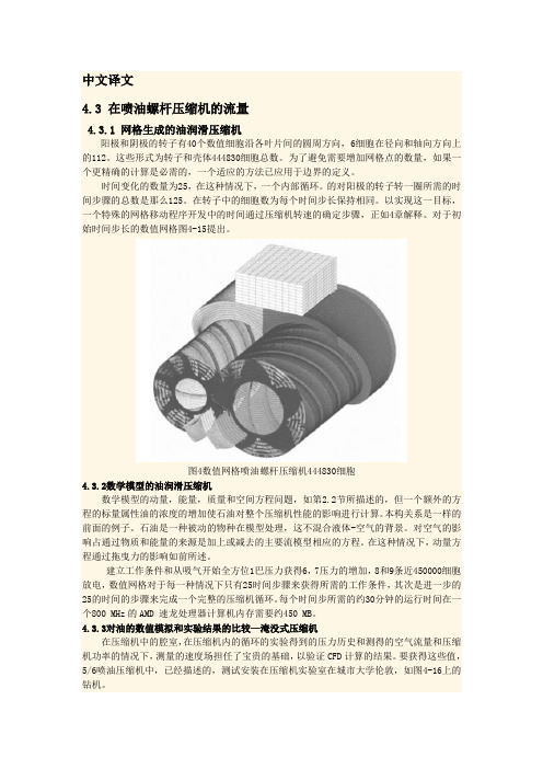
中文译文4.3 在喷油螺杆压缩机的流量4.3.1 网格生成的油润滑压缩机阳极和阴极的转子有40个数值细胞沿各叶片间的圆周方向,6细胞在径向和轴向方向上的112。
这些形式为转子和壳体444830细胞总数。
为了避免需要增加网格点的数量,如果一个更精确的计算是必需的,一个适应的方法已应用于边界的定义。
时间变化的数量为25,在这种情况下,一个内部循环。
的对阳极的转子转一圈所需的时间步骤的总数是那么125。
在转子中的细胞数为每个时间步长保持相同。
以实现这一目标,一个特殊的网格移动程序开发中的时间通过压缩机转速的确定步骤,正如4章解释。
对于初始时间步长的数值网格图4-15提出。
图4数值网格喷油螺杆压缩机444830细胞4.3.2数学模型的油润滑压缩机数学模型的动量,能量,质量和空间方程问题,如第2.2节所描述的,但一个额外的方程的标量属性油的浓度的增加使石油对整个压缩机性能的影响进行计算。
本构关系是一样的前面的例子。
石油是一种被动的物种在模型处理,这不混合液体-空气的背景。
对空气的影响占通过物质和能量的来源是加上或减去的主要流模型相应的方程。
在这种情况下,动量方程通过拖曳力的影响如前所述。
建立工作条件和从吸气开始全方位1巴压力获得6,7压力的增加,8和9条近450000细胞放电,数值网格对于每一种情况下只有25时间步骤来获得所需的工作条件,其次是进一步的25的时间的步骤来完成一个完整的压缩机循环。
每个时间步所需的约30分钟的运行时间在一个800 MHz的AMD 速龙处理器计算机内存需要约450 MB。
4.3.3对油的数值模拟和实验结果的比较—淹没式压缩机在压缩机中的腔室,在压缩机内的循环的实验得到的压力历史和测得的空气流量和压缩机功率的情况下,测量的速度场担任了宝贵的基础,以验证CFD计算的结果。
要获得这些值,5/6喷油压缩机中,已经描述的,测试安装在压缩机实验室在城市大学伦敦,如图4-16上的钻机。
4-16喷油螺杆空气压缩机5 / 6-128mm(= 90mm)在测试床4.3流的喷油螺杆压缩机该试验台满足螺杆压缩机的接受所有pneurop /程序的要求试验。
螺杆压缩机的英文翻译

摘要】双螺杆压缩机是一种比较新颖的压缩机,因其可靠性高、操作维修方便、动力平衡性好、适应性强等优点,而广泛地应用于矿山、化工、动力、冶金、建筑、机械、制冷等工业部门。
双螺杆压缩机已经超过所有工业压缩机的50 %,其市场份额超过80 %,今后其市场份额还将继续扩大。
可见,研究双螺杆压缩机具有十分重要的意义。
本课题主要是设计通用的喷油双螺杆空气压缩机,采用单边不对称摆线-销齿圆弧型型线,阴、阳转子齿数比为6:4。
设计新型转子型线,目的是使接触线长度、泄漏三角形面积和封闭余隙容积3者达到最优化设计,以进一步提高双螺杆压缩机的机械性能。
重点研究的是双螺杆压缩机的转子型线设计、几何特性、受力分析、热力学计算。
【关键词】双螺杆压缩机转子型线啮合线齿间容积[Abstract] The twin-screw compressor is a kind of newly emerging compressor. Because of its high reliability, easy repair, good balance and good adaptability etc, and widely applied to such industrial departments as mine, chemical industry, power, metallurgy, architecture, machinery, refrigeration, etc. By designing the project, the volumetric efficiency is 70%, the compressed temperature is more 80℃。
It is very important to design and research a twin-screw compressor in industrial. The project is to design a universaltwin-screw air compressor, and to adopt single side asymmetric swept line unilaterally and dowel tooth circular rotor profile. There are six lobes on the female rotor and four lobes on the male rotor. The aim of designing a new rotor profile is to optimize the contact line length, blowhole area and clearance volume. That can improve the mechanical performance of a twin-screw compressor further. The project is mainly to research a twin-screw compressor rotor profile, geometry characteristic, mechanics analysis, thermodynamics calculation[Keywords] A twin-screw compressor, rotor profile, mesh curve, tooth space volume。
螺杆式制冷压缩机的工作原理及结构
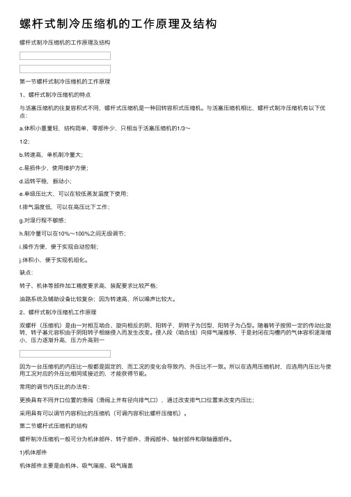
螺杆式制冷压缩机的⼯作原理及结构螺杆式制冷压缩机的⼯作原理及结构第⼀节螺杆式制冷压缩机的⼯作原理1、螺杆式制冷压缩机的特点与活塞压缩机的往复容积式不同,螺杆式压缩机是⼀种回转容积式压缩机。
与活塞压缩机相⽐,螺杆式制冷压缩机有以下优点:a.体积⼩重量轻,结构简单,零部件少,只相当于活塞压缩机的1/3~1/2;b.转速⾼,单机制冷量⼤;c.易损件少,使⽤维护⽅便;d.运转平稳,振动⼩;e.单级压⽐⼤,可以在较低蒸发温度下使⽤;f.排⽓温度低,可以在⾼压⽐下⼯作;g.对湿⾏程不敏感;h.制冷量可以在10%~100%之间⽆级调节;i.操作⽅便,便于实现⾃动控制;j.体积⼩,便于实现机组化。
缺点:转⼦、机体等部件加⼯精度要求⾼,装配要求⽐较严格;油路系统及辅助设备⽐较复杂;因为转速⾼,所以噪声⽐较⼤。
2、螺杆式制冷压缩机⼯作原理双螺杆(压缩机)是由⼀对相互啮合、旋向相反的阴、阳转⼦,阴转⼦为凹型,阳转⼦为凸型。
随着转⼦按照⼀定的传动⽐旋转,转⼦基元容积由于阴阳转⼦相继侵⼊⽽发⽣改变。
侵⼊段(啮合线)向排⽓端推移,于是封闭在沟槽内的⽓体容积逐渐缩⼩,压⼒逐渐升⾼,压⼒升⾼到⼀因为⼀台压缩机的内压⽐⼀般都是固定的,⽽⼯况的变化会导致内、外压⽐不⼀致。
所以在选⽤压缩机时,应选⽤内压⽐与使⽤⼯况对应的外压⽐相同或接近的,才能获得节能。
常⽤的调节内压⽐的办法有:更换具有不同开⼝位置的滑阀(滑阀上开有径向排⽓⼝),通过改变排⽓⼝位置来改变内压⽐;采⽤具有可以调节内容积⽐的压缩机(可调内容积⽐螺杆压缩机)。
第⼆节螺杆式压缩机的结构螺杆制冷压缩机⼀般可分为机体部件、转⼦部件、滑阀部件、轴封部件和联轴器部件。
1)机体部件机体部件主要是由机体、吸⽓端座、吸⽓端盖排⽓端座、排⽓端盖及轴封压盖等零件组成。
机体:机体内设有∞字形空腔,容纳转⼦,是压缩机的⼯作汽缸。
机体内腔上部设有径向吸⽓⼝。
机体下部有⼀部分缸壁被镗掉⽤于放置滑阀。
压缩机专业词汇中英文对照大全,你不收藏算我输!

压缩机专业词汇中英文对照大全,你不收藏算我输!中英对照压缩机分类及配件词汇容积式压缩机 positive displacement compressor往复式压缩机(活塞式压缩机) reciprocating compressor 回转式压缩机 rotary compressor滑片式压缩机 sliding vane compressor单滑片回转式压缩机 single vane rotary compressor滚动转子式压缩机 rolling rotor compressor三角转子式压缩机 triangle rotor compressor多滑片回转式压缩机 multi-vane rotary compressor滑片 blade旋转活塞式压缩机 rolling piston compressor涡旋式压缩机 scroll compressor涡旋盘 scroll固定涡旋盘 stationary scroll, fixed scroll驱动涡旋盘 driven scroll, orbiting scroll斜盘式压缩机(摇盘式压缩机) swash plate compressor 斜盘 swash plate摇盘 wobble plate螺杆式压缩机 screw compressor单螺杆压缩机 single screw compressor阴转子 female rotor阳转子 male rotor主转子 main rotor闸转子 gate rotor无油压缩机 oil free compressor膜式压缩机 diaphragm compressor活塞式压缩机 reciprocating compressor单作用压缩机 single acting compressor双作用压缩机 double acting compressor双效压缩机 dual effect compressor双缸压缩机 twin cylinder compressor闭式曲轴箱压缩机 closed crankcase compressor开式曲轴箱压缩机 open crankcase compressor顺流式压缩机 uniflow compressor逆流式压缩机 return flow compressor干活塞式压缩机 dry piston compressor双级压缩机 compound compressor多级压缩机 multistage compressor差动活塞式压缩机stepped piston compound compressor, differential piston compressor串轴式压缩机 tandem compressor, dual compressor截止阀 line valve, stop valve排气截止阀 discharge line valve吸气截止阀 suction line valve部分负荷旁通口 partial duty port能量调节器 energy regulator容量控制滑阀 capacity control slide valve容量控制器 capacity control消声器 muffler联轴节 coupling曲轴箱 crankcase曲轴箱加热器 crankcase heater轴封 crankcase seal, shaft seal填料盒 stuffing box轴封填料 shaft packing机械密封 mechanical seal波纹管密封 bellows seal转动密封 rotary seal迷宫密封 labyrinth seal轴承 bearing滑动轴承 sleeve bearing偏心环 eccentric strap滚珠轴承 ball bearing滚柱轴承 roller bearing滚针轴承 needle bearing止推轴承 thrust bearing外轴承 pedestal bearing臼形轴承 footstep bearing轴承箱 bearing housing止推盘 thrust collar偏心销 eccentric pin曲轴平衡块crankshaft counterweight, crankshaft balance weight曲柄轴 crankshaft偏心轴 eccentric type crankshaft曲拐轴 crank throw type crankshaft连杆 connecting rod连杆大头 crank pin end连杆小头 piston pin end曲轴 crankshaft主轴颈 main journal曲柄 crank arm, crank shaft曲柄销 crank pin曲拐 crank throw曲拐机构 crank-toggle阀盘 valve disc阀杆 valve stem阀座 valve seat阀板 valve plate阀盖 valve cage阀罩 valve cover阀升程限制器valve lift guard阀升程 valve lift阀孔 valve port吸气口 suction inlet压缩机气阀 compressor valve吸气阀 suction valve排气阀 delivery valve圆盘阀 disc valve环片阀 ring plate valve簧片阀 reed valve舌状阀 cantilever valve条状阀 beam valve提升阀 poppet valve菌状阀 mushroom valve杯状阀 tulip valve缸径 cylinder bore余隙容积 clearance volume附加余隙(补充余隙) clearance pocket活塞排量 swept volume, piston displacement理论排量 theoretical displacement实际排量 actual displacement实际输气量 actual displacement, actual output of gas气缸工作容积 working volume of the cylinder活塞行程容积 piston displacement气缸 cylinder气缸体 cylinder block气缸壁 cylinder wall水冷套 water cooled jacket气缸盖(气缸头) cylinder head安全盖(假盖) safety head假盖 false head活塞环 piston ring气环 sealing ring刮油环 scraper ring油环 scrape ring活塞销 piston pin活塞 piston活塞行程 piston stroke吸气行程 suction stroke膨胀行程 expansion stroke压缩行程 compression stroke排气行程 discharge stroke升压压缩机 booster compressor立式压缩机 vertical compressor卧式压缩机 horizontal compressor角度式压缩机 angular type compressor对称平衡型压缩机 symmetrically balanced type compressor 压缩机参数词汇1. performance parameter 性能参数——表征压缩机主要性能的诸参数,如:气量、压力、温度、功率及噪声、振动等2. constructional parameter 结构参数——表征压缩机结构特点的诸参数,如:活塞力、行程、转速、列数、各级缸径、外形尺寸等3. inlet pressure/suction pressure 吸气压力(吸入压力)——在标准吸气位置气体的平均绝对全压力。
中英文文献翻译-螺杆式压缩机

英文原文Screw CompressorsThe direction normal to the helicoids, can be used to calculate the coordinates of the rotorhelicoids n x and n y from x and y to which the clearance is added as:dt dyD p x x n δ+=, dt dxD p y y n δ-=, ⎪⎭⎫ ⎝⎛+=dt dy y dt dx x D z n δ (2.19) where the denominator D is given as :22222⎪⎭⎫ ⎝⎛++⎪⎭⎫ ⎝⎛+⎪⎭⎫ ⎝⎛=dt dy y dt dx x dt dy p dt dx p x D (2.20) n x and n y serve to calculate new rotor end plane coordinates, x 0n and y 0n ,with the clearances obtained for angles θ = n z /p and τ respectively. These on x and on y now serve to calculate the transverse clearance δ0 as the difference between them, as well as the original rotor coordinates o x and o y .If by any means, the rotors change their relative position, the clearance distribution at one end of the rotors may be reduced to zero on the flat side of the rotor lobes. In such a case, rotor contact will be prohibitively long on the flat side of the profile, where the dominant relative rotor motion is sliding, as shown in Fig. 2.29. This indicates that rotor seizure will almost certainly occur in that region if the rotors come into contact with each other.Fig. 2.29. Clearance distribution between the rotors: at suction, mid rotors, and discharge withpossible rotor contact at the dischargeFig. 2.30. Variable clearance distribution applied to the rotors It follows that the clearance distribution should be non-uniform to avoid hard rotor contact in rotor areas where sliding motion between the rotors is dominant.In Fig. 2.30, a reduced clearance of 65 μm is presented, which is now applied in rotor regions close to the rotor pitch circles, while in other regions it is kept at 85 μm, as was done by Edstroem, 1992. As can be seen in Fig. 2.31, the situation regarding rotor contact is now quite different. This is maintained along the rotor contact belt close to the rotor pitch circles and fully avoided at other locations. It follows that if contact occurred, it would be of a rolling character rather than a combination of rolling and sliding or even pure sliding. Such contact will not generate excessive heat and could therefore be maintained for a longer period without damaging the rotors until contact ceases or the compressor is stopped.2.6 Tools for Rotor ManufactureThis section describes the generation of formed tools for screw compressor hobbing, milling and grinding based on the envelope gearing procedure.2.6.1 Hobbing ToolsA screw compressor rotor and its formed hobbing tool are equivalent to a pair of meshing crossed helical gears with nonparallel and nonintersecting axes. Their general meshing condition is given in Appendix A. Apart from the gashes forming the cutter faces, the hob is simply a helical gear in which.Fig. 2.31. Clearance distribution between the rotors: at suction, mid of rotor and discharge with apossible rotor contact at the dischargeEach referred to as a thread, Colburne, 1987. Owing to their axes not being parallel, there is only point contact between them whereas there is line contact between the screw machine rotors. The need to satisfy the meshing equation given in Appendix A, leads to the rotor – hob meshing requirement for the given rotor transverse coordinate points 1o x and 1o y and their first derivative 0101dx dy .The hob transverse coordinate points 2o x and 2o y can then be calculated. These are sufficient to obtain the coordinate 2012012y x R +=The axial coordinate 2z , calculated directly, and 2R are hob axial plane coordinates which define the hob geometry.The transverse coordinates of the screw machine rotors, described in the previous section, are used as an example here to produce hob coordinates. he rotor unit leads 1P are 48.754mm for the main and −58.504mm for the ate rotor. Single lobe hobs are generated for unit leads 2P :6.291mm for the m ain rotor and −6.291mm for the gate rotor. The corresponding hob helix a ngles ψ are 85◦ and 95◦. The same rotor-to-hob centre distance C = 110mm a nd the shaft angle Σ = 50◦ are given for both rotors. Figure 2.32 contains a view to the hob.Reverse calculation of the hob – screw rotor transformation, also given in Appendix Apermits the determination of the transverse rotor profile coordinates which will be obtained as a result of the manufacturing process. These ay be compared with those originally specified to determine the effect ofFig. 2.32. Rotor manufacturing: hobbing tool left , right milling toolmanufacturing errors such as imperfect tool setting or tool and rotor deformation upon the final rotor profile.For the purpose of reverse transformation, the hob longitudinal plane coordinates 2R and 2z and 22dz dR should be given. The axial coordinate 2z is used to calculate 22P Z T =, which is then used to calculate the hob transverse coordinates:τcos 202R x =, τs i n 202R y = (2.21)These are then used as the given coordinates to produce a meshing criterionand the transverse plane coordinates of the “manufactured” rotors.A comparison between the original rotors and the manufactured rotors is given in Fig. 2.33 with the difference between them scaled 100 times. Two types of error are considered. The left gate rotor, is produced with 30um offset in the centre distance between the rotor and the tool, and the main rotor withFig. 2.33. Manufacturing imperfections0.2◦ of fset in the tool shaft angle Σ. Details of this particular meshing method are given by Stosic 1998.2.6.2 Milling and Grinding ToolsFormed milling and grinding tools may also be generated by placing 02=P in the general meshing equation, given in Appendix A, and then following the procedure of this section. The resulting meshing condition now reads as:[]0cot cot 1111111111=⎥⎦⎤⎢⎣⎡∂∂-∂∂+⎪⎭⎫ ⎝⎛∂∂+∂∂∑+-∑t x C t y p p t y y t x x p x C θ (2.22) However in this case, when one expects to obtain screw rotor coordinates from the tool coordinates, the singularity imposed does not permit the calculation of the tool transverse plane coordinates. The main meshing condition cannot therefore be applied. For this purpose another condition is derived for the reverse milling tool to rotor transformation from which the meshing angle τ is calculated:()0cot sin cot cos 12212222=-∑+∑++⎪⎪⎭⎫ ⎝⎛+C p dR dz C p dR dz z R ττ (2.23) Once obtained, τ will serve to calculate the rotor coordinates after the “manufacturing” process. The obtained rotor coordinates will contain all manufacturing imperfections, like mismatch of the rotor – tool centre distance, error in the rotor – tool shaft angle, axial shift of the tool or tool deformation during the process as they are input to the calculation process. A full account of this useful procedure is given by Stosic 1998.2.6.3 Quantification of Manufacturing ImperfectionsThe rotor – tool transformation is used here for milling tool profile generation. The reverse procedure is used to calculate the “manufactured” rotors. The rack generated 5-6 128mm rotors described by Stosic, 1997a are used as given profiles: x (t ) and y (t ). Then a tool – rotor transformation is used to quantify the influence of manufacturing imperfections upon the qualityof the produced rotor profile. Both, linear and angular offset were considered.Figure 2.33 presents the rotors, the main manufactured with the shaft angle offset 0.5◦and the gate with the centre distance offset 40 μm from that of the original rotors given by the dashed line on the left. On the right, the rotors are manufactured with imperfections, the main with a tool axial offset of 40 μm and the gate with a certain tool body deformation which resulted in 0.5◦offset of the relative motion angle θ. The original rotors are given by the dashed line.3Calculation of Screw Compressor Performance Screw compressor performance is governed by the interactive effects of thermodynamic and fluid flow processes and the machine geometry and thus can be calculated reliably only by their simultaneous consideration. This may be chieved by mathematical modelling in one or more dimensions. For most applications, a one dimensional model is sufficient and this is described in full. 3-D modelling is more complex and is presented here only in outline. A more detailed presentation of this will be made in a separate publication.3.1 One Dimensional Mathematical ModelThe algorithm used to describe the thermodynamic and fluid flow processes in a screw compressor is based on a mathematical model. This defines the instantaneous volume of the working chamber and its change with rotational angle or time, to which the conservation equations of energy and mass continuity are applied, together with a set of algebraic relationships used to define various phenomena related to the suction, compression and discharge of the working fluid. These form a set of simultaneous non-linear differential equations which cannot be solved in closed form.The solution of the equation set is performed numerically by means of the Runge-Kutta 4th order method, with appropriate initial and boundary conditions.The model accounts for a number of “real-life” effects, which may significantly influence the performance of a real compressor. These make it suitable for a wide range of applications and include the following:– The working fluid compressed can be any gas or liquid-gas mixture for which an equation of state and internal energy-enthalpy relation is known, i.e. any ideal or real gas or liquid-gas mixture of known properties.–The model accounts for heat transfer between the gas and the compressor rotors or its casing in a form, which though approximate, reproduces the overall effect to a good first order level of accuracy.– The model accounts for leakage of the working medium through the clearances between the two rotors and between the rotors and the stationary parts of the compressor.– The process equations and the subroutines for their solution are independent of those which define the compressor geometry. Hence, the model can be readily adapted to estimate the performance of any geometry or type of positive displacement machine.– The effects of liquid injection, including that of oil, water, or refrigerant can be accounted for during the suction, compression and discharge stages.– A set of subroutines to estimate the thermodynamic properties and changes of state of the working fluid during the entire compressor cycle of operations completes the equation set and thereby enables it to be solved.Certain assumptions had to be introduced to ensure efficient computation.These do notimpose any limitations on the model nor cause significant departures from the real processes and are as follows:– The fluid flow in the model is assumed to be quasi one-dimensional.–Kinetic energy changes of the working fluid within the working chamber are negligible compared to internal energy changes.–Gas or gas-liquid inflow to and outflow from the compressor ports is assumed to be isentropic.– Leakage flow of the fluid through the clearances is assumed to be adiabatic.3.1.1 Conservation EquationsFor Control Volume and Auxiliary RelationshipsThe working chamber of a screw machine is the space within it that contains the working fluid. This is a typical example of an open thermodynamic system in which the mass flow varies with time. This, as well as the suction and discharge plenums, can be defined by a control volume for which the differential equations of the conservation laws for energy and mass are written. These are derived in Appendix B, using Reynolds Transport Theorem.A feature of the model is the use of the non-steady flow energy equation to compute the thermodynamic and flow processes in a screw machine in terms of rotational angle or time and how these are affected by rotor profile modifications. Internal energy, rather than enthalpy, is then the derived variable. This is computationally more convenient than using enthalpy as the derived Variable since, even in the case of real fluids, it may be derived, without reference to pressure. Computation is then carried out through a series of iterative cycles until the solution converges. Pressure, which is the desired output variable, can then be derived directly from it, together with the remaining required thermodynamic properties.The following forms of the conservation equations have been employed in the model:中文翻译螺杆式压缩机几何的法线方向的螺旋,可以用来计算的坐标转子螺旋n x 和n y 的从x 和y 的间隙加入如:dt dyD p x x n δ+=, dt dxD p y y n δ-=, ⎪⎭⎫ ⎝⎛+=dt dy y dt dx x D z n δ (2.19) 其中分母D 被给定为:22222⎪⎭⎫ ⎝⎛++⎪⎭⎫ ⎝⎛+⎪⎭⎫ ⎝⎛=dt dy y dt dx x dt dy p dt dx p x D (2.20) n x ,n y 服务来计算新的转子端的平面的坐标,on x 和on y ,得到的间隙角θ =锌/ p 和τ 。
- 1、下载文档前请自行甄别文档内容的完整性,平台不提供额外的编辑、内容补充、找答案等附加服务。
- 2、"仅部分预览"的文档,不可在线预览部分如存在完整性等问题,可反馈申请退款(可完整预览的文档不适用该条件!)。
- 3、如文档侵犯您的权益,请联系客服反馈,我们会尽快为您处理(人工客服工作时间:9:00-18:30)。
附录1 The Original EnglishTHE KEY TECHNOLOGY OF DESIGN HOB FORHOBBING SCREW COMPRESSOR ROTORSWITH CUCLOID-ARC PROFILEABSTRCTThe profile of cycloid-arc screw compressor rotors is not a smooth profile; it has a tip on it. When design the hob cutter used for machining this kind of rotors, the profile of hob edge will appear separation. In this paper, the author made researches on the design theory of hob cutter for hobbing the cycloid-arc rotor with tip profile, and got the best way for design this kind of hob cutter with a separate edge. It is good practice to design the hob cutter and hob the cycloid-arc rotor according to practical design, manufacture and test.(1) INTRODUCTIONThe efficiency and reliability of screw compressor mainly depend on manufacturing technology of screw rotors. At present, the machining method of our country for machining screw rotors is milling the shortcoming of milling is low productivity and machining accuracy. Hobbing characteristic is high productivity and machining accuracy, so the machining method for hobbing instead of milling screw compressor rotors is now becoming more and more popular.Hobbing instead of milling for machining screw compressor rotors has much more advantage, but the key problem for carrying out hobbing the screw compressor rotors is that the profile of screw compressor rotors must be suited to hobbing. Our national standard profile for screw compressor rotors have no-symmetric cycloid-arc profile and symmetric are profile [1], since no-symmetric cycloid-arc profile screw compressor has much more advantage than symmetric are profile screw compressor, our national factory all adopt the former at present. The property of no-symmetriccycloid-arc profile is that the conjoint curve of profile isn’t slick curve, it has a tip on the profile, it is still a great difficult for hobbing instead of milling this kind of screw rotors in our cou ntry as the design problem of hob cutter. In this paper, we’ll make researches on the design theory of hob cutter for hobbing the no-symmetric cycloid-arc rotor with tip profile.(2 ) EXISTING PROBLEMFig.1 shows the end section of no-symmetric cycloid-arc rotors, its end profile is composed of radial line ab, arc bc, prolonged cycloid cd and radial line de. The point of intersection of prolonged cycloid cd and radial line de exist a tip d, that is, the d point of intersection hasn’t common tangent. As we calculate the corresponding axial profile of hob cutter according to cutting tool design handbook or other cutting tool design data, we’ll find that the axial profile of hob cutter becomes two separate curves, like the one shown in Fig.2.Fig.1 The end profile of screw rotor Fig.2 The axial profile of hobIn order to machining the required rotor profile and insure the tip not being cut out, people can usually take following two ways to solve this problem. One way is to prolong curve cd and radial line de as Fig.3 shows, this way can avoid appearing separate curve of hob edge, but hob profile will become Fig.4 shows, this kind of hob edge can neither be machined nor be used. Another way is to make a concave curve to link the separate hob edge as Fig.5 shows.Fig.3 The end profile of screw rotor Fig.4 The axial profile of hob Fig.5 The concave curve This way can avoid the tip being cut out, but it will produce two new tips on hob edge. This kind of hob is not only difficult to be machined but also easy to be worn on the tips. Form above discussing we can see that above two ways is not the best way to solve this problem. The best way to solve this kind of problem is to figure out the intermediate curve between separate edge curves accurately.(3) THE BEST WAY FOR CALCULATING INTERMEDIATE CURVE ACCURATELYHere we make use of the intermediate rack to calculate the intermediate curve between separate edge curves. That is, in the first place, we figure out the intermediate profile of rack according to the mesh of intermediate rack and rotor, in the second place, we figure out the intermediate profile of hob edge curve according to the mesh of intermediate rack and hob worm.According to gear mesh theorem, we can figure out the profile of intermediate rack mesh with rotor easily. As the tip exists on the profile of rotor, calculated profile of rotor will be two separate curves as Fig.2 shows. The two coordinates points d1 and d2 can easily figure out as following d1(x1, y1) and d2(x2, y2), obviously, the formation of separate curve of rack profile is that the tip d on rotor profile move around the rack to form when rack meshes with rotor. According to Fig.6 we can see, the mesh of rack and rotor is equal to pitch circle of rotor rolling on the pitch line of rack, the point d on rotor formed moving track is the intermediate curve of rack.Fig.6 The formation of separate curve on rackThe separate curve on rack can easily be given by the following equation:11sin()cos()t t x r y r θρθφρθφ=-+⎧⎨=-++⎩ (1) Where r is the pitch circle radius of rotor, ρ is the length of radial line od, Ф is the angle included between the radial line oe and the coordinate axis Y .θ is a variable, its bound is θ1≤θ≤θ2, θ1 and θ2 value can be calculated by the equation (1) according to the coordinate value of d1(x1, y1) and d2(x2, y2).As we know the separate curve equation on rack, we can figure out the separate curve equation of rack at the end of hob worm by the Fig.7 as following:1211cos /cos t t t t x x y y ββ=⎧⎨=⎩ (2) Where β1 is the spiral angle of rotor, β2 is the spiral angle of hob worm.According to gear mesh theorem [2], we can figure out the separate curve equation of hob worm mesh with the separate curve equation on rack by the Fig.7 as following:Fig.7 The common rack mesh with the rotor and the hob worm3111111311111111()cos ()sin ()cos ()sin ()//t t t t t t tt t x r x y r y y r x r y tgu x r u tg dy dx ϕϕϕϕϕϕϕ-=-+-⎧⎪=-+-⎪⎨=+⎪⎪=⎩ (3) According to formula (1), (2) and (3), we can accurately figure out the separate curve between the two separate profiles on hob edge.We can insure to hob the right profile of cycloid-arc rotor according to above formula to design the hob. It is good practice to design the hob cutter and hob the cycloid-arc rotor according to practical design, manufacture and test.4 REFERENCES[1] Li Wenling. Rotary Compressor for Refrigeration.Beijing: Mechanical Industry Press, 1992. 110~122. (in Chinese)[2] Li Rusheng. Design Principle of Cutting Tools. Nanjin: Science & Technology Press, 1985. 475~485. (in Chinese)2 中文翻译设计加工螺杆式压缩机的内摆线—弧轮廓所用滚刀的关键技术摘要螺杆式压缩机的内摆线—弧部分的轮廓并不是光滑的,它存在一个尖端。