中英文文献翻译-螺杆压缩机
机械设计制造及自动化中英文对照外文翻译文献
机械设计制造及⾃动化中英⽂对照外⽂翻译⽂献中英⽂对照外⽂翻译⽂献(⽂档含英⽂原⽂和中⽂翻译)使⽤CBN砂轮对螺杆转⼦进⾏精密磨削的⽅法摘要:针对⾼精度加⼯螺杆转⼦,这篇论⽂介绍了利⽤⽴⽅氮化硼(CBN砂轮)对螺杆转⼦进⾏精密磨削的加⼯⽅法。
⾸先,使⽤⼩型电镀CBN砂轮磨削螺杆转⼦。
精确的CBN砂轮轴向轮廓的模型是在齿轮啮合理论的基础上建⽴开发的。
考虑到螺杆转⼦和涂层厚度之间的间隙,主动砂轮的修整引⼊了CBN的砂轮的设计⽅法。
主动砂轮的形状采⽤低速电⽕花线切割技术(低速⾛丝线切割机)进⾏加⼯线CBN主动砂轮的成形车⼑采⽤低速⾛丝机切割机进⾏加⼯。
CBN螺杆转⼦砂轮采⽤本⽂提出的原理进⾏有效性和正确性的验证。
电镀CBN砂轮对螺杆转⼦进⾏加⼯,同时进⾏机械加⼯实验。
在实验中获得的数据达到GB10095-88五级认证。
关键词: CBN砂轮精密磨削螺杆转⼦砂轮外形修整专业术语⽬录:P 螺杆转⼦的参数H 螺杆转⼦的直径Σ砂轮和转⼦的安装⾓度Au 砂轮和转⼦的中⼼距8 螺旋转⼦接触点的旋转⾓x1, y1, z1:转⼦在σ系统中的位置x, y, z: 砂轮端⾯的位置x u ,y u ,z u: x, x y z轴的法向量n x ,ny,nz:X Y Z轴的端⾯法向量n u , nu, nu:砂轮的⾓速度的⽮量:砂轮模块的⾓速度wu:螺旋转⼦的⾓速度w1螺旋转⼦模块的⾓速度转⼦接触点的⾓速度转⼦表⾯接触点的初始速度砂轮表⾯接触点的⾓速度砂轮表⾯接触点的初始速度l砂轮的理论半径砂轮轴的理想位置砂轮表⾯的修改半径砂轮轴的修改位置砂轮表⾯的法向量1.引⾔螺旋转⼦是螺杆压缩机、螺钉、碎纸机以及螺杆泵的关键部分。
转⼦的加⼯精度决定了机械性能。
⼀般来说,铣⼑⽤于加⼯螺旋转⼦。
许多研究者,如肖等⼈[ 1 ]和姚等⼈[ 2 ],对⽤铣⼑加⼯螺旋转⼦做了⼤量的⼯作。
该⽅法可以提⾼加⼯效率。
然⽽,加⼯精度低和表⾯粗糙度不⾼是其主要缺点。
空压机有关结构中英文对照
空气压缩机名词英语解释时间:2010-7—1 11:40:27,点击:252容积式压缩机positive displacement compressor往复式压缩机(活塞式压缩机)reciprocating compressor回转式压缩机rotary compressor滑片式压缩机sliding vane compressor单滑片回转式压缩机single vane rotary compressor滚动转子式压缩机rolling rotor compressor三角转子式压缩机triangle rotor compressor多滑片回转式压缩机multi-vane rotary compressor滑片blade旋转活塞式压缩机rolling piston compressor涡旋式压缩机scroll compressor涡旋盘scroll固定涡旋盘stationary scroll,fixed scroll驱动涡旋盘driven scroll,orbiting scroll斜盘式压缩机(摇盘式压缩机)swash plate compressor斜盘swash plate摇盘wobble plate螺杆式压缩机screw compressor单螺杆压缩机single screw compressor阴转子female rotor阳转子male rotor主转子main rotor闸转子gate rotor无油压缩机oil free compressor膜式压缩机diaphragm compressor活塞式压缩机reciprocating compressor单作用压缩机single acting compressor双作用压缩机double acting compressor双效压缩机dual effect compressor双缸压缩机twin cylinder compressor闭式曲轴箱压缩机closed crankcase compressor开式曲轴箱压缩机open crankcase compressor顺流式压缩机uniflow compressor逆流式压缩机return flow compressor干活塞式压缩机dry piston compressor双级压缩机compound compressor多级压缩机multistage compressor差动活塞式压缩机stepped piston compound compressor, differential piston compressor 串轴式压缩机tandem compressor,dual compressor截止阀line valve, stop valve排气截止阀discharge line valve吸气截止阀suction line valve部分负荷旁通口partial duty port能量调节器energy regulator容量控制滑阀capacity control slide valve容量控制器capacity control消声器muffler联轴节coupling曲轴箱crankcase曲轴箱加热器crankcase heater轴封crankcase seal, shaft seal填料盒stuffing box轴封填料shaft packing机械密封mechanical seal波纹管密封bellows seal转动密封rotary seal迷宫密封labyrinth seal轴承bearing滑动轴承sleeve bearing偏心环eccentric strap滚珠轴承ball bearing滚柱轴承roller bearing滚针轴承needle bearing止推轴承thrust bearing外轴承pedestal bearing臼形轴承footstep bearing轴承箱bearing housing止推盘thrust collar偏心销eccentric pin曲轴平衡块crankshaft counterweight, crankshaft balance weight 曲柄轴crankshaft偏心轴eccentric type crankshaft曲拐轴crank throw type crankshaft连杆connecting rod连杆大头crank pin end连杆小头piston pin end曲轴crankshaft主轴颈main journal曲柄crank arm,crank shaft曲柄销crank pin曲拐crank throw曲拐机构crank-toggle阀盘valve disc阀杆valve stem阀座valve seat阀板valve plate阀盖valve cage阀罩valve cover阀升程限制器valve lift guard阀升程valve lift阀孔valve port吸气口suction inlet压缩机气阀compressor valve吸气阀suction valve排气阀delivery valve圆盘阀disc valve环片阀ring plate valve簧片阀reed valve舌状阀cantilever valve条状阀beam valve提升阀poppet valve菌状阀mushroom valve杯状阀tulip valve缸径cylinder bore余隙容积clearance volume附加余隙(补充余隙)clearance pocket活塞排量swept volume,piston displacement理论排量theoretical displacement实际排量actual displacement实际输气量actual displacement, actual output of gas 气缸工作容积working volume of the cylinder活塞行程容积piston displacement气缸cylinder气缸体cylinder block气缸壁cylinder wall水冷套water cooled jacket气缸盖(气缸头) cylinder head安全盖(假盖)safety head假盖false head活塞环piston ring气环sealing ring刮油环scraper ring油环scrape ring活塞销piston pin活塞piston活塞行程piston stroke吸气行程suction stroke膨胀行程expansion stroke压缩行程compression stroke排气行程discharge stroke升压压缩机booster compressor立式压缩机vertical compressor卧式压缩机horizontal compressor角度式压缩机angular type compressor对称平衡型压缩机symmetrically balanced type compressor空压机英文菜单及报警信息的中英文对照序号英文报警信息中文报警名称1 Emergencey Stop 紧急制动2 Communication Control 通讯控制3 Invalid Access Code 进入码错误4 No fault stored 无故障信息存储5 No fault reset 无复位指示6 No service indicated 无维修指示7 Remote start enable 远程启动8 Remote start enables 远程停机9 Stop machine first 先停机10 Fan motor fault 风扇电机故障11 High air pressure 空气压力过高12 High oil temp fault 油温过高13 Main motor fault 主电机故障14 Pressure probe fault 压力探测器故障15 Rotation fault 转向故障16 Star/delta fault Y/△故障17 Temperature probe fault 温度探测器故障18 Change air filter 更换空气过滤器19 Chang reclaimer element 更换油分离器滤芯20 High oil 油温过高21 Service due 技术服务时间到22 Max overpress 最高过压(自己复位)23 Total 总时数24 Hours on load 负载时数25 Max。
单螺杆型使用的是机械外文文献翻译、中英文翻译、外文翻译
中国地质大学长城学院本科毕业设计外文资料翻译系别:工程技术系专业:机械设计制造及其自动化姓名:李江学号: 052083072012 年 4 月 20 日外文资料翻译译文塑料工业是与国民经济发展和社会文明建设息息相关的重要产业。
塑料工业的机械和装备的水平对该工业的发展起着关键作用。
比起传统的塑料挤出机,单螺杆塑料挤出机有他积极的优势,通常他能加工出高分子量、高粘度热塑性好的塑料。
其中有高生产率低熔点、高熔体强压力的塑料有利于化学降解,产品质量高,品,因此是最佳的塑料生产这使得单螺杆塑料挤出机生产经济,特别适用于稳定的挤压。
螺杆的回转航程和固定筒壁的相互作用是挤出机的泵出过程中必要的参数。
为了运输塑料材料,其摩擦在螺杆的表面要低,但在固定的筒壁要高。
如果达不到这个基本标准,塑料可能会随着螺杆旋转,而不是在轴向/输出方向上移动。
在输出区域,螺杆和机筒的表面通常都覆盖着的溶解物以及来自溶解物和螺杆通道之间的外力,而其除了处理有极高粘性的材料时都是无效的,如硬质PVC 材料和有超高分子量的聚乙烯。
溶解物流在输出部分是受内摩擦系数(粘度)影响,尤其是当模具提供了一个高阻力的熔体流时。
常见且更多使用的单螺杆型使用的是传统设计,即机筒和螺杆保持基本一致的直径,包括具有例如减小螺杆通道体积,有连续可变速度、压力控制,和通风(挥发)系统的挤出机。
一些特殊的设计使用了圆锥或抛物线外形的螺杆,用以达到特殊的混合和捏合效果。
它们可以包含偏心的核心,根据不同坡度变化的动程,揉捏转子,适应性的核心环,和间歇的轴向运动。
桶内可能有螺纹,可伸缩的螺杆形状以及进料设备。
一个成功的挤出操作需要密切注意很多细节,如(1)进给材料的质量和在适当温度下的物质流,(2)足以融化、但不会分解聚合物的温度曲线,以及(3)不会分解塑料的启动和关机。
应采取措施,防止促进塑料表面上水分的胶合和湿气的吸收凝结,如颜料浓缩物中的色素。
表面凝结,可通过储存于密封的塑料容器(吸湿性塑料)中在使用前约24 小时与工作区域保持同温来避免。
螺杆压缩机性能的计算吸入室中占主导地位外文文献翻译、中英文翻译、外文翻译
英文原文3.1 One Dimensional Mathematical Model 51The Conservation of Internal Energyθωω.d dv p Q h m h m dQ du out out in in += (3.1) where θ is angle of rotation of the main rotor, h = h (θ) is specific enthalpy, m ˙ = m ˙ (θ) is mass flow rate p = p (θ), fluid pressure in the working chamber control volume, ˙Q = ˙Q (θ), heat transfer between the fluid and the compressor surrounding, ˙V = ˙V (θ) local volume of the compressor working chamber.In the above equation the subscripts in and out denote the fluid inflow and outflow. The fluid total enthalpy inflow consists of the following components:oil oil g l g l suc suv in in h m h m h m h .,,...m ++= (3.2) where subscripts l , g denote leakage gain suc, suction conditions, and oil denotes oil. The fluid total outflow enthalpy consists of:l l l l dis dis ou out h m h m h m ,,..+= (3.3) where indices l , l denote leakage loss and dis denotes the discharge conditions with m ˙ dis denoting the discharge mass flow rate of the gas contaminated with the oil or other liquid injected.The right hand side of the energy equation consists of the following terms which are model The heat exchange between the fluid and the compressor screw rotors and casing and through them to the surrounding, due to the difference in temperatures of gas and the casing and rotor surfaces is accounted for by the heat transfer coefficient evaluated from the expression Nu = 0.023 Re0.8. For the characteristic length in the Reynolds and Nusselt number the difference between the outer and inner diameters of the main rotor was adopted. This may not be the most appropriate dimension for this purpose, but the characteristic length appears in the expression for the heat transfer coefficient with the exponent of 0.2 and therefore has little influence as long as it remains within the same order of magnitude as other characteristic dimensions of the machine and as long as it characterizes the compressor size. The characteristic velocity for the Re number is computed from the local mass flow and the cross-sectional area. Here the surface over which the heat is exchanged, as well as the wall temperature, depend on the rotation angle θ of the main rotor. The energy gain due to the gas inflow into the working volume is represented by the product of the mass intake and its averaged enthalpy. As such, the energy inflow varies with the rotational angle. During the suction period, gas enters the working volume bringing the averaged gas enthalpy,52 3 Calculation of Screw Compressor Performance which dominates in the suction chamber. However, during the time when the suction port is closed, a certain amount of the compressed gas leaks into the compressor working chamber through the clearances. The mass ofthis gas, as well as its enthalpy are determined on the basis of the gas leakage equations. The working volume is filled with gas due to leakage only when the gas pressure in the space around the working volume is higher, otherwise there is no leakage, or it is in the opposite direction, i.e. from the working chamber towards other plenums.The total inflow enthalpy is further corrected by the amount of enthalpy brought into the working chamber by the injected oil.The energy loss due to the gas outflow from the working volume is defined by the product of the mass outflow and its averaged gas enthalpy. During delivery, this is the compressed gas entering the discharge plenum, while, in the case of expansion due to inappropriate discharge pressure, this is the gas which leaks through the clearances from the working volume into the neighbouring space at a lower pressure. If the pressure in the working chamber is lower than that in the discharge chamber and if the discharge port is open, the flow will be in the reverse direction, i.e. from the discharge plenum into the working chamber. The change of mass has a negative sign and its assumed enthalpy is equal to the averaged gas enthalpy in the pressure chamber.The thermodynamic work supplied to the gas during the compression process is represented by the term pdV d θ . This term is evaluated from the local pressure and local volume change rate. The latter is obtained from the relationships defining the screw kinematics which yield the instantaneous working volume and its change with rotation angle. In fact the term dV/d ϕ can be identified with the instantaneous interlobe area, corrected for the captured and overlapping areas. If oil or other fluid is injected into the working chamber of the compressor, the oil mass inflow and its enthalpy should be included in the inflow terms. In spite of the fact that the oil mass fraction in the mixture is significant, its effect upon the volume flow rate is only marginal because the oil volume fraction is usually very small. The total fluid mass outflow also includes the injected oil, the greater part of which remains mixed with the working fluid. Heat transfer between the gas and oil droplets is described by a first order differential equation. The Mass Continuity Equationout out in in h m h m d m d ...θω= (3.4) The mass inflow rate consists of:oil g l suc in in m m m h m .,..++= (3.5)3.1 One Dimensional Mathematical Model 53The mass outflow rate consists of: .,..l l dis out m m m += (3.6)Each of the mass flow rate satisfies the continuity equationA m ρω=. (3.7) where w [m/s] denotes fluid velocity, ρ – fluid density and A – the flow crosssectionarea. The instantaneous density ρ = ρ(θ) is obtained from the instantaneous mass m trapped in the control volume and the size of the corresponding instantaneous volume V , as ρ = m/V .3.1.2 Suction and Discharge PortsThe cross-section area A is obtained from the compressor geometry and it may be considered as a periodic function of the angle of rotation θ. The suction port area is defined by:⎪⎪⎭⎫ ⎝⎛=suc o suc A A θθπsin ,suc (3.8) where suc means the starting value of θ at the moment of the suction port opening, and A suc , 0 denotes the maximum value of the suction port crosssection area. The reference value of the rotation angle θ is assumed at the suction port closing so that suction ends at θ = 0, if not specified differently.The discharge port area is likewise defined by:⎪⎪⎭⎫ ⎝⎛--=s e c o dis A A θθθθπsin ,dis (3.9)where subscript e denotes the end of discharge, c denotes the end of compression and A dis , 0 stands for the maximum value of the discharge port crosssectional area.Suction and Discharge Port Fluid Velocities)(212h h -=μω (3.10)where μ is the suction/discharge orifice flow coefficient, while subscripts 1 and 2 denote the conditions downstream and upstream of the considered port. The provision supplied in the computer code will calculate for a reverse flow if h 2 < h 1.54 3 Calculation of Screw Compressor Performance3.1.3 Gas LeakagesLeakages in a screw machine amount to a substantial part of the total flow rate and therefore play an important role because they influence the process both by affecting the compressor mass flow rate or compressor delivery, i.e. volumetric efficiency and the thermodynamic efficiency of the compression work. For practical computation of the effects of leakage upon the compressor process, it is convenient to distinguish two types of leakages, according to their direction with regard to the working chamber: gain and loss leakages. The gain leakages come from the discharge plenum and from the neighbouring working chamber which has a higher pressure. The loss leakages leave the chamber towards the suction plenum and to the neighbouring chamber with a lower pressure.Computation of the leakage velocity follows from consideration of the fluid flow through the clearance. The process is essentially adiabatic Fanno-flow. In order to simplify the computation, the flow is is sometimes assumed to be at constant temperature rather than at constant enthalpy. This departure from the prevailing adiabatic conditions has only a marginal influence if the analysis is carried out in differential form, i.e. for the small changes of the rotational angle, as followed in the present model. The present model treats only gas leakage. No attempt is made to account for leakage of a gas-liquid mixture, while the effect of the oil film can be incorporated by an appropriate reduction of the clearance gaps.An idealized clearance gap is assumed to have a rectangular shape and the mass flow of leaking fluid is expressed by the continuity equation:g l l l A m ωρμ=. (3.11)where r and w are density and velocity of the leaking gas, Ag = lg δg the clearance gap cross-sectional area, lg leakage clearance length, sealing line, δg leakage clearance width or gap, μ = μ(Re, Ma) the leakage flow discharge coefficient.Four different sealing lines are distinguished in a screw compressor: the leading tip sealing line formed between the main and gate rotor forward tip and casing, the trailing tip sealing line formed between the main and gate reverse tip and casing, the front sealing line between the discharge rotor front and the housing and the interlobe sealing line between the rotors.All sealing lines have clearance gaps which form leakage areas. Additionally, the tip leakage areas are accompanied by blow-hole areas.According to the type and position of leakage clearances, five different leakages can be identified, namely: losses through the trailing tip sealing and front sealing and gains through the leading and front sealing. The fifth, “throughleakage ” does not directly affect the process in the working chamber, but it passes through it from the discharge plenum towards the suction port. The leaking gas velocity is derived from the momentum equation, which accounts for the fluid-wall friction:3.1 One Dimensional Mathematical Model 5502211=++Dg dxf dpd l ωρωω (3.12)where f (Re, Ma) is the friction coefficient which is dependent on the Reynolds and Mach numbers, Dg is the effective diameter of the clearance gap, Dg ≈ 2δg and dx is the length increment. From the continuity equation and assuming that T ≈ const to eliminate gas density in terms of pressure, the equation can be integrated in terms of pressure from the high pressure side at position 2 to the low pressure side at position 1 of the gap to yield:⎪⎪⎭⎫ ⎝⎛+-==1222122.ln 2m p p a A g l l ςρρωρ (3.13)where ζ = fLg/Dg + Σξ characterizes the leakage flow resistance, with Lg clearance length in the leaking flow direction, f friction factor and ξ local resistance coefficient. ζ can be evaluated for each clearance gap as a function of its dimensions and shape and flow characteristics. a is the speed of sound.The full procedure requires the model to include the friction and drag coefficients in terms of Reynolds and Mach numbers for each type of clearance.Likewise, the working fluid friction losses can also be defined in terms of the local friction factor and fluid velocity related to the tip speed, density, and elementary friction area. At present the model employs the value of ζ in terms of a simple function for each particular compressor type and use. It is determined as an input parameter.These equations are incorporated into the model of the compressor and employed to compute the leakage flow rate for each clearance gap at the local rotation angle θ.3.1.4 Oil or Liquid InjectionInjection of oil or other liquids for lubrication, cooling or sealing purposes, modifies the thermodynamic process in a screw compressor substantially. The following paragraph outlines a procedure for accounting for the effects of oil injection. The same procedure can be applied to treat the injection of any other liquid. Special effects, such as gas or its condensate mixing and dissolving in the injected fluid or vice versa should be accounted for separately if they are expected to affect the process. A procedure for incorporating these phenomena into the model will be outlined later.A convenient parameter to define the injected oil mass flow is the oil-to-gas mass ratio, m oil /m gas, from which the oil inflow through the open oil port, which is assumed to be uniformly distributed, can be evaluated asπ21....z m m m m gas oiloil = (3.14) where the oil-to-gas mass ratio is specified in advance as an input parameter56 3 Calculation of Screw Compressor PerformanceIn addition to lubrication, the major purpose for injecting oil into a compressor is to cool the gas. To enhance the cooling efficiency the oil is atomized into a spray of fine droplets by means of which the contact surface between the gas and the oil is increased. The atomization is performed by using specially designed nozzles or by simple high-pressure injection. The distribution of droplet sizes can be defined in terms of oil-gas mass flow and velocity ratio for a given oil-injection system. Further, the destination of each distinct size of oil droplets can be followed until it hits the rotor or casing wall by solving the dynamic equation for each droplet size in a Lagrangian frame, accounting for inertia gravity, drag, and other forces. The solution of the droplet energy equation in parallel with the momentum equation should yield the amount of heat exchange with the surrounding gas.In the present model, a simpler procedure is adopted in which the heat exchange with the gas is determined from the differential equation for the instantaneous heat transfer between the surrounding gas and an oil droplet. Assuming that the droplets retain a spherical form, with a prescribed Sauter mean droplet diameter dS , the heat exchange between the droplet and the gas can be expressed in terms of a simple cooling law Qo = hoAo (T gas − T oil), where Ao is the droplet surface, Ao = d 2 S π, dS is the Sauter mean diameter of the droplet and ho is the heat transfer coefficient on the droplet surface, determined from an empirical expression. The exchanged heat must balance the rate of change of heat taken or given away by the droplet per unit time, Qo = moc oil dTo/dt = moc oil ωdTo/d θ, where c oil is the oil specific heat and the subscript o denotes oil droplet. The rate of change of oil droplet temperature can now be expressed as:()oilo o gas o c m T T A h d dT ωθ-=00 (3.15) The heat transfer coefficient ho is obtained from:33.06.0Pr Re 6.02u +=N (3.16)Integration of the equation in two time/angle steps yields the new oil droplet temperature at each new time/angle step:k kT T T po gas o +-=1, (3.17)where To,p is the oil droplet temperature at the previous time step and k is the non-dimensional time constant of the droplet, k = τ/Δt = ωτ/Δθ, with τ = moc oil /hoAo being the real time constant of the droplet. For the given Sauter mean diameter, dS , the non-dimensional time constant takes the formθωθω∆=∆=o oil S O o oil o h c d A h c m k 6 (3.18) The derived droplet temperature is further assumed to represent the average temperature of the oil, i.e. T oil ≈ To , which is further used to compute the enthalpy of the gas-oil mixture.3.1 One Dimensional Mathematical Model 57The above approach is based on the assumption that the oil-droplet time constant τ is smaller than the droplet travelling time through the gas before it hits the rotor or casing wall, or reaches the compressor discharge port. This means that heat exchange is completed within the droplet travelling time through the gas during compression. This prerequisite is fulfilled by atomization of the injected oil. This produces sufficiently small droplet sizes to gives a small droplet time constant by choosing an adequate nozzle angle, and, to some extent, the initial oil spray velocity. The droplet trajectory computed independently on the basis of the solution of droplet momentum equation for different droplet mean diameters and initial velocities. Indications are that for most screw compressors currently in use, except, perhaps for the smallest ones, with typical tip speeds of between 20 and 50m/s, this condition is well satisfied for oil droplets with diameters below 50 μm. For more details refer to Stosic et al., 1992.Because the inclusion of a complete model of droplet dynamics would complicate the computer code and the outcome would always be dependant on the design and angle of the oil injection nozzle, the present computation code uses the above described simplified approach. This was found to be fully satisfactory for a range of different compressors. The input parameter is only the mean Sauter diameter of the oil droplets, dS and the oil properties – density, viscosity and specific heat.3.1.5 Computation of Fluid PropertiesIn an ideal gas, the internal thermal energy of the gas-oil mixture is given by:()()()()oil oil gasoil gas mcT pV mcT mRT mu mu T +-=+-=+=11γγ (3.19)where R is the gas constant and γ is adiabatic exponentHence, the pressure or temperature of the fluid in the compressor working chamber can be explicitly calculated by input of the equation for the oil temperature T oil:()()()()()oilOIL mc mR k mcT U k T ++-+-=111γ (3.20) If k tends 0, i.e. for high heat transfer coefficients or small oil droplet size, the oil temperature fast approaches the gas temperature.In the case of a real gas the situation is more complex, because the temperature and pressure can not be calculated explicitly. However, since the internal energy can be expressed as a function of the temperature and specific volume only, the calculation procedure can be simplified by employing the internal energy as a dependent variable instead of enthalpy, as often is the practice. The equation of state p = f 1(T,V ) and the equation for specific internal energy u = f 2(T,V ) are usually decoupled. Hence, the temperature can be calculated from the known specific internal energy and the specific volume obtained from the solution of differential equations, whereas the pressure中文译文33.1一维数学模型 51内部能量守恒θωω.d dv p Q h m h m dQ du out out in in += (3.1) 其中θ是角度的旋转的主旋翼h =h ( θ )的比焓,m ˙ =m ˙ ( θ )是质量流率p = ( θ ) ,工作腔的控制体积中的流体压力, ˙ Q = Q˙( θ )的流体之间的热传递和压缩机周围, ˙ V = ˙V ( θ ) ,压缩机工作腔中的本地卷。
阀门术语中英文对照
容积式压缩机positive displacement compressor往复式压缩机(活塞式压缩机)reciprocating compressor回转式压缩机rotary compressor滑片式压缩机sliding vane compressor单滑片回转式压缩机single vane rotary compressor滚动转子式压缩机rolling rotor compressor三角转子式压缩机triangle rotor compressor多滑片回转式压缩机multi-vane rotary compressor滑片blade旋转活塞式压缩机rolling piston compressor涡旋式压缩机scroll compressor涡旋盘scroll固定涡旋盘stationary scroll, fixed scroll驱动涡旋盘driven scroll, orbiting scroll斜盘式压缩机(摇盘式压缩机)swash plate compressor斜盘swash plate摇盘wobble plate螺杆式压缩机screw compressor单螺杆压缩机single screw compressor阴转子female rotor阳转子male rotor主转子main rotor闸转子gate rotor无油压缩机oil free compressor膜式压缩机diaphragm compressor活塞式压缩机reciprocating compressor单作用压缩机single acting compressor双作用压缩机double acting compressor双效压缩机dual effect compressor双缸压缩机twin cylinder compressor闭式曲轴箱压缩机closed crankcase compressor开式曲轴箱压缩机open crankcase compressor顺流式压缩机uniflow compressor逆流式压缩机return flow compressor干活塞式压缩机dry piston compressor双级压缩机compound compressor多级压缩机multistage compressor差动活塞式压缩机stepped piston compound compressor, differential piston compressor 串轴式压缩机tandem compressor, dual compressor截止阀line valve, stop valve排气截止阀discharge line valve吸气截止阀suction line valve部分负荷旁通口partial duty port能量调节器energy regulator容量控制滑阀capacity control slide valve容量控制器capacity control消声器muffler联轴节coupling曲轴箱crankcase曲轴箱加热器crankcase heater轴封crankcase seal, shaft seal填料盒stuffing box轴封填料shaft packing机械密封mechanical seal波纹管密封bellows seal转动密封rotary seal迷宫密封labyrinth seal轴承bearing滑动轴承sleeve bearing偏心环eccentric strap滚珠轴承ball bearing滚柱轴承roller bearing滚针轴承needle bearing止推轴承thrust bearing外轴承pedestal bearing臼形轴承footstep bearing轴承箱bearing housing止推盘thrust collar偏心销eccentric pin曲轴平衡块crankshaft counterweight, crankshaft balance weight 曲柄轴crankshaft偏心轴eccentric type crankshaft曲拐轴crank throw type crankshaft连杆connecting rod连杆大头crank pin end连杆小头piston pin end曲轴crankshaft主轴颈main journal曲柄crank arm, crank shaft曲柄销crank pin曲拐crank throw曲拐机构crank-toggle阀盘valve disc阀杆valve stem阀座valve seat阀板valve plate阀盖valve cage阀罩valve cover阀升程限制器valve lift guard阀升程valve lift阀孔valve port吸气口suction inlet压缩机气阀compressor valve吸气阀suction valve排气阀delivery valve圆盘阀disc valve环片阀ring plate valve簧片阀reed valve舌状阀cantilever valve条状阀beam valve提升阀poppet valve菌状阀mushroom valve杯状阀tulip valve缸径cylinder bore余隙容积clearance volume附加余隙(补充余隙)clearance pocket活塞排量swept volume, piston displacement理论排量theoretical displacement实际排量actual displacement实际输气量actual displacement, actual output of gas 气缸工作容积working volume of the cylinder活塞行程容积piston displacement气缸cylinder气缸体cylinder block气缸壁cylinder wall水冷套water cooled jacket气缸盖(气缸头)cylinder head安全盖(假盖)safety head假盖false head活塞环piston ring气环sealing ring刮油环scraper ring油环scrape ring活塞销piston pin活塞piston活塞行程piston stroke吸气行程suction stroke膨胀行程expansion stroke压缩行程compression stroke排气行程discharge stroke升压压缩机booster compressor立式压缩机vertical compressor卧式压缩机horizontal compressor角度式压缩机angular type compressor对称平衡型压缩机symmetrically balanced type compressor CQ螺纹球阀CQ Thread Ball ValvesL形三通式L-pattern three wayT形三通式T-pattern three way安全阀Safety valve暗杆闸阀Inside screw nonrising stem type gate valve百叶窗;闸板shutter百叶窗式挡板louver damper摆阀式活塞泵swing gate piston pump保温式Steam jacket type报警阀alarm valve报警阀;信号阀;脉冲阀sentinel valve背压调节阀back pressure regulating valve背压率Rate of back pressuec本体阀杆密封body stem seal波纹管阀Bellows valves波纹管密封阀bellow sealed valve波纹管密封式Bellows seal type波纹管平衡式安全阀Bellows seal balance safety valve波纹管式减压阀Bellows reducing valve波纹管式减压阀Bellows weal reducing valve薄膜thin film薄膜;隔膜diaphragm薄膜式减压阀Diapjragm reducing valve薄型闸阀Thin Gate Valves不封闭式Unseal type槽车球阀Tank Lorry Ball Valves颤振Flutter常闭式Normally closed type常开式Normally open type超低温阀门Cryogenic valve超高压阀门Super high pressure valve超过压力Overpressure of a safety valve衬胶隔膜阀rubber lined diaphragm衬胶截止阀rubber lined globe valve垂直板式蝶阀Vertical disc type butterfly valve磁耦合截止阀Magnetic Co-operate Globe Valves带补充载荷的安全阀Supplementary loaded safety valve带辅助装置的安全阀Assisted safety valve单阀碟双面平行密封闸阀parallel single disk gate valve单口排气阀Single Opening Exhaust Valves单向阀Non-return Valve单闸板Single gate disc单闸板平板闸阀Single Disc Flat Gate Valves弹簧薄膜式减压阀Spring diaphragm reducing valve弹簧式安全阀Direct spring loaded safety valve弹簧座Spring plate弹性闸板Flexible gate disc当量计算排量Equivalent calculated capacity挡板damper导阀Pilot valve导向套Valve guide disc guide低温阀门Sub-zero valve低压阀门Low pressure valve底阀bottom valve底阀Foot valve电磁动装置Eletro magnetic actuator电磁阀magnetic valve电磁阀solenoid valve电磁-液动装置Eletro magnetichydraulic actuator电动阀mortor operated valve电动阀motorized valve电动截止阀Electric Actuated Stop Valves电动平行式双闸板闸板Electric Double Disk Parallel Gate Valves 电动楔式闸阀Electric Actuated Wedge Gate Valves电动装置Electric actuator电-液动装置Eletro hydraulic actuator电液伺服阀electro-hydraulic servovalve调节弹簧Regulation spring调节阀adjusting valve调节阀control valve调节阀regulating valve调节螺套Adjusting bolt Adjusting screw调节圈Adjusting ring蝶板Disc蝶阀;瓣阀butterfly valve蝶阀;瓣阀;拍门;铰链阀flap valve蝶式缓冲止回阀Butterfly Type Non-slam Check蝶式止回阀Butterfly swing check valve定比减压阀Proprutioning pressure reducing valve定差减压阀Fixed differential reducing valve定值减压阀Fixed pressure reducing valve动态特性Dynamic characteristics对焊连接阀Buttwelding valves对夹蝶板阀Wafer plate valves对夹式衬胶蝶阀Wafer Type Butterfly Valves with Rubber Itning对夹式阀门Clamp valves对夹式止回阀Wafer Check Valves额定排量Certified capacity额定排量系数Derated coefficient of discharge 二通阀Two-way valves阀valve阀板valve deck plate阀板valve plate阀板式活塞泵valve deck plate type piston pump 阀板式活塞泵valve plate type piston pump阀瓣Disc阀操纵杆valve operating rod阀痤槽valve seat recess阀挡valve grid阀挡valve positioner阀挡valve stop阀导杆valve tail rod阀导向器valve guide阀盖bonnet阀盖衬套bonnet bush阀盖垫片bonnet gasket阀杆stem阀杆valve rod阀杆valve spindle阀杆端部尺寸Dimmension of valve stem end阀杆环stem ring阀杆螺母Yoke bushing Yoke nut阀杆填料stem packing阀杆头部尺寸Dimension of valve stem head阀簧valve spring阀簧压板valve spring plate阀控水锤泵valve-controlled hydraulic ram阀框架valve yoke阀门Valve阀门传动装置valve bandle set阀门和管件Valves and Fittings阀门盘根valve packing阀门手柄valve handle阀盘disc阀盘valve disc阀片Disc阀球valve ball阀驱动臂valve driving arm阀驱动臂valve motion arm阀式活塞valve type piston阀式活塞valve type bucket阀室式活塞泵valve box type piston pump阀室式活塞泵(美)valve pot type piston pump阀抬起装置valve lifting device阀体body阀体valve body阀箱valve box阀箱valve cage阀箱valve chest阀箱;阀限位器valve guard阀箱盖cover for valve box阀箱盖valve box cover阀箱式活塞泵(美)turret type piston pump阀形活塞泵valve type piston pump阀座Seat ring阀座valve carrier阀座valve seat(body seat)阀座;阀盘valve seat阀座环seat ring阀座密封嵌条sealing strip for valve seat法兰flange法兰堵头blind flange法兰端flange end法兰接头flange joint法兰连接紧固件(双头螺栓和螺帽)flange bolting 法兰密封面,法兰面flange facing法兰面加工flange facing finish法兰球阀Flange Ball Valves翻板阀Flap反冲盘Disc holder反向作用式减压阀Reverse acting reducing valve反向作用式减压阀Reverse acting reducing valve放空阀emptying valve放气阀air vent valve;vent valve放气阀;排气阀air evacuation valve放泄阀escape valve分置阀室式活塞泵separate valve box type piston pump 分置阀室式活塞泵(美)side pot type piston pump封闭式Seal type浮动式球阀Float ball valve浮球Ball float浮球阀Float Valve阀门种类中英文对照中文英文中文英文阀门valve 通用阀门General valve球阀Ball valve 槽车球阀Tank Lorry Ball ValvesCQ 螺纹球阀CQ Thread Ball Valves 法兰球阀Flange Ball Valves衬里球阀Lining Ball Valves API球阀API Ball valves浮动球阀Float Ball valves 固定球阀Trunnion-mounted Ball valves三通法兰球阀Three Ball valves V 型调节球阀V-Regulating Ball valves闸阀Gate valve 楔式闸阀Wedge Gate Valves法兰闸阀Flange Gate Valves 排渣闸阀Scum Gate V alves薄型闸阀Thin Gate Valves 水封闸阀Water Seal Gate Valves电动楔式闸阀Electric Actuated Wedge Gate Valves 平板闸阀Flat Gate Valve单闸板平板闸阀Single Disc Flat Gate Valves 电动平行式双闸板闸阀Electric Double Disk Parallel Gate Valves双闸板平板闸阀Double Disc Flat Gate Valves 明杆平行式双闸板闸阀Double Disk Parallel Gate Valves截止阀Globe valve 角式截止阀Angle Globe valves门角式截止阀Angle Type Globe V alves 电动截止阀Electric Actuated Stop V alves法兰截止阀Flange Globe Valves 衬里截止阀Lining Globe V alves直流式截止阀Oblique Stop Valves 柱塞截止阀Plunger Globe Valves止回阀Check valve 旋启式止回阀Swing Check Valves对夹式止回阀Wafer Check Valves 蝶式缓冲止回阀Butterfly Type Non-slam Check蝶式缓冲止回阀Butterfly Type Non-slam Check 升降式止回阀Lift Check Valves衬里止回阀Lining Check Valves 微阻缓闭止回阀Tiny Drag Slow Shut Check V alves立式止回阀Vertical Lift Check Valves蝶阀Butterfly Valve 对夹蝶板阀Wafer plate valve衬里蝶阀Lining Butterfly Valves 蜗轮传动蝶阀Butterfly Valves with Gear Actuator对夹式衬胶蝶阀Wafer Type Butterfly Valves with Rubber Itning 金属密封蝶阀Hard Seal Butterfly Valves隔膜阀diaphragm valve 旋塞阀plug valve安全阀safety valve 管道安全阀Piping Safety Valves回转阀rotary valve 减压阀pressure reducing valve减速阀Deceleration valves 泄压阀Decompression valves蒸汽疏水阀Automatic steam trap valve 组合阀Combination valves针形阀Pintle valve 仪表阀Gauge Valves仪表针形截止阀Meter Needle Type Globe Valves 空气阀门Air valves排灰阀Ash valves 吸(抽)气阀Aspirating valves辅助(副)阀Auxiliary valves 平衡阀Balance valves波纹管阀Bellows valves 泄料(放空,排污)阀Blowdown valves制动阀Brake valves 对焊连接阀Buttwelding valves地下管道阀Culvert valves 双口排气球Double Opening Exhaust Valves排水阀Drainage valves 紧急切断阀Emergeny Cut-off Valves排气阀Exhaust valves 浮球式疏水阀Free Float Type Steam Trap手动阀Hand-operated valves 液压继动阀Hydraulic relay valves限位阀Limit valves 衬里三通旋塞阀Lining T-Cock Valves 液位计Liquid Indicator 浆液阀Parallel Slide Valves柱塞阀Plunger valves 压力(増压)阀Pressure valve快速排污阀Quick Draining Valves 电磁阀Solenoid valves 过滤器Strainer 节流阀Throttle Valves阀门术语中英文对照中文英文口径bore公称通径Nominal diameter公称压力Nominal pressure工作温度Operating temperature工作压差Operating pressure工作背压Operating back pressure关闭压力Lockup pressure开启高度Lift壳体试验Shell test壳体试验压力Seal test pressure连接尺寸Conncetion cimension连接形式Type of connection流道面积Flow area流道直径Flow diameter流量孔板flow orifice plate流量特性Flow characteristics流量特性偏差Flow characteristics derivation漏汽量Steam loss密封面Sealing face密封试验Seal test密封试验压力Seal test pressure上密封Back seat上密封试验Back seal test适用介质Suitable medium适用温度Suitable temperature最大过冷度Maximum subcoold temperature最大流量Maximum flow rate最大压差Maximum differential pressure最低工作压力Minimum operating pressure最高背压率Maximum rate of back pressure最高允许压力Maximum allowable pressure最小过冷度Minimum subcooled temperature最小压差Minimum differntial pressure常闭式Normally closed type常开式Normally open type阀门零配件中英文对照中文英文阀体body阀盖bonnet阀盖垫片bonnet gasket阀盖衬套bonnet bush阀瓣Disc阀箱valve box阀座Seat ring阀杆Stem阀杆螺母Yoke bushing Yoke nut 法兰flange填料Packing填料垫Packing seat密封件Sealing挡板damper导向套Valve guide disc guide弹簧座Spring plate轴套Axis Guide球、球芯Ball密封圈Ball seat螺母Mut螺栓Screw弹簧Spring闸板Wedge Disc。
螺杆压缩机机械外文文献翻译、中英文翻译、外文翻译
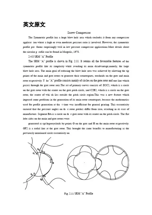
英文原文Screw CompressorThe Symmetric profile has a huge blow-hole area which excludes it from any compressor applicat -ion where a high or even moderate pressure ratio is involved. However, the symmetric profile per -forms surprisingly well in low pressure compressor applications.More details about the circular p -rofile can be found in Margolis, 1978.2.4.8 SRM “A” ProfileThe SRM “A” profile is shown in Fig. 2.11. It retains all the favourable features of the symmetric profile like its simplicity while avoiding its main disadvantage,namely, the large blow-hole area. The main goal of reducing the blow hole area was achieved by allowing the tip points of the main and gate rotors to generate their counterparts, trochoids on the gate and main rotor respectively. T -he “A” profile consists mainly of circles on the gate rotor and one line which passes through the gate rotor axis.The set of primary curves consists of: D2C2, which is a circle on the gate rotor with the centre on the gate pitch circle, and C2B2, which is a circle on the gate rotor, the centre of whi ch lies outside the pitch circle region.This was a new feature which imposed some problems in the generation of its main rotor counterpart, because the mathematics used for profile generation at tha -t time was insufficient for general gearing. This eccentricity ensured that the pressure angles on th -e rotor pitches differ from zero, resulting in its ease of manufacture. Segment BA is a circle on th -e gate rotor with its centre on the pitch circle. The flat lobe sides on the main and gate rotors weregenerated as epi/hypocycloids by points G on the gate and H on the main rotor respectively. GF2 is a radial line at the gate rotor. This brought the same benefits to manufacturing as the previously mentioned circle eccentricity onFig. 2.11 SRM “A” Profile2.4 Review of Most Popular Rotor Profiles 31 the opposite lobe side. F2E2 is a circle with the cent -re on the gate pitch and finally, E2D2 is a circle with the centre on the gate axis.More details on t -he “A” profile are published by Amosov et al., 1977 and by Rinder, 1979.The “A” profile is a go od example of how a good and simple idea evolved into a complicated result. Thus the “A” pro file was continuously subjected to changes which resulted in the “C” profile. This was mainly gen erated to improve the profile manufacturability. Finally, a completely new profile, the“D” profile was generated to introduce a new development in profile gearing and to increase the gate rotor tor -que.Despite the complexity o f its final form the “A” profile emerged to be the most popular scre -w compressor profile, especially after its patent expired.2.4.9 SRM “D” ProfileThe SRM “D” profile, shown in Fig. 2.12, is generated exclusively by circles with the centres off the rotor pitch circles.Similar to the Demonstrator, C2D2 is an eccentric circle of radius r3 onthe gate rotor. B1C1 is an eccentric circle of radius r1, which, together withthe small circular arc A1J1 of radius r2, is positioned on the main rotor. G2H2is a small circular arc on the gate rotor and E2F2 is a circular arc on the gaterotor. F2G2 is a relatively large circular arc on the gate rotor which produces a corresponding curve of the smallest possible curvature on the main rotor.Both circular arc, B2C2 and F2G2 ensure a large radius of curvature in the pitch circle area. This avoids high stresses in the rotor contact region.Fig. 2.12 SRM “D” ProfileThe “G” profile was introduced by SRM in the late nineteen nineties as a replacement for the “D” rotor and is shown in Fig. 2.13. Compared with the“D” rotor, the “G” rotor has the unique feature of two additional circles in the addendum area on both lobes of the main rotor, close to the pitch circle.This feature improves the rotor contact and, additionally, generates shorter sealing lines. This can be seen in Fig. 2.13, where a rotor featuring “G” profile characteristics only on its flat side through segment H1I1 is presented.Fig. 2.13 SRM “G” Profile2.4.11 City “N” Rack Generated Rotor Profile“N” rotors are calculated by a rack generation procedure. This distinguishes them from any others. In this case, the large blow-hole area, which is a characteristic of rack generated rotors, is overcome by generating the high pressure side of the rack by means of a rotor conjugate procedure. This undercuts the single appropriate curve on the rack. Such a rack is then used for profiling both the main and the gate rotors. The method and its extensions were used by the authors to create a number of different rotor profiles, some of them used by Stosic et al., 1986, and Hanjalic and Stosic, 1994. One of the applications of the rack generation procedure is described in Stosic, 1996.The following is a brief description of a rack generated “N” rotor profile,typical of a family of rotor profiles designed for the efficient compression of air,common refrigerants and a number of process gases. The rotors are generated by the combined rack-rotor generation procedure whose features are such that it may be readily modified further to optimize performance for any specific application.2.4 Review of Most Popular Rotor Profiles 33The coordinates of all primary arcs on the rack are summarized here relative to the rack coordinate system. The lobe of the rack is divided into several arcs. The divisions between the profile arcs are denoted by capital letters and each arc is defined separately, as shown in the Figs.2.14 and 2.15 where the rack and the rotors are shown.Fig. 2.14 Rack generated “N” ProfileFig. 2.15 “N” rotor primary curves g iven on rack34 2 Screw Compressor GeometryAll curves are given as a “general arc” expressed as: axp + byq = 1. Thus straight lines, circles, parabolae, ellipses and hyperbolae are all easily described by selecting appropriate values for parameters a, b, p and q.Segment DE is a straight line on the rack, EF is a circular arc of radius r4,segment FG is a straight line for the upper involute, p = q = 1, while segment GH on the rack is a meshing curve generated by the circular arc G2H2 on the gate rotor. Segment HJ on the rack is a meshing curve generated by the circular arc H1J1 of radius r2 on the main rotor. Segment JA is a circular arc of radius r on the rack, AB is an arc which can be either a circle or a parabola, a hyperbola or an ellipse, segment BC is a straight line on the rack matching the involute on the rotor round lobe and CD is a circular arc on the rack, radius r3.More details of the “N” profile can be found in Stosic, 1994.2.4.12 Characteristics of “N” ProfileSample illustrations of the “N” profile in 2-3, 3-5, 4-5, 4-6, 5-6, 5-7 and 6-7 configurations are given in Figs. 2.16 to Fig. 2.23. It should be noted that all rotors considered were obtained automatically from a computer code by simply specifying the number of lobes in the main and gate rotors, and the lobe curves in the general form.A variety of modified profiles is possible. The “N” profile design is a compromise between full tightness, small blow-hole area, large displacement.Fig. 2.16 “N” Rotors in 2-3 configurationFig. 2.17 “N” Rotors in 3-5 configurationFig. 2.18 “N” Rotors in 4-5 configurationFig. 2.19 “N” Rotors in 4-6 configurationFig. 2.20 “N” Rotors compared with “Sigma”, SRM “D” and “Cyclon” rotorsFig. 2.21 “N” Rotors in 5-6 configurationFig. 2.22 “N” Rotors in 5-7 configurationFig. 2.23 “N” rotors in 6/7 configurationsealing lines, small confined volumes, involute rotor contact and proper gate rotor torque distribution together with high rotor mechanical rigidity.The number of lobes required varies according to the designated compressor duty. The 3/5 arrangement is most suited for dry air compression, the 4/5 and 5/6 for oil flooded compressors with a moderate pressure difference and the 6/7 for high pressure and large built-in volume ratio refrigeration applications.Although the full evaluation of a rotor profile requires more than just a geometric assessment, some of the key features of the “N” profile may be readily appreciated by comparing it with three of the most popular screw rotor profiles already described here, (a) The “Sigma” profile by Bammert,1979, (b) the SRM “D” profile by Astberg 1982, and (c) the “Cyclon” profile by Hough and Morris, 1984. All these rotors are shown in Fig. 2.20 where it can be seen that the “N” profiles have a grea ter throughput and a stiffer gate rotor for all cases when other characteristics such as the blow-hole area, confined volume and high pressure sealing line lengths are identical.Also, the low pressure sealing lines are shorter, but this is less important because the corresponding clearance can be kept small.The blow-hole area may be controlled by adjustment of the tip radii on both the main and gate rotors and also by making the gate outer diameter equal to or less than the pitch diameter. Also the sealing lines can be kept very short by constructing most of the rotor profile from circles whose centres are close to the pitch circle. But, any decrease in the blow-hole area will increasethe length of the sealing line on the flat rotor side. A compromise betweenthese trends is therefore required to obtain the best result.2.4 Review of Most Popular Rotor Profiles 39Rotor instability is often caused by the torque distribution in the gate rotor changing direction during a complete cycle. The profile generation procedure described in this paper makes itpossible to control the torque on the gate rotor and thus avoid such effects. Furthermore, full involute contact between the “N” rotors enables any additional contact load to be absorbed more easily than with any other type of rotor. Two rotor pairs are shown in Fig. 2.24 the first exhibits what is described as “negative” gate rotor torque while the second shows the more usual “positive” torque.Fig. 2.24 “N” with negative torque, left and positive torque, right2.4.13 Blower Rotor ProfileThe blower profile, shown in Fig. 2.25 is symmetrical. Therefore only one quarter of it needs to be specified in order to define the whole rotor. It consists of two segments, a very small circle on the rotor lobe tip and a straight line. The circle slides and generates cycloids, while the straight line generates involutes.Fig. 2.25 Blower profile中文译文螺杆压缩机螺杆压缩机的几何形状对称分布有一个巨大的吹孔面积不包括它任何压缩机应用在高或中等压力比参与。
喷油螺杆压缩机的流量分析外文文献翻译、中英文翻译、外文翻译
中文译文4.3 在喷油螺杆压缩机的流量4.3.1 网格生成的油润滑压缩机阳极和阴极的转子有40个数值细胞沿各叶片间的圆周方向,6细胞在径向和轴向方向上的112。
这些形式为转子和壳体444830细胞总数。
为了避免需要增加网格点的数量,如果一个更精确的计算是必需的,一个适应的方法已应用于边界的定义。
时间变化的数量为25,在这种情况下,一个内部循环。
的对阳极的转子转一圈所需的时间步骤的总数是那么125。
在转子中的细胞数为每个时间步长保持相同。
以实现这一目标,一个特殊的网格移动程序开发中的时间通过压缩机转速的确定步骤,正如4章解释。
对于初始时间步长的数值网格图4-15提出。
图4数值网格喷油螺杆压缩机444830细胞4.3.2数学模型的油润滑压缩机数学模型的动量,能量,质量和空间方程问题,如第2.2节所描述的,但一个额外的方程的标量属性油的浓度的增加使石油对整个压缩机性能的影响进行计算。
本构关系是一样的前面的例子。
石油是一种被动的物种在模型处理,这不混合液体-空气的背景。
对空气的影响占通过物质和能量的来源是加上或减去的主要流模型相应的方程。
在这种情况下,动量方程通过拖曳力的影响如前所述。
建立工作条件和从吸气开始全方位1巴压力获得6,7压力的增加,8和9条近450000细胞放电,数值网格对于每一种情况下只有25时间步骤来获得所需的工作条件,其次是进一步的25的时间的步骤来完成一个完整的压缩机循环。
每个时间步所需的约30分钟的运行时间在一个800 MHz的AMD 速龙处理器计算机内存需要约450 MB。
4.3.3对油的数值模拟和实验结果的比较—淹没式压缩机在压缩机中的腔室,在压缩机内的循环的实验得到的压力历史和测得的空气流量和压缩机功率的情况下,测量的速度场担任了宝贵的基础,以验证CFD计算的结果。
要获得这些值,5/6喷油压缩机中,已经描述的,测试安装在压缩机实验室在城市大学伦敦,如图4-16上的钻机。
4-16喷油螺杆空气压缩机5 / 6-128mm(= 90mm)在测试床4.3流的喷油螺杆压缩机该试验台满足螺杆压缩机的接受所有pneurop /程序的要求试验。
压榨机文献翻译
单螺杆挤压数字模拟Raman V. Chiruvella Y. Jaluria” & Mukund V. Karwe罗格斯大学机械和航空航天工程学系美国,新泽西州08903,新不伦瑞克罗格斯大学食品科学系收稿于1904年7月29日,于修订1995年10月10日;接受于2月9日1996摘要我们提出了一种数字化研究淀粉基材料在单螺杆挤出机中的挤压制作。
低水分级和高温通常被认为是实际中会遇到的典型现象。
研究淀粉在实验条件下的转化过程,往往要研究的是最后几转,其中实验材料被当做是一种非牛顿流体。
基于有限差分法的数值模拟方法近似于求解非线性方程,能量和质量守恒的非牛顿流体发生物理和化学变化。
这个问题的初始条件是从实验观察中得来的。
螺杆的参数配置及操作参数,例如机筒温度、螺杆转速、生产能力等,通过变换这些参数来测试它们对淀粉转换的影响。
研究发现,28%的转换由于粘性耗散单独获得,而61%转换往往通过机筒温度提高25°C以上。
同时也观察到在任何螺杆转速较小流量较小的卡死会引起直径发生更大程度的转换。
此外,还发现螺杆压缩比的上压力会显著影响体积温度和平均停留时间的上升。
随着压缩比的提高温度增高但停留时间的减小。
前者的效果增加会使后者转化程度减小。
因此,在最低程度的转换存在一个压缩比。
版权归农业科学。
1996。
作者可做对应处理。
符号注释A M Amioca重量的百分比(干固体)A W 水在Amioca中的重量百分比B 螺杆通道的宽度C 水分含量百分比(机)C P 定压比热容Db 桶直径Es 剪切活化能E T 热活化能H 英吉利螺杆的入口Hz 螺旋通道离z距离L 螺杆的轴向长度Lr 总轴向长度的流变区K 反应动力学速率Km 含水率,载荷系数K T热效果反应动力学速率Ks 应动力学速率由于剪切效应M 秩序的反应M 质量流率,或者吞吐量(公斤/ 秒)m 质量流率,或者吞吐量(公斤/ h)n 在幂律指数载荷N 螺杆转速(rpm)P 局部承压R 通用气体常数(calimole),载荷(20)S 焓变化联系在一起的糊化或转换(W / m”) t 时间(s)T 局部温度u 在x方向的速度Va 速度的螺旋轴的方向Vbx x方向桶速度Vbz z方向桶速度w 速度在z方向移动x 距离出发进行跨海峡协调X 程度的转换在百分比y 协调距离垂直于螺杆及桶的表面z 协调的距离,下行信道方向(沿螺杆螺旋)下行信道中的流变区距离zir希腊字母β锥形螺杆压缩比(H/H, = Zmax)γ剪切速率Κ导热系数的食品物料被挤压μ粘度ρ密度τ(平均剪切应力/平方厘米)载荷(21)θ螺旋角度δ螺旋轴平行的方向挤压成型工艺过程的数学模拟下标a 轴向b 桶dc 下行道dev 成熟介绍挤压烹饪是用作制造食物产品,如入口早餐麦片,扩大了点心、面食、扁平的面包,汤和饮料基地等。
螺杆压缩机Screw compressors_ECDP
2///2008-05-30 16:57
TYPE OF SCREW COMPRESSOR
OIL FREE SCREW COMPRESSOR
2///2008-05-30 16:57
TYPE OF SCREW COMPRESSOR
OIL FREE SCREW COMPRESSOR
The following are the major characteristics of the oil-free screw compressors:
Positive Displacement Type
Dynamic Type Positive Displacement type compressors are those in which successive volumes of gas are confined within some type of enclosure (compression chamber) and elevated to a higher pressure. Eg. Reciprocating compressors, screw
2///2008-05-30 16:57
INTRODUCTION
COMPRESSOR :Any machine which uses external energy to increase the pressure of a gas/ mixture of gases is called a compressor. Compressors are broadly classified into the following two categories-
2///2008-05-30 16:57
BASIC OF SCREW COMPRESSORS
包络法的资产负债-螺杆压缩机转子外文文献翻译、中英文翻译、外文翻译
英文原文AEnvelope Method of GearingFollowing Stosic 1998, screw compressor rotors are treated here as helical gears with nonparallel and nonintersecting, or crossed axes as presented at Fig. A.1. x01, y01 and x02, y02are the point coordinates at the end rotor section in the coordinate systems fixed to the main and gate rotors, as is presented in Fig. 1.3. Σ is the rotation angle around the X axes. Rotation of the rotor shaft is the natural rotor movement in its bearings. While the main rotor rotates t hrough angle θ, the gate rotor rotates through angle τ = r1w/r2wθ = z2/z1θ, where r w and z are the pitch circle radii and number of rotor lobes respectively. In addition we define external and internal rotor radii: r1e= r1w+ r1 and r1i= r1w− r0. The dista nce between the rotor axes is C = r1w+ r2w. p is the rotor lead given for unit rotor rotation angle. Indices 1 and 2 relate to the main and gate rotor respectively.Fig. A.1. Coordinate system of helical gears with nonparallel and nonintersecting AxesTh e procedure starts with a given, or generating surface r1(t, θ) for which a meshing, or generated surface is to be determined. A family of such gener-ated surfaces is given in parametric form by: r2(t, θ, τ ), where t is a profile parameter while θ and τ ar e motion parameters.r 1 =r 1(t, θ)=[ x 1,y 1,z 1]=x 01cosθ-y 01 sinθ, x 01 sinθ+ y 01 cosθ,p 1θ] (A,.1) ⎥⎦⎤⎢⎣⎡∂∂∂∂=∂∂0,,111t y t x t r=⎥⎦⎤⎢⎣⎡∂∂+∂∂∂∂-∂∂0,cos sin ,sin cos 0101011θθθθt y t x t y t x (A.2) []0,,0,,01010111x y y x r -=⎥⎦⎤⎢⎣⎡∂∂∂∂=∂∂θθθ (A.3) [][]∑+∑∑-∑-===c o s s i n ,s i n c o s ,,,),,(1111122222z y z y C x z y x t r r τθ []202020202,sin sin ,sin cos p y x y x ττττ+-= (A.4) [][]2020202022222,sin cos ,sin sin ,,p y x y x p x y r τττττ-+=-=∂∂ []∑--∑∑-+∑∑-∑=s i n )(c o s ,c o s )(s i n ,c o s s i n 121211C x p C x p y p θ (A.5) The envelope equation, which determines meshing between the surfaces r1 and r2:0222=∂∂∙⎪⎭⎫ ⎝⎛∂∂⨯∂∂τθr r t r (A.6) together with equations for these surfaces, completes a system of equations. If a generating surface 1 is defined by the parameter t, the envelope may be used to calculate another parameter θ, now a function of t, as a meshing condition to define a generated surface 2, now the function of both t and θ. The cross product in the envelope equation represents a surface normal and ∂r2 ∂τ is the relative, sliding velocity of two single points on the surfaces 1 and 2 which together form the common tangential point of contact of these two surfaces. Since the equality to zero of a scalar triple product is an invariant property under the applied coordinate system and since the relative velocity may be concurrently represented in both coordinate systems, a convenient form of the meshing condition is defined as:0211111=∂∂∙⎪⎭⎫ ⎝⎛∂∂⨯∂∂-=∂∂∙⎪⎭⎫ ⎝⎛∂∂⨯∂∂τθθθr r t r r r t r (A.7) Insertion of previous expressions into the envelope condition gives:[]⎪⎭⎫ ⎝⎛∂∂+∂∂∑-+-t y y t x x p p x C 1111211cot )( 0)cot (12111=⎥⎦⎤⎢⎣⎡∂∂∑-+∂∂+t x C p t y p p θ (A.8) This is applied here to derive the condition of meshing action for crossed helical gears of uniform lead with nonparallel and nonintersecting axes. The method constitutes a gear generation procedure which is generally applicable. It can be used for synthesis purposes of screw compressor rotors, which are electively helical gears with parallel axes. Formed tools for rotor manufacturing are crossed helical gears on non parallel and non intersecting axes with a uniform lead, as in the case of hobbing, or with no lead as in formed milling and grinding. Templates for rotor inspection are the same as planar rotor hobs. In all these cases the tool axes do not intersectthe rotor axes.Accordingly the notes present the application of the envelope method to produce a meshing condition for crossed helical gears. The screw rotor gearing is then given as an elementary example of its use while a procedure for forming a hobbing tool is given as a complex case.The shaft angle Σ, centre dist ance C, and unit leads of two crossed helical gears, p1 and p2 are not interdependent. The meshing of crossed helical gears is still preserved: both gear racks have the same normal cross section profile, and the rack helix angles are related to the shaft angle as Σ = ψr1+ ψr2. This is achieved by the implicit shift of the gear racks in the x direction forcing them to adjust accordingly to the appropriate rack helix angles. This certainly includes special cases, like that of gears which may be orientated so that the shaft angle is equal to the sum of the gear helix angles: Σ = ψ1+ ψ2. Furthermore a centre distance may be equal to the sum of the gear pitch radii :C = r1+ r2.Pairs of crossed helical gears may be with either both helix angles of the same sign or each of opposite sign, left or right handed, depending on the combination of their lead and shaft angle Σ. The meshing condition can be solved only by numerical methods. For the given parameter t, the coordinates x01 and y01 and their derivatives ∂x01∂t and ∂y01∂t are known. A guessed value of parameter θ is then used to calculate x1, y1, ∂x1 ∂t and ∂y1∂t. A revised value of θ is then derived and the procedure repeated until the difference between two consecutive values becomes sufficiently small.For give n transverse coordinates and derivatives of gear 1 profile, θ can be used to calculate the x1, y1, and z1 coordinates of its helicoid surfaces. The gear 2 helicoid surfaces may then be calculated. Coordinate z2 can then be used to calculate τ and finally, its transverse profile point coordinates x2, y2 can be obtained.A number of cases can be identified from this analysis.(i) When Σ = 0, the equation meets the meshing condition of screw machine rotors and also helical gears with parallel axes. For such a case, the gear helix angles have the same value, but opposite sign and the gear ratio i = p2/p1 is negative. The same equation may also be applied for the gen-eration of a rack formed from gears. Additionally it describes the formed planar hob, front milling tool and the template control instrument.122 A Envelope Method of Gearing(ii) If a disc formed milling or grinding tool is considered, it is suffcient to place p2= 0. This is a singular case when tool free rotation does not affect the meshing process. Therefore, a reverse transformation cannot be obtained directly.(iii) The full scope of the meshing condition is required for the generation of the profile of a formed hobbing tool. This is therefore the most compli-cated type of gear which can be generated from it.BReynolds Transport TheoremFollowing Hanjalic, 1983, Reynolds Transport Theorem defines a change of variable φ in a control volume V limited by area A of which vector the local normal is dA and which travels at local speed v. This control volume may, but need not necessarily coincide with an engineering or physical material system. The rate of change of variable φ in time within the volume is:⎰∂∂=⎪⎭⎫ ⎝⎛∂∂vV dV t t ρφφ (B.1) Therefore, it may be concluded that the change of variable φ in the volume V is caused by: – change of the specific variable m /φϕ=in time within the volume because of sources (and sinks) in the volume, ⎪⎭⎫ ⎝⎛∂∂t ϕdV which is called a local change and – movement of the control volume which takes a new space with variable ϕ in it and leaves its old space, causing a change in time of ϕfor ρϕv.dA and which is called convective changeThe first contribution may be represented by a volume integral:.()dV t V⎰∂∂ρϕ (B.2) while the second contribution may be represented by a surface integral:⎰⋅AdA V ρϕ (B.3) Therefore:()⎰⎰⎰⋅+∂∂==⎪⎭⎫ ⎝⎛∂∂AV V V dA V dV t dV dt d t ρϕρϕρϕφ ( B.4) which is a mathematical representation of Reynolds Transport Theorem.Applied to a material system contained within the control volume V m which has surface A m and velocity v which is identical to the fluid velocity w, Reynolds Transport Theorem reads:()dA W dV t d dt d t AmVm Vm Vm ⋅+∂∂==⎪⎭⎫ ⎝⎛∂∂⎰⎰⎰ρϕρϕρϕφV (B.5) If that control volume is chosen at one instant to coincide with the control volume V , the volume integrals are identical for V and Vm and the surface integrals are identical for A and Am , however, the time derivatives of these integrals are different, because the control volumes will not coincide in the next time interval. However, there is a term which is identical for the both timesintervals:()()dV t dV t VmV ⎰⎰∂∂=∂∂ρϕρϕ (B.6) therefore,⎰⎰⋅-⎪⎭⎫ ⎝⎛∂∂=⋅-⎪⎭⎫ ⎝⎛∂∂AV Am Vm dA v t dA w t ρϕφρϕφ (B.7) or:()dA v w t t AV Vm ⋅-+⎪⎭⎫ ⎝⎛∂∂=⎪⎭⎫ ⎝⎛∂∂⎰ρϕφφ (B.8) If the control volume is fixed in the coordinat e system, i.e. if it does not move, v = 0 and consequently:()dV tt V V ⎰∂∂=⎪⎭⎫ ⎝⎛∂∂ρϕφ (B.9) therefore:()⎰⎰⋅+∂∂=⎪⎭⎫ ⎝⎛∂∂AV Vm dA w dV t t ρϕρϕφ (B.10) Finally application of Gauss theorem leads to the common form:()()dV w dV t t VV Vm ⎰⎰⋅∇+∂∂=⎪⎭⎫ ⎝⎛∂∂ρϕρϕφ (B.11) As stated before, a change of variable φ is caused by the sources q within the volume V and influences outside the volume. These effects may be proportional to the system mass or volume or they may act at the system surface.The first effect is given by a volume integral and the second effect is given by a surface integral. ()⎰⎰⎰⎰=⋅∇+=⋅+=⎪⎭⎫ ⎝⎛∂∂VV A Vm Am A Vm qdV dV q qv dA q qvdV t φ (B.12) q can be scalar, vector or tensor.The combination of the two last equations gives:()⎰⎰⎰=⋅+∂∂A VV qdV dA w dV t ρϕρϕ Or:()()0=⎥⎦⎤⎢⎣⎡-⋅∇+∂∂⎰dV q w t V ρϕρϕ (B.13) Omitting integral signs gives:()()0=-⋅∇+∂∂q w tρϕρϕ (B.14)This is the well known conservation law form of variable ρϕφ=. Since for ϕ = 1, this becomes the continuity equation: ()0=⋅∇+∂∂w tρρ finally it is: ()()0=-∇⋅+⎥⎦⎤⎢⎣⎡⋅∇+∂∂q w w t ϕρρρϕ Or: ()q w tdt D =∇⋅+∂∂=ϕρϕρϕ (B.15) dt D /ϕ is the material or substantial derivative of variable ϕ. This equation is very convenient for the derivation of particular conservation laws. As previously mentioned ϕ = 1 leads to the continuity equation, ϕ = u to the momentum equation, ϕ = e, where e is specific internal energy, leads to the energy equation, ϕ = s, to the entropy equation and so on.If the surfaces, where the fluid carrying var iable Φ enters or leaves the control volume, can be identified, a convective change may conveniently be written:∙∙∙-∙-∙Φ-Φ=-==⋅⎰⎰out in out in A m m m d dA w )()(ϕϕϕϕρ (B.16) where the over scores indicate the variable average at entry/exit surface sections. This leads to the macroscopic form of the conservation law:()Q m m Q dt d dt d out in out in VV +-=+Φ-Φ=⎥⎦⎤⎢⎣⎡=⎪⎭⎫ ⎝⎛Φ∙-∙-∙∙)()(ϕϕρϕ (B.17) which states in words: (rate of change of Φ) = (inflow Φ) − (outflow Φ) +(source of Φ)中文译文A包络法的资产负债螺杆压缩机转子Stosic 1998年之后,被视为非平行不相交的螺旋齿轮,或在图的交叉轴。
- 1、下载文档前请自行甄别文档内容的完整性,平台不提供额外的编辑、内容补充、找答案等附加服务。
- 2、"仅部分预览"的文档,不可在线预览部分如存在完整性等问题,可反馈申请退款(可完整预览的文档不适用该条件!)。
- 3、如文档侵犯您的权益,请联系客服反馈,我们会尽快为您处理(人工客服工作时间:9:00-18:30)。
英文原文Screw CompressorThe Symmetric profile has a huge blow-hole area which excludes it from any compressor applicat -ion where a high or even moderate pressure ratio is involved. However, the symmetric profile per -forms surprisingly well in low pressure compressor applications.More details about the circular p -rofile can be found in Margolis, 1978.2.4.8 SRM “A” ProfileThe SRM “A” profile is shown in Fig. 2.11. It retains all the favourable features of the symmetric profile like its simplicity while avoiding its main disadvantage,namely, the large blow-hole area. The main goal of reducing the blow hole area was achieved by allowing the tip points of the main and gate rotors to generate their counterparts, trochoids on the gate and main rotor respectively. T -he “A” profile consists mainly of circles on the gate rotor and one line which passes through the gate rotor axis.The set of primary curves consists of: D2C2, which is a circle on the gate rotor with the centre on the gate pitch circle, and C2B2, which is a circle on the gate rotor, the centre of whi ch lies outside the pitch circle region.This was a new feature which imposed some problems in the generation of its main rotor counterpart, because the mathematics used for profile generation at tha -t time was insufficient for general gearing. This eccentricity ensured that the pressure angles on th -e rotor pitches differ from zero, resulting in its ease of manufacture. Segment BA is a circle on th -e gate rotor with its centre on the pitch circle. The flat lobe sides on the main and gate rotors weregenerated as epi/hypocycloids by points G on the gate and H on the main rotor respectively. GF2 is a radial line at the gate rotor. This brought the same benefits to manufacturing as the previously mentioned circle eccentricity onFig. 2.11 SRM “A” Profile2.4 Review of Most Popular Rotor Profiles 31 the opposite lobe side. F2E2 is a circle with the cent -re on the gate pitch and finally, E2D2 is a circle with the centre on the gate axis.More details on t -he “A” profile are published by Amosov et al., 1977 and by Rinder, 1979.The “A” profile is a go od example of how a good and simple idea evolved into a complicated result. Thus the “A” pro file was continuously subjected to changes which resulted in the “C” profile. This was mainly gen erated to improve the profile manufacturability. Finally, a completely new profile, the“D” profile was generated to introduce a new development in profile gearing and to increase the gate rotor tor -que.Despite the complexity o f its final form the “A” profile emerged to be the most popular scre -w compressor profile, especially after its patent expired.2.4.9 SRM “D” ProfileThe SRM “D” profile, shown in Fig. 2.12, is generated exclusively by circles with the centres off the rotor pitch circles.Similar to the Demonstrator, C2D2 is an eccentric circle of radius r3 onthe gate rotor. B1C1 is an eccentric circle of radius r1, which, together withthe small circular arc A1J1 of radius r2, is positioned on the main rotor. G2H2is a small circular arc on the gate rotor and E2F2 is a circular arc on the gaterotor. F2G2 is a relatively large circular arc on the gate rotor which produces a corresponding curve of the smallest possible curvature on the main rotor.Both circular arc, B2C2 and F2G2 ensure a large radius of curvature in the pitch circle area. This avoids high stresses in the rotor contact region.Fig. 2.12 SRM “D” ProfileThe “G” profile was introduced by SRM in the late nineteen nineties as a replacement for the “D” rotor and is shown in Fig. 2.13. Compared with the“D” rotor, the “G” rotor has the unique feature of two additional circles in the addendum area on both lobes of the main rotor, close to the pitch circle.This feature improves the rotor contact and, additionally, generates shorter sealing lines. This can be seen in Fig. 2.13, where a rotor featuring “G” profile characteristics only on its flat side through segment H1I1 is presented.Fig. 2.13 SRM “G” Profile2.4.11 City “N” Rack Generated Rotor Profile“N” rotors are calculated by a rack generation procedure. This distinguishes them from any others. In this case, the large blow-hole area, which is a characteristic of rack generated rotors, is overcome by generating the high pressure side of the rack by means of a rotor conjugate procedure. This undercuts the single appropriate curve on the rack. Such a rack is then used for profiling both the main and the gate rotors. The method and its extensions were used by the authors to create a number of different rotor profiles, some of them used by Stosic et al., 1986, and Hanjalic and Stosic, 1994. One of the applications of the rack generation procedure is described in Stosic, 1996.The following is a brief description of a rack generated “N” rotor profile,typical of a family of rotor profiles designed for the efficient compression of air,common refrigerants and a number of process gases. The rotors are generated by the combined rack-rotor generation procedure whose features are such that it may be readily modified further to optimize performance for any specific application.2.4 Review of Most Popular Rotor Profiles 33The coordinates of all primary arcs on the rack are summarized here relative to the rack coordinate system. The lobe of the rack is divided into several arcs. The divisions between the profile arcs are denoted by capital letters and each arc is defined separately, as shown in the Figs.2.14 and 2.15 where the rack and the rotors are shown.Fig. 2.14 Rack generated “N” ProfileFig. 2.15 “N” rotor primary curves g iven on rack34 2 Screw Compressor GeometryAll curves are given as a “general arc” expressed as: axp + byq = 1. Thus straight lines, circles, parabolae, ellipses and hyperbolae are all easily described by selecting appropriate values for parameters a, b, p and q.Segment DE is a straight line on the rack, EF is a circular arc of radius r4,segment FG is a straight line for the upper involute, p = q = 1, while segment GH on the rack is a meshing curve generated by the circular arc G2H2 on the gate rotor. Segment HJ on the rack is a meshing curve generated by the circular arc H1J1 of radius r2 on the main rotor. Segment JA is a circular arc of radius r on the rack, AB is an arc which can be either a circle or a parabola, a hyperbola or an ellipse, segment BC is a straight line on the rack matching the involute on the rotor round lobe and CD is a circular arc on the rack, radius r3.More details of the “N” profile can be found in Stosic, 1994.2.4.12 Characteristics of “N” ProfileSample illustrations of the “N” profile in 2-3, 3-5, 4-5, 4-6, 5-6, 5-7 and 6-7 configurations are given in Figs. 2.16 to Fig. 2.23. It should be noted that all rotors considered were obtained automatically from a computer code by simply specifying the number of lobes in the main and gate rotors, and the lobe curves in the general form.A variety of modified profiles is possible. The “N” profile design is a compromise between full tightness, small blow-hole area, large displacement.Fig. 2.16 “N” Rotors in 2-3 configurationFig. 2.17 “N” Rotors in 3-5 configurationFig. 2.18 “N” Rotors in 4-5 configurationFig. 2.19 “N” Rotors in 4-6 configurationFig. 2.20 “N” Rotors compared with “Sigma”, SRM “D” and “Cyclon” rotorsFig. 2.21 “N” Rotors in 5-6 configurationFig. 2.22 “N” Rotors in 5-7 configurationFig. 2.23 “N” rotors in 6/7 configurationsealing lines, small confined volumes, involute rotor contact and proper gate rotor torque distribution together with high rotor mechanical rigidity.The number of lobes required varies according to the designated compressor duty. The 3/5 arrangement is most suited for dry air compression, the 4/5 and 5/6 for oil flooded compressors with a moderate pressure difference and the 6/7 for high pressure and large built-in volume ratio refrigeration applications.Although the full evaluation of a rotor profile requires more than just a geometric assessment, some of the key features of the “N” profile may be readily appreciated by comparing it with three of the most popular screw rotor profiles already described here, (a) The “Sigma” profile by Bammert,1979, (b) the SRM “D” profile by Astberg 1982, and (c) the “Cyclon” profile by Hough and Morris, 1984. All these rotors are shown in Fig. 2.20 where it can be seen that the “N” profiles have a grea ter throughput and a stiffer gate rotor for all cases when other characteristics such as the blow-hole area, confined volume and high pressure sealing line lengths are identical.Also, the low pressure sealing lines are shorter, but this is less important because the corresponding clearance can be kept small.The blow-hole area may be controlled by adjustment of the tip radii on both the main and gate rotors and also by making the gate outer diameter equal to or less than the pitch diameter. Also the sealing lines can be kept very short by constructing most of the rotor profile from circles whose centres are close to the pitch circle. But, any decrease in the blow-hole area will increasethe length of the sealing line on the flat rotor side. A compromise betweenthese trends is therefore required to obtain the best result.2.4 Review of Most Popular Rotor Profiles 39Rotor instability is often caused by the torque distribution in the gate rotor changing direction during a complete cycle. The profile generation procedure described in this paper makes itpossible to control the torque on the gate rotor and thus avoid such effects. Furthermore, full involute contact between the “N” rotors enables any additional contact load to be absorbed more easily than with any other type of rotor. Two rotor pairs are shown in Fig. 2.24 the first exhibits what is described as “negative” gate rotor torque while the second shows the more usual “positive” torque.Fig. 2.24 “N” with negative torque, left and positive torque, right2.4.13 Blower Rotor ProfileThe blower profile, shown in Fig. 2.25 is symmetrical. Therefore only one quarter of it needs to be specified in order to define the whole rotor. It consists of two segments, a very small circle on the rotor lobe tip and a straight line. The circle slides and generates cycloids, while the straight line generates involutes.Fig. 2.25 Blower profile中文译文螺杆压缩机螺杆压缩机的几何形状对称分布有一个巨大的吹孔面积不包括它任何压缩机应用在高或中等压力比参与。