轧钢机论文中英文资料外文翻译文献
冶金技术钢铁温轧毕业论文中英文资料对照外文翻译文献综述
中英文资料对照外文翻译文献综述影响温轧IF 钢剪切带形的纹理发展乔纳斯•杰杰奥 来源:材料加工技术杂志 ,2003年117卷,从293到299页1导言钢铁企业最近开始关心温轧(铁素体)轧制,因为它有可能扩大产品范围和降低 热轧带钢成本。
这些优势可能会影响各阶段的轧制过程, 开始加热,其次是温轧,酸洗, 冷轧。
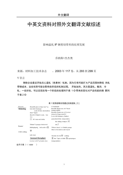
一些好处,可以实现在每一个阶段的处理列于表 1 O 带来的变化对产品性能的摘 要列于表2 O表1优势能够实现通过实施温轧 [1 ]Benefit [jess ewigy usa^e :lesi slab damagescale I CKK ; incieaiied,tlnw^hputRe L I UGV limit wcaf : leuwa- Cwmfnmti Resulls fiiom use of i^heat temperaliHe Results Emm use of Lower ichcal tcTnpcratuTC Lcsx ioll dmngcs, bighcr口 DU run-out tablaThinn^l gauges bicirswd thifughpul ; ieii acid u 詛举 Lower roUi^g leads; less panoductivily e&pecialLy fbr tiling tviiipvr 对 un;》Where heat \OHR limils gaugeDm to th uuici-scale tayuiMostly for hi 妙 coilnig icmpemiuics全尺寸表(< 1000 )Pickliti^ C D H rolling 里fbr ”igh ccUifiE 伽ipeiatupes Ptocess ioll wtai表2改进产品性能归因于温轧[1 ]P WH I UCI BencfilA J wBini-uplkd pivducls S P C ICI (LC a)Only for lugji cdlbig teniper^TutcsHigb&i r value (1^)Only if using lubiication and low coiling fempemtures followed byannealingNcn-a洋ing Only for low reheat tenipeiann'es and high coiling temperatures(LC) nr low coiling 杞nipeiatares fblkywed by annealingCcld-ipll&d products Softer (LC)Only for high coiling lemperatuiEsHigher *'• value pF)Quly if iiSiin勒lubiication iii warm rollinig and low tempei p-K I UTCS E^ILcwed by aniiealixi^全尺寸表(< 1000 )其他的好处在表1是相当明显的,硬度的影响因素,R值和老化性能概述在表2倒没有这么明显。
热轧工艺外文文献翻译、中英文翻译、外文翻译
附件1热轧工艺该轧机的主要功能是将半成品钢重新加热到接近其熔点,然后通过由共计7.7万的大功率连续滚动驱动马力发动机带动的12道连续轧制使钢板变得更薄更长,最后卷曲被拉长的钢板以运输到下一道工序。
热轧板卷的重量高达30吨至30”和74”。
将8至9英寸厚、36英尺长的钢板被卷成薄如16英寸和1 / 2英里长的带钢。
线圈由两个内径('眼睛')为30”卷取机,外径上限分别为72”和74”分别与850和1000磅每英寸宽(PIW)相对应的两个卷曲机产生。
该厂为每一个CSI提供售后业务,以及负责运输成品给CSI顾客。
大部分材料是由一种自动线圈处理系统运出轧机,通过运输线被分批运往轧机的东侧,直到它被冷却到足以载入铁路车辆。
加热炉对于热轧工艺至关重要的是它的步进梁加热炉,国家的最先进的设备,现在优于三老一辈(推车)式炉。
额定生产速度为每小时270吨,效率和与板温一致的方面得到改善以使生产率能比计划提高25﹪。
把这些钢从室温加热到2200~2400摄氏度需每天消耗约10立方米的天然气。
就像板材是按订单分配,日程安排是规定的,材料被热轧厂最西端的板厂的铁路小车和起重机分批运输。
在一条轧制线上,每一放一个轧板。
因为轧板被放置在南侧加热炉的控制门的前边,所以其规模和重量是确定的。
当炉内的空间足够,大型电镀机械推拉臂能够将板材移到炉内。
一旦进入内部,板材由大约8英尺长的炉板支撑,它是通过冷却水的耐火涂层管也被称为滑轨。
为了降低钢板残留的冰点(滑板标记),滑板间距变化大约为熔炉内部空间的三分之二。
两个独立的滑轨装置,一个固定,一个运动,轮流支撑钢板当它在炉内运动时经过一个由一对大型液压缸提供能量的机架。
该炉内部的宽是38'9”,从地面到天花板有15英尺,142’长。
它分为管制区内的温度:预热,顶面和底,加热,顶部和底,浸泡,顶和底,东和西。
预热和加热区燃烧一种天然气的混合物,同时通过在熔炉侧边的大量燃烧器预燃空气,加热钢板的上部和底部到接近其排气温度。
不锈钢钢材机械外文文献翻译、中英文翻译、外文翻译

外文原文:Stainless SteelPetro-chemical industry with its own production of some of the features, such as its operating temperature range, low-temperature conditions up to -196 ℃, temperatures can reach more than 500 ℃; operating pressure there is external pressure, vacuum, atmospheric pressure, medium pressure, high pressure, ultra-high pressure (more than 100MPa); In addition, the operating environment in the medium complexity, such as the existence of corrosion, wear and tear, and flammable, explosive, toxic and other solid, gaseous, liquid and a variety of mixed media chloride, sulfide and other salt category. Therefore, the petrochemical industry in the use of stainless steel, the requirements of stainless steel has strong corrosion resistance, including anti-chloride, sulfide and other corrosive salts; resistant to high temperature and low temperature performance. Among them, the petrochemical plant at 500 ~ 600 ℃, the equipment and pipe materials in general to choose a variety of austenitic stainless steel-based, such as 304H, 316,321, such as austenitic stainless steel has been widely used; and for oil exploration, the development of the field of stainless steel with anti-called carbon dioxide, hydrogen sulfide corrosion properties. At present, China's crude oil exploration, development is mainly used in 3Cr, 9Cr, 13Cr, super 13Cr and containing more than Cr22 stainless steel thick-walled, non-magnetic drill collar and drill pipe.At present, China's petrochemical industry in the stainless steel variety of choice, in general to 304 mainly, steel plate thickness of 6 to 22 millimeters, the main polymer used in the construction of storage tanks, heat exchanger shell. In addition, some pieces of the use of reactor tower 316L, TP347, etc., the thickness of 2 ~ 6 mm. Glacial acetic acid and liquid delivery vehicles (train tanker) General use of 304 and 306 plate. In addition, production of the device because of the existence of urea carbamate amine condensate, a highly corrosive, generally stripper, separation, and the use of 316L stainless steel condenser. On the stainless steel clad plate, such plate mainly used in oil refining equipment reaction tower, commonly used for 20R +0 Cr13AL, 16MnR +0 Cr13AL, 20R +0 Cr13 such. Due to the substrate, rehabilitation materials and productionmethods, equipment limitations, domestic composite steel plate thickness, length far from being able to fully meet the demands of the petrochemical industry. In addition, the domestic stainless steel plate splicing, heat treatment, testing and other means yet to be improved.As a result of a wide range of stainless steel, petrochemical industry, currently used for the type of austenitic stainless steel, of which 304 brands of stainless steel plate, tube forgings largest amount, 316,304 L, 316L of the plate, tube, forging a larger amount, ASTM standard TP321, TP347, TP316 brands of boiler tubes, heat exchanger is also gradually increasing dosage. In addition, a special two-way stainless steel as a result of corrosion resistance, Chiang Kai-shek in the petrochemical industry has been rapid promotion and use, of which two-way gradually increasing the amount of stainless steel tubes. At present, China's petrochemical industry in the use of stainless steel is about 70,000 tons, of which stainless steel plate (8 mm or more) the amount of approximately 10,000 tons, stainless steel composite plate is about 15,000 tons, stainless steel seamless steel tube is about 40,000 tons , stainless steel pipe is about5000 tons.Domestic stainless steel in the petrochemical field of application of thereasons for not widespreadAt present, the domestic stainless steel in the petrochemical field of application is not extensive, mainly in the following reasons: First, do not support the issue of standards. China's petrochemical industry has been formed to meet the development needs of the standard system; at home and abroad for high-pressure, high-sulfur, carbon dioxide high "three high" natural gas production equipment, material smelting, manufacturing, testing, testing technology subsidiary norms and standards is still incomplete. Second, product problems. In this regard, mainly stainless steel plate, tube, forging, welding material is not matching. Third, the issue size. Domestic metallurgical industry needs of the petrochemical industry in the thick wide board, large-diameter, thick-walled steel pipe production capacity is very limited. Fourth, quality issues, product qualitystainless steel tube instability. Fifth, research and development problems. New varieties of the domestic stainless steel R & D and production is still unable to meet the petrochemical industry's development needs. Inaddition, the stainless steel research, production and exchange of information between users of the existence of the problem poor. As a result of these factors, the need for stainless steel and petrochemical industries there are many varieties of domestic enterprises can not provide, such as four meters wide of the heavy plate production in China is not yet, there are many forms of stainless steel equipment is imported. In addition, domestic enterprises in product development with foreign enterprises is still lagging behind compared to, for example, some steel companies in Europe every year to launch a dozen new varieties of stainless steel, and Chinese enterprises in this respect, the work is notenough.The five major trends in the petrochemical proposed new requirementsfor stainless steelThe future of China's petrochemical industry will move towards the top five trends in the development of stainless steel products and higherrequirements. First of all, the future of China's oil and gas field exploration and development efforts will further increase. Such as carbon dioxide will be injected back underground ways to reduce carbon dioxide emissions and improve the oil recovery rate. At the same time, China's natural gas exploration and development efforts will be greater than the crude oil exploration and development, and to the high sulfur content, carbon dioxide area development (16% hydrogen sulfide content, carbon dioxide content of about 8%), and will further deepen the depth of wells, land Sham Tseng will exceed the 8000 meters. Second, the petrochemical plant will be large scale. Ethylene production of single device will exceed one million tons; refining single factory refining capacity more than 15 million tons; of purified terephthalic acid (PTA) production capacity of a single plant more than 800,000 tons; stainless steel tanks to the large-scale development. The third is run petrochemical plant will be a long-term development, and gradually overhaul the current cycle of thetransition to 3 years. Fourth, the petrochemical production will diversify the source of materials development. With the improvement of the requirements of environmental protection and energy consumption structure, using natural gas as raw materials of chemical industry is developing rapidly. As a result of natural gas at minus 160 ℃ can be achieved under the conditions of liquefaction, so the need for stainless steel storage and transportation equipment. In addition, as China's LNG imports increase in coastal areas need to receive large-scale construction, working capital and storage facilities, can be expected in this regard will be very large stainless steel consumption.These petrochemical industry development trend of stainless steel products, specifications and varieties have put forward new demands. From anti-corrosion requirements, the petrochemical industry production device temperature, pressure, media are major changes have taken place, stainless steel used in a more harsh environment, anti-corrosion performance by a single change to the composite performance. In the processing performance, the requirements of stainless steel a higher intensity, better toughness, weldability and good processability. In geometry, the requirements of stainless steel products and high precision, width increased, large-diameter steel pipe, steel pipe wall thickness increased. In the standards, stainless steel production as soon as possible with international standards. In addition, the petrochemical industry as a result of each of wells, each set of conditions of service refining device there is a difference, related stainless steel production enterprises should be based on the actual situation in the provision of personalized services. In addition, with the increased usage of stainless steel, stainless steel used in economics is even more important. Therefore, the domestic iron and steel enterprises, especially the steel pipe industry should improve the technological content of products and value-added, high-end product market occupation. At present, many European steel is no longer the production of low value-added oil well pipes, and will focus entirely on high added-tube, the preparation for these high-end products occupied theChinese market. (FocusRecently, China Special Steel Enterprises stainless steel branch of Li Cheng, executive president of the stainless steel industry in talking about China's problems in the development pointed out that the stainless steel to replace imports from the side, although capacity has been able to achieve self-sufficiency, but in fact only part of to replace imports, it is necessary to fully or largely replaced by imports, but also depends on our variety and quality products can meet the various requirements. He also pointed out that the market of fake and shoddy products that seriously endangers the users of stainless steel, it is proposed to increase the relevantdepartments the crackdown.Said Li Cheng, China's stainless steel production capacity from the already self-sufficiency can be achieved, but only a partial substitute for imports. Common market of the four most common grades, namely, 316 and 304 Austenitic. Ferrite 409 and 430, including 304 in the world, accounting for 50 percent of consumption, the use of nearly a hundred years of history. But it is not a single species to the new production of the 304 as an example, in order to meet the varying demands of customers, they will have a brand dozens of varieties, the same as a result of the 304 different varieties in the market price per ton can also be a difference of several hundred dollars to a thousand dollars, we can see the value of a good product, there are markets. This value needs to be done can be. 430 the past two years has developed very rapidly, in fact, this is an in production is not easy to master the varieties, r value of the performance of stamping a crease resistance, it is difficult to achieve, and now the world's more advanced r ≥ 1.2, At a time when there was virtually no punching fold, China and some production plants in both there are still some problems; 409 brands, it seems easier to see the production of components, but it's forming, and welding of the automobile industry to meet the requirements of the development will not be easy.In recent years, the development of China's manufacturing of stainless steel materials for many new requirements, such as power generation, petrochemical, and automobile industries are faced with the newrequirements of the material. Power generation systems need a lot of supercritical required stainless steel pipe, China is now still can not produce, the number of heat exchanger tubes we find it difficult to adapt, petrochemical development needs of some special stainless steel We are also in the trial. Automobile manufacturing, a number of special varieties of high-quality stainless steel requirements, we simply have not yet produced. To meet the needs of users and the use of the industry is necessary to combine joint research, innovation through research in order to solve the problem. In short, we can not just the manufacturingenterprises in the advanced hardware, we are in process technology, smelting technology and the development of both species have a larger gap, attracted the greatest attention to and constantly strive to improve.China's stainless steel market is facing a prominent issue is that the market is flooded with fake and shoddy products. In this regard, Li Cheng pointed out that in recent years because of soaring nickel prices do not appear in accordance with international and domestic standards of the low production of low nickel chromium high manganese so-called "200"series of steel, poor corrosion resistance, in which steel Based on the more serious occurred, the evolution of the market is now known as the "double-free steel" of inferior goods. The so-called double-free is no nickel, non-magnetic, this so-called "double-free" Steel does not have the non-rust and corrosion-resistant properties, which cause great harm to the user at the same time, for the jerry-built illegal producers and sellers the opportunity to bring huge profits, a very serious problem. Another is the emergence of stainless steel decorative tube size and thickness specifications for the production of non-serious "shrink", does not have the necessary stiffness of stainless steel tubes, so all kinds of deception users, to the credibility of stainless steel brought the crisis.At present the country is building a number of major projects, such as the Beijing Olympics and Shanghai World Expo project works, if only to keep the prices down in the tender, it will naturally arise in a cheap fake and shoddy products. Therefore, he called on the community especially the construction of the developers, must be quality-oriented, to avoid allkinds of hidden dangers and accidents to avoid failure and lead to very serious consequences as a result of the material. We should be treated in good faith users of harm to reputation and the interests of consumers of stainless steel act. Suggested that the state departments intensify thecrackdown.Development history::The invention of stainless steel is the world's metallurgical history of a significant achievement. The early 20th century, khazrajiya (LBGuillet) in 1904 -1906 and Porter million (AMPortevin) in 1909-1911 in France; Giessen (W. Giesen) in the years 1907-1909, respectively, in the United Kingdom found Fe - Cr and Fe-Cr-Ni alloy resistance to corrosion.蒙纳尔茨(P. Monnartz) in 1908-1911 in Germany put forward a theory of stainless steel and passivation of the many viewpoints.The inventor of stainless steel for industrial use are: Brearley (H. Brearly) 1912-1913 was developed in the United Kingdom with Cr12% -13% of the martensitic stainless steel; Dan Qi Zeng (C. Dantsizen) 1911-1914 in The United States has developed with Cr14% -16%, C0.07% -0.15% of ferritic stainless steel; Maurer (E. Maurer) and Strauss (B. Strauss) 1912-1914 was developed in Germany with C <1%, Cr15% -40%, Ni <20% of austenitic stainless steel. In 1929, Strauss (B. Strauss) made of low carbon 18-8 (Cr-18%, Ni-8%) stainless steel patent.In order to solve 18-8 steel sensitized state Intergranular corrosion, in1931 Germany's Huo译文:不锈钢石油化工行业生产具有自身的一些特点,例如其操作温度范围宽,低温条件时可达-196℃,高温时可达500℃以上;操作压力有外压、真空、常压、中压、高压、超高压(大于100MPa);此外,操作环境中介质复杂,如存在腐蚀性、磨损性、易燃、易爆、有毒等固态、气态、液态以及各种混合介质氯化物、硫化物和其他盐类。
机床的论文中英文资料外文翻译文献
机床的论文中英文资料外文翻译文献引言机床是制造业中重要的设备,用于加工各种零部件和制造产品。
本文汇总了关于机床的论文中英文资料的外文翻译文献,以供参考和研究使用。
外文翻译文献列表Author: John Smith John SmithYear: 2015 20152. Title: Advanced Techniques for Machine Tool Analysis Title: Advanced Techniques for Machine Tool AnalysisAuthor: Jennifer Lee Jennifer LeeYear: 2016 20163. Title: Intelligent Control Systems for Precision Machining Title: Intelligent Control Systems for Precision MachiningAuthor: David Wang David WangYear: 2018 2018Abstract: This paper focuses on intelligent control systems for precision machining. It discusses the integration of artificial intelligence and control algorithms to enhance the precision and performance of machine tools. The paper presents case studies on the application of intelligent control systems in precision machining processes. This paper focuses on intelligent control systems for precision machining. It discusses the integration of artificial intelligence and control algorithms to enhance the precision and performance of machine tools. The paper presents case studies on the application of intelligent control systems in precision machining processes.4. Title: Advances in Machining Processes for Hard-to-Machine Materials Title: Advances in Machining Processes for Hard-to-Machine MaterialsAuthor: Emily Chen Emily ChenYear: 2019 2019Abstract: This paper reviews recent advances in machining processes for hard-to-machine materials. It discusses the challenges associated with machining materials such as titanium, nickel-basedalloys, and ceramics. The paper highlights the development of new cutting tools, machining strategies, and technologies to improve the machinability of these materials. This paper reviews recent advances in machining processes for hard-to-machine materials. It discusses the challenges associated with machining materials such as titanium, nickel-based alloys, and ceramics. The paper highlights the development of new cutting tools, machining strategies, and technologies to improve the machinability of these materials.5. Title: Optimization of Machining Parameters for Energy Efficiency Title: Optimization of Machining Parameters for Energy EfficiencyAuthor: Michael Liu Michael LiuYear: 2020 2020Abstract: This paper explores the optimization of machining parameters for energy efficiency. It discusses the impact of machining parameters, such as cutting speed, feed rate, and depth of cut, on energy consumption in machining processes. The paper presents optimization techniques and case studies on reducing energy consumption in machining operations. This paper explores theoptimization of machining parameters for energy efficiency. It discusses the impact of machining parameters, such as cutting speed, feed rate, and depth of cut, on energy consumption in machining processes. The paper presents optimization techniques and case studies on reducing energy consumption in machining operations.结论以上是关于机床的论文中英文资料的外文翻译文献,希望对研究和了解机床技术的人员有所帮助。
H型钢制作工艺外文文献翻译、中英文翻译

外文资料H-beam production processWith the development of industrialization and the arrival of information age, more and more advanced equipment for production of the liberation of a large number of labor, create more social value, increase the production safety coefficient at the same time. In terms of welding h-beam production, h-beam group to the emergence of machine and the use of gantry submerged arc welding welding technology has brought significant technological innovation.Since h-beam automatic group on the machine put into use, due to the decisive role of h-beam technical parameters to ensure become indispensable in the group of process equipment. H-beam automatically set to the preferred cutter blanking machine work, after flat steel (including flange plate and web plate) in the group of orbit of the machine, with a group of machine clamping device for wing plate and web plate initial clamping positioning, the active entry table input artifacts to host, host prior to adjust benchmark web and flange size, namely artifacts can be accurate positioning spot welding, automatic cycle button, then the head location and spot welding, and then use some good h-beam gantry crane hanging from the group, after the machine into the next procedure. H-beam set of machine is one of the important equipment, ensure the h-beam technical parameters is mainly composed of four large transmission mechanism, specific include: web roller drive mechanism, wing on the two positioning clamping mechanism, about web positioning clamping mechanism and input/output roller transmission mechanism, etc. Pressure on web wheel transmission mechanism adopts hydraulic clamping, use by hydraulic cylinder transfer of power is the highest roller, roller center external use V groove design, to ensure that regulations within the scope of different width of accurate positioning and automatic web for accurate, do not need to reset every time; On roller thrust bearing on inside, can not only convenient for h-beam transmission on the roller table, still can make the h-beam web can fully contact with wing during transmission, for guarantee of h-beam section height size, played an important role.Through a large number of instances prove that operation, including automatic h-beam group on the machine and gantry submerged arc welding, a large number of the application of advanced instruments and equipment, saving the cost and reduce the time limit for a project, to ensure the quality of reliable, ensure no potential safety hazard and so on. Steel alloy steel, high-quality steel bar mill rebuilding project of 3000 t welded h-beam applied the new equipment, h-beam welding qualified rate reached 99%, greatly improved the production quality and reliability, and productivity increased five times, and the whole project of the welding process in the traditional group saves about $200000, created a considerable economic benefits.In welding h-beam production, h-beam group to the emergence of machine and the use of gantry submerged arc welding welding technology has brought the significant technical innovation, respectively, analyzing their working principle are introduced, and the group in the welded h-beam production and welding process improvement techniques, through a largenumber of instances prove that operation, including automatic h-beam group on the machine and gantry submerged arc welding, a large number of the application of advanced instruments and equipment, saving the cost and reduce the time limit for a project, to ensure the reliability of the quality, ensure no safe hidden trouble, etc., can be used effectively provide a reference for similar projects.中文译文H型钢制作工艺随着工业化的发展和信息化时代的到来,越来越先进的生产设备解放了大量的劳动力,创造了更多的社会价值,同时增加了生产安全系数。
外文翻译--现代化矫直轧制薄品设备的自动化控制
外文翻译原文:AUTOMATING THE CONTROL OF MODERN EQUIPMENT FOR STRAIGHTENING FLAT-ROLLED PRODUCTS The company Severstal’ completed the successful introduction of new in-line plate-straightening machines (PSMs) on its 2800 and 5000 mills in August 2003 [1, 2, 3]. The main design features of the machines are as follows:●each machine is equipped with hydraulic hold-down mechanisms (toimprove the dynamics and accuracy of the machine adjustments and more reliably maintain a constant gap);●the machines have mechanisms to individually adjust each work roller with the aid ofhydraulic cylinders (this broadens the range of straightening regimes that can be realized by providing a measure of control over the change in the curvature of the plate);●each work roller is provided with its own adjustable drive (to eliminate rigidkinematic constraints between the spindles);●the system of rollers of the PSM is enclosed in cassettes (to facilitate repairs andreduce roller replacement costs);●the PSM has a system that can be used to adjust the machine from a nine-rollerstraightening scheme to a five-●roller scheme in which the distance between the rollers is doubled (this is done towiden the range of plate thick-nesses that the machine can accomodate).Thus, the new straightening machine is a sophisticated multi-function system of mechanisms that includes a wide range of hydraulically and electrically driven components controlled by digital and analog signals. The entire complex of PSM mechanisms can be divided into two functional groups: the main group, which includes the mechanisms that partici-pate directly in the straightening operation (the hold-down mechanisms, the mechanisms that individually adjust the rollers,the mechanisms that adjust the components for different straightening regimes, the mechanism that moves the top roller of the feeder, and the main drive); the auxiliary group (which includes the cassette replacement mechanism, the spindle-lock-ing mechanism, and the equipment that cools the system of rollers). Althoughthe PSM has a large number of mechanisms,the use of modern hydraulic and electric drives has made it possible to almost completely automate the main and auxiliary operations performed on the PSM and the units that operate with it.Described below are the features and the automatic control systems for the most important mechanisms of the plate-straightening machine.The operating regimes of those mechanisms are also discussed.The hydraulic hold-down mechanisms (HHMs) of the sheet-straightening machine function in two main regimes:the adjustment regime;the regime in which the specified positions are maintained.There are certain requirements for the control system and certain efficiency criteria for each regime.In the adjustment regime, the control system for the hydraulic hold-down mechanisms must do the following:●synchronize the movements of the hydraulic cylinders and keep the angulardeeflection within prescribed limits;●maximize speed in adjusting the machine for a new plate size;●maintain a high degree of accuracy in positioning the mechanisms;Fig. 1. Block diagram of the control system of the hydraulic cylinder.The control system has the following requirements when operating in the maintenance regime:●stabilize the coordinates of the top cassette and the top roller of the feeder with a highdegree of accuracy;●minimize the time needed to return the equipment to the prescribed coordinates whendeviations occur (such as due to the force exerted by a plate being straightened).Need for synchronization. Experience in operating the plate-straightening machine in plate shop No. 3 at Severstal’ has shown that the most problematic factor in adjusting the machine is the nonuniformity of the forces applied to the hydraulic cylinders. This nonuniformity is due to the asymmetric distribution of the masses of the moving parts of the PSM (in particular, the effect of the weight of the spindle assembly). Displacement of the “hydraulic zero point” relative to the “electrical zero point” in the servo valves is also a contributing factor.The latterreason is more significant, the smaller the volume of the hydraulic cylinder.Thus, the HHM of the top roller of the feeder is the most sensitive to drift of the zero point.There are also other factors that affect the dynamism,simultaneousness,and synchronism of the operation of the hold-down mechanisms:●differentiation of the frictional forces on parts of the hydraulic cylinders due todifferent combinations of deviations in the dimensions of the mated parts, despite the narrow tolerances;●differences in the “springing” characteristics and the indices characterizing the inertiaof the hydraulic supply channels (due to differences in the lengths of the pipes leading from the servo valves to the hydraulic cylinders).Thus, since the PSM is not equipped with devices to mechanically synchronize the operation of the cylinders, the ransmission of signals of the same amplitude to the inputs of the servo valves inevitably results in a speed difference that can seriously damage the mechanisms.To minimize and eliminate the effects of the above-mentioned factors, we developed an algorithm for electrical synchronization of the hold-down mechanisms.The HHM of the top cassette, composed of four hold-down cylinders and four balancing cylinders, is designed to ensuremobile adjustment of the machine to set the required size of straightening gap (in accordance with the thickness of the plate) andmaintain that gap with a specified accuracy in the presence .and absence of a load on the housings from the straightening force.The hydraulic system of the hold-down mechanism is designed in such a way that only one chamber of the hydraulic cylinders is used as the working chamber.The second chamber is always connected to the discharge channel.The top cassette is lowered when the balancing forces are overcome by the hold-down cylinders.The cassette is raised only by the action of the balancing cylinders.This arrangement has made it possible to eliminate gaps in the positioning of the equipment.The HHM of the top roller of the feeder consists of two hydraulic cylinders. Hydraulic fluid is fed into the plunger chamber when the roller is to be lowered and is fed into the rod chamber when it is to be raised.Control Principles. Individual circuits have been provided (Fig.1) to control the hydraulic cylinders of the hold-down mechanisms.The control signal (Xctl) sent to the input of the servo valve is formed by a proportional-integral (PI) controller (to improve the sensitivity ofthe system, we chose to use valves with “zero” overlap).The signal sent to the input of the controller (the error signal Xerr) is formed as the difference between the control-point signal for position (Xcpt) and the feedback signal (Xf.b).The latter signal is received from the linear displacement gage (G) of the given hydraulic cylinder.The gages of the HHM for the top cassette are built into the balancing hydraulic cylinders (HCs).The cylinders are installed in such a way that their movements can be considered to be equal to the displacements of the corresponding cylinder rods, with allowance for certain coefficients.The gages in the HHM for the top roller of the feeder are incorporated directly into the hold-down cylinders.The integral part of the controller is activated only during the final adjustment stage and during stabilization of the prescribed coordinate.When the displacements exceed a certain threshold value, the functions of the PI controller are taken over by a proportional (P) controller with the transfer function W(s) = k.Thus, Xctl(t) = kXerr(t).When there are significant differences between the displacements of the working rollers,the difference (error)between the control point and the feedback signal from the linear displacement gage reaches values great enough so that the output signal which controls the operation of the servo valve reaches the saturation zone.In this case, further regulation of the displacement rate and,thus synchronization of the movements of the cylinders becomes impossible as long as the error exceeds the value at which Xctl is greater than the boundary value for the saturation zone (Xsat).The limiting error–the largest error for which Xctldoes not reach saturation–is inversely proportional to the gain of the controller k: Xerr< Xsat/ k. Solving the given problem by decreasing k leads to a loss of speed in the adjustment of the PSM and a decrease in control accuracy during the straightening operation.Thus, to keep the control signal from reaching the saturation zone when there are substantial displacements, the system was designed so that the input of the controller is fed not the actual required value (Xrq) but an increment (∆X) of a magnitude such that the condition k∆X < Xsat is satisfied.The control point is increased by the amount ∆X after the position of the cylinder has been changed by the amount corresponding to the increment having the largest lag relative to the cylinder’s direction of motion. The adju stment of the control point is continued until the difference between the required value and the actual position of the mechanism becomes less than the increment:Xrq –Xf.b < ∆X.Then the input of the controller is fed the value Xcpt, which is equal to the required adjustment: Xcpt= Xrq.The adjustment is thus completed.Use of the principle of a stepped increase in the control point makes it possible synchronizethe movements of the cylinders and set the control point with a high degree of accuracy for almost any ideal repetition factor.Mechanisms for Individual Adjustment of the Working Rollers.The plate-straightening machine is designed so that each working roller can be moved vertically, which is done by means of a hydraulic cylinder acting in concert with a V-belt drive.The cylinders are supplied with power from servo valves operated with proportional control.A linear displacement gage is built into each cylinder to obtain a feedback signal on the position of the roller.Since these gages are actually transmitinginformation on the position of the cylinder rods rather than the working rollers themselves, the following conversion is performed to obtain the rollers’ coordinates:Xrol= kredXf.b,where kred is the gear ratio of the drive;Xf.b is the position of the cylinder rod measured by the linear displacement transducers.Thus, a position feedback circuit is provided to control the position of each working roller. Figure 1 presents a diagram of one of the circuits.The control signals are generated by means of the PI controllere, which has made it possible to achieve a high degree of accuracy in adjusting the system without sacrificing speed.The individual drive of the rollers. The above-described design is based on the use of individual ac drives with motors of different powers fed from frequency converters. Each individual drive offers the following advantages over a group drive:●greater reliability thanks to the absence of additional loads on the components of themechanisms due to differences between the linear velocities of the working rollers and the speed of the plate;●the possibility that the machine could continue to operate if one or even severaldrives malfunction;in this case,the corresponding rollers would be removed from the straightening zone;●the possibility that the linear velocities of the rollers could be individually correctedin accordance with the actual speed of the plate;such a correction could be made either asa preliminary measure (on the basis of measured and calculated values) or during thestraightening operation (on the basis of the data obtained from the frequency converters, which employ artificial intelligence).The main drive of the straightening machine rotates nine straightening rollers and two housing rollers.This drive must be highly reliable in operation, since the fact that the PSM isinstalled in the mill line means that sizable production losses can be incurred if the drive fails to work properly even for a short period of time.The requirements that must be satisfied by the drive are determined by the operational and design features of the machine as a whole:●the plate being straightened must create a rigid kinematic coupling between thestraightening rollers, the rollers of the housing, and the adjacent sections of the roller conveyors;●the plate should undergo elongation during the straightening operation as a result ofplastic deformation, with the increments in length being different on each working roller due to the differentiation of the bending radii;this situation leads to a nonuniform increase in the speed of the plate as it moves toward the end of the PSM;●it must be possible to use working rollers of different diameters (this being done, forexample, due to nonuniform wear or regrinding);●the loads on the rollers should be differentiated in accordance with the chosenstraightening regime;●reverse straightening should be possible.In light of the above factors and the actual operating regimes of the plate-straightening machine being discussed here, the following requirements can be established for the electric drive:●regulation of speed within broad limits, including startup of the motors underload;●operation in the reverse regime;● a rigid characteristic ω = ƒ(M);●high degree of accuracy in maintaining the prescribed speed;●fully synchronous operation.The element base. The drive of the rollers was built with the use of asynchronous three-phase motors having a short-circuit rotor.The motors were designed by the German company VEM.They can continue to function under severe overloads and are reliable in operation.The motors are controlled by SIMOVERT frequency converters made by the German firm Siemens.Their modular design facilitates maintenance and repair, and the presence of a built-in microprocessor block makes it possible to execute most of the functions involved in controlling the operation of the drive (maintain the prescribed speed with a high degree of stability, recalculate the frequency of rotation in accordance with the actual diameters of therollers, diagnose the condition of the drive, control the drive’s operation, and exchange information on the PROFIBUS network).Motors of different powers are used in the system because of the differentiated distribution of the moments between the working ing different motors has made it possible to significantly reduce the cost of the electrical equipment and improve the performance characteristics of the machine as a whole.The machine has three main operating regimes: the working regime (semi-automatic and automatic), the transport regime, and the cassette replacement regime.Figure 2 shows a block diagram of the operations connected with realization of the working regime.In the semi-automatic variant of this regime, the operator controls the PSM from a control panel.In this case, the operator can do the following: choose the straightening regime from a database;correct the chosen regime;adjust the regime manually, which requires that the operator indicate the desired position of the bottom cassette (for five- or nine-roll straightening);adjust the gap between the top and bottom cassettes; set the coordinates for individual adjustment of the working rollers; choose the straightening speed and direction;generate a command to begin adjusting the machine to the specified regime.Fig. 2. Block diagram of the working regime of the PSM.The machine is adjusted to the chosen regime automatically.After the adjustment is completed, a signal is sent to the control panel indicating that the coordinates of the mechanisms have been changed and that the rollers have reached their prescribed working speeds.In the automatic variant of the working regime, the plate-straigthening machine is adjusted on the basis of data sent through a data network from a higher-level system. These data include the following information:●the thickness of the plate being straightened;●the group of steels (information on the properties of the material);●the temperature of the plate at the inlet to the PSM.The PSM is adjusted in several stages:●preliminary adjustment based on the plate thickness and steel group, for cold-rolledplates (t = 20°C);●further adjustment on the basis of data obtained from a pyrometer installed roughly 50m from the PSM;●final adjustment on the basis of data obtained from a pyrometer installed at theentrance to the machine.In the automatic variant, control over the roller conveyors adjacent to the machine is switched over to the control system of the PSM as the next plate approaches the machine.In this case, the plate cannot enter the working zone of the machine until the adjustment is completed.If it is necessary to pass a plate through the machine without straightening it, the machine is changed over to the transport regime.In this case, the top crossarm and the cassette are elevated a prescribed amount and the speed of the rollers is changed so that it is equal to the speed of the adjacent roller conveyors.The cassette replacement regime is used in the event of breakage of a roller or when it is necessary to regrind the working and backup rollers.In this case, the operator can control the operation of the auxiliary mechanisms:the spindle-locking mechanism, the roll-out cart, the mechanism that locks the bottom cassette and the cart in position, and the hydraulic cylinder that moves the cart.The mechanisms are fixed in position by means of noncontact transducers.PSM Control System. Control of the plate-straightening machine required the development of a powerful, high-capacity system that could provide the desired control accuracy in combination with rapid operation.The control system that was created is divided into two levels: the base level, and an upper level.The diagnostic system was created as a separate system.A second controller was also provided, to control the pump station of the PSM.The base level of the control system employs a SIMATIC S7 industrial programmable controller, while the upper level and the diagnostic system were built on the basis of standard computers.The computer used for the upper-level system also serves as the control panel for the PSM.Fig. 3. Network structure of the PSM control system.The different elements of the control system are linked by two loops of a PROFIBUS network (Fig.3).The first loop functions as the communications link between the controller, the upper-level computer, the diagnostics station, and the pump-station controller.The second loop links the PSM controller with the functional elements of the system (the frequency converters, linear displacement gages, and remote input/output module).The functions of the control system were divided between the base level and the upper level on the basis of the following principle: the base level was assigned all of the operations that involve receiving data from the sensors installed on the mechanisms, obtaining information from the automated process control system on the plate being straightened, and generating and transmitting control signals for the executive mechanisms (actuators); the upper level was assigned the functions of archiving the control points and monitoring the operation of the control panel.The following specific functions are performed by the base level of the automation system:●obtaining the assigned straightening parameters (roller speeds, the coordinates of thetop crossarm, and the coordinates of the rollers relative to the crossarm) from the upper-level system;●processing the parameters and sending corresponding control signals to the actuators;●obtaining information from the sensors installed on the mechanisms to determinewhether or not the PSM is properly set and ready for the straightening operation;●obtaining information from the feedback transducers installed on the mechanisms tocalculate the control actions;●analyzing the readings of the sensors to determine the accuracy of the data;TABLE 1. Specifications of the Plate-Straightening Machines●exchanging data with the pump-battery station (PBS) of the PSM and transmitting thestati on’s operating parameters to the upper-level system for display;●receiving signals from the upper-level system for manual control of the machine andthe PBS;●obtaining initial data from the upper-level system for automatic correction andtransmission of the data in order to make the appropriate adjustments.The functions of the upper-level automation system are as follows:●entering data on the straightening regimes for subsequent selection of the regime andrecording that information in a database;●manually choosing the straightening regime from the database for the correspondingplate (this is done by the operator);●automatically choosing the straightening regime from the database on the basis ofinformation obtained from the upper-level system;●manually controlling the machine in the straightening and cassette-replacementregimes;●indicating the positions of the mechanisms based on readings from the sensors and thepositions of the limit switches;●indicating the presence of a plate in the working zone of the PSM;●indicating the temperature of the plate measured by the pyrometer;●visually representing the straightening regimes and machine adjustments;●visually representing the state of the machine’s mechanisms and the PBS fordiagnostic purposes.Remote input-output module ET200 is used to supply power to the unregulated drives.Thecabinet containing the relays and contacts for these drives is located a considerable distance from the e of the module has made it possible to significantly shorten the connecting cables.Diagnostic System. The heavy concentration of electrical and hydraulic equipment included as part of the PSM–equipment which is located an appreciable distance from the machine itself and is often in hard-to-reach places–makes it more difficult to service the machine and locate the source of problems.To facilitate maintenance of the PSM and shorten repair time, it was necessary to build an advanced diagnostic system.The system is based on an industrial computer installed at the control post.It diagnoses the state of various mechanisms of the PSM, as well as its hydraulic and electrical equipment.The system can be used to evaluate the condition of the automatic switches, the temperature sensors of the motors, the linear displacement gages, terminals of the local PROFIBUS network, the currents, speeds, and direction of rotation of the motors, and other equipment and parameters.The diagnostic system can also be used to establish the operating protocol of the PSM.Its archives contains data on the time and types of errors and equipment failures that occur, the coordinates of the mechanisms, motor currents and speeds, and other information.To make the control system more reliable, the software and hardware of the diagnostics station are identical to the corresponding components of the control system’s upper level.When problems occur with the operation of the control computer, the PSM control functions can be transferred to the computer of the diagnostic system.Conclusions.The NKMZ has worked with its original partners in the Commonwealth of Independent States (CIS) to successfully introduce plate-straightening machines equipped with a modern automated control system. Use of the machines makes it possible to minimize and almost completely eliminate the dependence of the quality of the finished plates on the skill of the machine operator.The control system, together with its convenient user interface,allows even personnel with no special training to quickly master the operation of the machine.The production of high-quality products is assured as a result of the exact movements of the machine’s mechanisms and the accuracy with which their positions are maintained, which owes to the use of precision equipment with proportional control and special control algorithms.In addition, the machine is equipped with a sophisticated diagnostic system which also records its key operating parameters.The availability of the system facilitates maintenance andrepair of the machine’s many complex components.译文:现代化矫直轧制薄品设备的自动化控制谢韦尔钢铁公司在2003年8月成功完成了新引进的规格为2800—5000米尔的直线式钢板矫直机(平台相关模型)。
轧钢 外文翻译 外文文献 英文文献

附录 1 冷轧横向偏移量的控制性能摘要一些先进的轧机考虑到工作棍和支撑棍在板带所在平面内的偏移量,允许棍在三个方向变形。
这个模型用来探究冷扎横向偏移量控制系统的灵敏度对冷扎三个方向精度的影响。
它最终揭示水平工作棍偏移量的影响最大,构成了主要激励。
这种影响随偏移的程度和工作棍的直径的变化而变化,而激励的主要成分的影响尤其显著。
另外,水平轧制偏移量本身可以成为激励信号,尽管它的灵敏度大大的改变了偏移程度。
1.引言板带材冷扎机的设计需要在两个物理因素之间协调衡量:当增大轧辊直径时,总轧制力会增大;当减小轧辊直径时,变形量又会增大。
轧辊的变形使板带的材质不均匀性减小,但是使产品的外形尺寸精度和平面度得不到保证。
设计轧机时应协调这些因素,并应通过可控制的激励对因材料不均匀性引起的变形进行补偿。
一些更先进的轧机允许工作棍或支撑棍在水平面内可控制的窜动,这是靠轴承在与被轧板带平行的平面内移动实现的。
图 1 示意了这个过程。
这样的水平窜动是为了更好的保证被轧板带的平面度,但是没有专著论述这种方法,因为这方面的论文都假定所有的轧辊都在一个平面内。
但是事实上,轧机的轧辊即使没有任何的滚动偏移,也会因为摩擦力的不平衡在水平面内变形。
已经发表了的关于轧制偏斜的分析论述中最早的是 Townsend 和 Shohet,他们的模型已经大大扩展并得到了广泛印证。
他们的方法是把所有偏斜向轴向和水平方向分解,再用数学方法描述每一种变形。
Pawelski, Rasp 和 Rieckman 证实了这种模型适用于六棍轧机,而且他们和 Wang, Pan 证明了连续不确定变化拱形是怎么形成的,在这里,一对扎根反对称拱形轴向窜动可以被联系起来。
这些模型都是用简单的一维形式,建立在与轧辊和轧辊变形都垂直的方向上。
更精确一点,板带对轧辊的压力场应该是二维的,为此 Berger Pawelski 和Funke 给出了轧辊表面压扁率这样一个更精确的描述。
轧制过程中的热传递外文文献翻译、轧钢机机械外文翻译、中英文翻译
附录Heat Transfer During the Rolling Process1 WORKPIECE TEMPERATURE CHANGE IN HOT STRIP MILLAfter reheating a slab to a desired temperature, it is subjected to rolling. A rolling cycle in a typical hot strip mill includes the following main steps:1、Descaling of the slab prior to flat rolling by using high-pressure water descaling system in combination, in some cases, with edging.2、Rough rolling to a transfer bar thickness which may vary from 19 to 40 mm. The rough rolling is usually accompanied by edging and inter pass descaling.3、Transfer of the transfer bar from roughing mill to a flying shear installed ahesd of finishing mill. The shear is usually designed to cut both head and tail ends of the bar.4、Descaling of the transfer bar prior to entering the finishing mill.5、Finish rolling to a desired thickness with a possible use of interstand descaling and strip cooling.6、Air and water cooling of the rolled product on run-out table.7、Cliling of the rolled product.Various types of heat transfer from the rolled workpiece to its surrounding matter occur during the rolling cycle. Some of the lost heat is recovered by generating heat inside the workpiece during its deformation.The main components of the workpiece temperature loss and gain in hot strip mill are usually identified as follows:1、loss due to heat radiation,2、loss due to heat convection,3、loss due to water cooling,4、loss due to heat conduction to the work rolls and table rolls,5、gain due to mechanical work and friction.The analytical aspects of these components are briefly described below.2 TEMPERATURE LOSS DUE TO TADIATIONTwo methods have been employed to derive equations for temperature loss due to radiation.In the first method, the temperature gradient within the material is assumed to be negligible. The amount of heat radiated to the environment is then calculated using the Stefan-Boltzmann law:d qr =S dtTTAar)(44-ξWhererA—surface area of body subjected to radiation, m2;]d q'r—amount of heat radiated by a body,J;S—Stefan-Boltzmann constant;T—temperature of rolled material at time,K;Ta—ambient temperature,K;t—time,s;ξ—emissivity.The amount of heat lost by a body d q''ris give by:d q''r =dTcVr ρWhere c—specific heart of rolled material, J/(kg·K);Vr—volume of body subjected to radiation, m3ρ—density of rolled material, kg/m3。
- 1、下载文档前请自行甄别文档内容的完整性,平台不提供额外的编辑、内容补充、找答案等附加服务。
- 2、"仅部分预览"的文档,不可在线预览部分如存在完整性等问题,可反馈申请退款(可完整预览的文档不适用该条件!)。
- 3、如文档侵犯您的权益,请联系客服反馈,我们会尽快为您处理(人工客服工作时间:9:00-18:30)。
轧钢机论文中英文资料外文翻译文献基于振动监测的设备故障诊断技术在大型轧钢机械上的应用摘要对基于振动的设备故障诊断技术做了较全面和深入的介绍,通过实例介绍了该诊断技术在轧钢机械领域的应用。
指出该诊断技术可同时对一个测点进行复杂的时域、频域、相关域、统计域等分析,具有一定的趋势预测分析能力。
关键词轧钢机械; 振动监测; 故障诊断1前言轧钢机械属于大型的旋转机械,是轧钢厂的关键设备。
转轴组件是轧机的核心部分,它包括旋转轴、齿轮传动件、联轴器、滑动和滚动轴承等。
人们通过长期观察和实践,发现旋转机械的绝大多数前期故障都会表现出异常的振动,因此掌握机械振动的一般规律就能从振动信号中识别出常见的设备故障。
通过对振动信号波形进行简单的时域、频域以及小波分析可对振动进行一般的识别,振动的可识别性是对机械故障进行振动噪声测试分析的技术前提。
因此,采用在设备诊断技术领域较成熟的振动分析技术作为技术的突破口对轧钢机进行日常振动状态监测,就能在设备运行中或基本不拆卸全部设备的情况下,掌握轧机运行状态,判定产生故障的部位和原因,并预测未来的技术状态,从而可在早期有效地发现,以及在后期及时地抑制故障,保障生产的可持续发展。
2信号识别与获取任何机器设备在运行中都会产生振动,机器的振动信号中包含了丰富的机器运行的状态信息。
当设备发生异常或故障时,振动将会发生变化,一般表现为振幅加大。
由不同类型、性质、原因和部位产生的故障所激发的振动具有不同的特征,这些特征表现为频率成分、幅值大小、相位差别、波形形状和能量分布状况等。
振动信号的性质和特征不仅与故障有关,还与系统的固有特性有关,具体表现为同一故障发生的部位不同、故障激励传递通道(即传递函数)不同,其振动特征和响应亦会有较大的差别。
总之,设备的振动是由故障激励和系统特性所共同决定的,但很多情况下,振动特征和故障类型之间并不是一一对应的关系,不能简单地对号入座,这就给振动的识别带来一定的困难。
因此,振动的识别对于设备诊断技术的完善是至关重要的。
轧钢机械工作时轧件是非连续地被轧制的,其转速并不恒定、功率更是从空载到满负荷间周期地波动。
从原动机到轧辊间有庞大的传动和减速机构,可能出现的故障类型很多,因此检测设备、测点、点检方式和点检时间的选择对诊断的准确与否起关键作用。
为保证所测数据具有可比性,在测定数据时应遵循以下几点原则: ①每次测量要在同一测点进行,否则由于激振源到测点的传递函数不同,而使测量的结果相差很大。
②保持每次测量时机器的工况相同。
③保持测量的参数相同,一般来说,频率在10~100Hz的振动应以位移作为数采器的输出参数,频率在100~1 000Hz的振动应以速度作为数采器的输出参数,频率在1000Hz以上的振动应以加速度作为数采器的输出参数。
④使用的仪器相同和测量的方法(如传感器及其固定方式)相同。
在测振过程中,测点的选择同样影响监测结果,其选择原则是:(1) 测点应选择在振动信号传递的通道上而且路线最短的位置,尽量减少中间传递介质。
(2) 测点应选在信号反应比较敏感的部位,如轴承座、机座等。
(3) 测点应选择在便于多方位测量的位置。
一般测振动要选定三个方向(水平X、垂直Y、轴向A)来评定,特别对低频振动,更要强调其方向性(高频振动对方向不敏感) 。
(4) 对于大型机械设备,受传递函数的影响,应多点检测。
3轧钢机械等旋转机械的常见故障及其诊断方法旋转机械的常见故障,按转子类型和振动性质的不同,可分为:转子不平衡、转子不对中、基座或装配松动、转子与定子摩擦、感应电机振动、滚动轴承故障、齿轮机构的振动等。
利用振动监测技术对这些常见机械故障可进行较为准确的诊断。
3. 1转子不平衡不平衡是旋转机械中最常见的一种故障。
引起不平衡的原因较多,如安装不良造成偏心、配合松动、轴弯曲变形、加工制造误差以及长期运行中产生不均匀磨损等。
我们从离心力的计算公式易知,不平衡振动对转速的变化是最敏感的。
转子不平衡的振动特征是:刚性转子在启动时振幅随转速的增大而增大,柔性转子在启动时振幅是先增大而后减小。
在频率特征方面,不平衡振动的频率成分单一而明朗,主要表现为转子的基频;在相位方面,水平和垂直方向的振动相差90œ,且通常水平方向的振动比垂直方向的大、径向振动比轴向振动要大。
3. 2转子不对中转子不对中是指转子中心与轴承中心不对中,或多转子系统中各转子的轴线不对中,也是旋转机械的一类多发性的典型故障。
不对中有三种类型,即平行不对中、角度不对中、综合不对中。
其产生的原因有:转子及支座安装不良、轴承支座不均匀膨胀引起变形、地基变形以及热不对中等。
转子不对中的振动特征是:当转子不对中时将产生一种附加弯矩,形成附加激励,故轴向振动往往是存在不对中的一种征兆。
在振动频率特征方面,平行不对中主要激起2倍转频,角度不对中则表现为同频振动突出,它们的共同点是以旋转频率的2 倍频或4 倍频为主,尚伴有高次倍频。
在相位特征方面,平行不对中时,转子两端径向振动相位相差180œ;角度不对中时,联轴器两端轴向振动相位相差180œ,而径向相位相同。
3. 3基座或装配松动松动常和不平衡相伴生,表现为非线形的振动特征。
地脚松动引起的振动方向特征很明显,表现在垂直方向的振动很强烈。
由零件配合松动引起的振动,其方向特征不明显。
在振幅方面,松动引起的振动随负荷的增加而增大,但对转速表现出无规律的变化,忽大忽小,呈跳跃式变化。
在振动频率特征方面,除基频成分外,基频的奇数倍频突出(常高于基频的幅值) ,伴有3倍、5倍、7倍及0. 3~0. 5倍的谐波成分,频谱结构成梳状。
3. 4转子与定子摩擦此类摩擦属干摩擦,大多表现为径向摩擦。
摩擦振动属于非线性振动,频带范围很宽,除基频外,还有2倍、3倍以及1 /3、1 /2 等谐波成分。
在时域波形上,常表现为削波状态,“截头余弦”形状的波形是摩擦故障特有的重要标志。
在某些特殊情况下,摩擦还可能激起系统的固有频率振动。
3. 5感应电机振动故障特征电动机是一种典型的旋转机械,在机械故障的表现方面具有旋转机械的共同特点,如存在转子不平衡、不对中、松动、摩擦等故障类型。
感应电机的振动故障的一大特点是包括机械和电气两方面内容,发生的故障除机械因素外还与电气相关,如转子与定子间磁隙不均匀、电压不稳定、匝间短路等也会引起电机的异常振动。
当电动机在运行中突然给它断电,其时如果振动立即下降为零,即说明电动机存在电气方面的故障,否则,属于机械故障。
3. 6 滚动轴承故障滚动轴承是旋转机械转子系统的重要支撑部件,其基本结构包括外圈、内圈、滚动体、保持架等元件。
对滚动轴承实施振动诊断的基本方法是频率分析,因为滚动轴承每一个元件都有其各自的故障特征频率。
理论上,通过频率分析不但能判断轴承有无故障,而且可以具体判断轴承中损坏的元件。
滚动轴承的故障特征频率(简化计算)为:内圈通过频率F = 0. 6Z •Fr,外圈通过频率F = 0. 4Z •Fr,保持架通过频率F = 0. 4Fr,其中Z 为滚动体个数, Fr 为轴承内圈回转频率。
还需指出的是滚动轴承的振动与安装也有关,如安装滚动轴承的旋转轴系弯曲、轴承装歪、轴承紧固过松或过紧都会引起振动,其振动频率成分也含有滚动体通过频率和高次谐波。
3. 7 齿轮机构的振动特征及诊断齿轮是旋转机械的重要部件,其运行状态的好坏直接影响到整个机组的正常工作。
在齿轮箱中的各类零件中,失效比例分别为齿轮60%、轴承19%、轴10%、箱体7%、紧固件3%、油封1% ,可见在所有零件中齿轮自身的失效比例最大。
根据国外抽样统计的结果表明,齿轮的各种损伤的概率为: 断齿41%、齿面疲劳31%、齿面磨损10%、齿面划痕10%、其它故障8%。
在理想渐开线齿形及齿轮刚度无穷大的假设下,一对齿轮在啮合运动中是不会产生振动的,但由于制造、安装及齿轮刚度不可能为无穷大等方面的问题,一对新齿轮在啮合运动中也会产生振动。
通过对齿轮运动方程的分析可知,正常齿轮传动中由于啮合刚度的周期性变化会引起参数振动;由于齿形误差的随机激励可能会引起齿轮弹性系统的共振;当齿轮出现故障时,振动往往会加剧,也会产生一些新的频率成分,这些都是齿轮的特征频率。
齿轮特征频率主要有3种,即齿轮啮合频率、齿轮自振频率和齿轮边频带。
定轴转动的啮合频率为F = Z •Fr , 行星轮系的啮合频率为F = Z( Fr ±Fc) ,其中Z 为齿轮齿数、Fr 为齿轮旋转频率、Fc 为转臂旋转频率。
直齿圆柱齿轮自振频率为F =2/)/(21m k π,其中k 为齿轮副的弹簧常数、m 为齿轮副的等效质量, 其它类型齿轮的自振频率一般由试验测定(不随转速改变而恒有的频率分量通常就是系统的固有频率, 齿轮固有频率一般为1 ~10kHz) 。
当齿轮存在故障时,由于载荷波动而产生幅值调制,由于转速波动而产生频率调制,因此在啮合频率或固有频率两旁产生等间隙( 1X)的一簇边频。
通过振动诊断判别齿轮状态,最有效可行的方法是分析齿轮振动功率谱的变化,其次是分析倒频谱(如果仪器的信噪比高, 倒频谱分析效果也很好) 。
首先看啮合频率幅值的消长;二是要看啮合频率谐波的分布;三是看边频,随着齿轮故障的发展和振动能量的增加,边频越来越丰富,幅值也增加(边频分析通常要先将谱细化) 。
4诊断实例分析对轧机进行日常振动状态检测所需的工具主要有振动传感器、数据采集器、配套软件等,目前市面上已有此类成套的设备出售。
我们选用的是北京圣迪公司的振通904型振动动平衡一体化仪器。
它的主要功能是检测振动信号并进行采集记录和预处理,通过RS232C标准串行口与微机( P486以上)通讯后可以将记录在仪器中的各种数据送入微机中,借助仪器附带的波形分析软件可对采集到的数据进行时域、频域、统计域等方面的分析,做更精细的设备故障分析和诊断,建立设备状态数据库,预报设备状态发展趋势等。
运用该仪器可以对轧机日常运行时的振动进行检测,掌握轧机的运行状态、发现和跟踪轧机的早期故障、提出维修计划、跟踪维修质量等。
以广钢连轧厂12#轧机为例,利用基于振动的设备故障诊断技术对其进行一次全面的分析诊断。
根据测点选择原则,我们选取了3个测点(图6中ZJ12 - 1、ZJ12 - 2、ZJ12 - 3) 。
2005年3月29日12#轧机被诊断为发生了齿轮断齿故障。
当天的点检现象:轧机无异响、但振值和波形有故障迹象,尤其是ZJ12 - 1测点的信号特别明显。
诊断过程用到了振值表(表1,其数值为最近6个月内的数值) 、时域波形(图1) 、自相关图形(图2) 、幅值谱图(图3) 、概率密度图(图4) 、倒频谱图(图5) 。
通过对表1、图1、图2、图3、图4、图5和图6对12#轧机进行的全面分析诊断如下:(1) 振值表:在6个月里振值表内各项指标没有明显增大现象,表明振动级数和能量在故障前后未有明显变化,小部分断齿对振值表内各项指标不敏感,这也解释了故障时设备无异响的原因。