电磁锁安装方法
电磁锁安装方法 很清楚!

电磁锁(磁力锁)的标准安装方法一.外开门的表面安装方法:(参照图一至图八)第一步:首先用螺丝刀打开盖板,再用六角扳手打边板,准备安装(见图一)第二步:拿出安装纸板,将纸板沿着虚线折叠按图二所示方法把纸板放到所需装锁的位置,然后把需要打孔的地方做上记号后打孔.第三步:A.继铁板的固定(参见图三)将内六角螺丝插入继铁板中,把橡胶华司置与两片金属华司之间,然后套在内六角螺丝上。
将继铁板插入门上打的三个孔中,同时把香菇头从门的另一面插入,利用六角扳手将继铁板锁在门上。
B.边板的固定(参见图三)把边板用两个半圆头螺丝固定在先前打孔的门框上(固定在边板的长形孔中)。
注意:不要将边板锁紧,让其能前后能移动以利于安位置的修正。
C.修正边板的位置使边板与继铁板的位置合适,目的使锁主体能与继铁板紧密的接触。
D:固定锁主体与边板锁紧边板的半圆头螺丝后,再锁上所有的沉头螺丝,然后再卸下半圆头螺丝,在适当的位置钻孔以便接线。
最后用六角扳手把锁主体锁在边板上。
(参见图四)第四步:按照说明书的指示接线。
第五步:盖上盖板,把小铝柱体塞进锁主体参见图五的螺丝孔中。
参见图六图七与图八所示为典型的外开门外置式的安装式样★安装注意事项在安装继铁板的时候,不要把它锁紧,让其能轻微摇摆以利于和锁主体自然的结合。
二、内开门的表面安装(ZL型支架的安装方法):解决外装磁力锁的内装问题。
内开门做表面安装时需要有辅助配件来协助安装,我们选用富有装饰性的优质进口铝材来制做这种安装配件:Z&L支架。
每套Z&L支架含三块铝材配件,其中较长的一块L1是配给锁主体使用;另外两块较短的Z2、Z3配给继铁板用。
Z2是安装在门上的,边上有五个沉孔,是用于固定在门上;Z3是用于固定继铁板的,边上有三个孔,中心孔应与继铁板的中心孔对齐.下面介绍安装方法。
a. 先将Z&L支架中的L1支架放在装锁的位置上,用M5*25的自攻螺丝固定于门框或墙面上。
电磁锁安装指南说明书

电磁锁安装指南说明书一、前言感谢您选择本产品,本指南将详细介绍电磁锁的安装步骤以及注意事项。
请在开始安装之前仔细阅读本说明书,并按照指引进行操作。
二、电磁锁概述电磁锁是一种常用的电动锁具,广泛应用于门禁系统中。
它由固定在门框上的锁体和安装在门上的电磁铁组成,通过电流控制锁体与电磁铁的吸合和释放。
电磁锁具有快速响应、高安全性等特点,适用于各种门控场所。
三、安装步骤以下为电磁锁的安装步骤,请按照顺序进行操作:1. 准备工作在进行电磁锁安装之前,确保以下准备工作已完成:- 确保门框和门板之间的间隙符合电磁锁的尺寸要求。
- 准备好所需的工具和安装配件,如电钻、螺丝刀、螺丝等。
- 关闭门禁系统的电源,确保操作安全。
2. 安装电磁铁a) 选择合适的位置安装电磁铁,确保其与门上的锁体相对应。
b) 使用电钻在门上钻孔,并确保孔洞深度适合安装螺丝。
c) 将电磁铁安装在门上,通过螺丝固定并紧密连接。
3. 安装锁体a) 选择合适的位置安装锁体,确保其与电磁铁相对应。
b) 使用电钻在门框上钻孔,并确保孔洞深度适合安装螺丝。
c) 将锁体安装在门框上,通过螺丝固定并紧密连接。
4. 接线连接a) 定位电磁铁和锁体上的电源接线端子,并打开接线端子盖板。
b) 根据电磁锁配套的接线图,连接电源线、开关线和地线,并确保连接牢固。
c) 关闭接线端子盖板,确保接线安全可靠。
5. 调试测试安装完成后,重新打开门禁系统的电源,并进行如下测试:a) 测试电磁锁的吸合与释放功能,确保工作稳定可靠。
b) 测试门禁系统的开关控制,确保电磁锁与系统配合良好。
四、注意事项在安装电磁锁时,需要注意以下事项:1. 安全第一在进行安装前,请确保门禁系统的电源已关闭,以免发生电击等危险。
2. 遵循规范按照本说明书提供的步骤进行安装,不得随意更改或省略任何步骤。
3. 注意电源适配根据产品规格和工作电压需求,选择适当的电源接入方式。
4. 防止潮湿环境请将电磁锁安装在防潮、干燥的环境中,避免雨水直接浸泡。
标准电磁锁-10010 20 40 60型号安装说明书

REV 1.0Fitting Instructions for Standard Electro Magnetic Lock - Model 10010/20/40/60The fixing option you use will depend on the height and depth of the Door frame header.1. Fig. 1 shows an outward opening door with a deep frame header. The Standard Flat Mounting plate which comes with the magnet can be used if measurement 'A' is at least 60mm (2.36") and 'B' is at least 80mm (3.15").2. Fig. 2 shows an outward opening door with a shallow frame header. The optional Transom 'L' bracket (AC-EMBR006) must be used if measurement 'A' is less than 45mm (1.75") and 'B' is at least 80mm (3.15").3. Fig. 3 shows an inward opening door for which the 'Z&L' bracket set must be used. The optional 'Z&L' bracket set (AC-EMBR026F) must be used if measurement 'A' is up to 20mm (0.78") and 'B' is at least 60mm (2.36"), 'C' must be at least 60mm (2.36").If any of the above measurement requirements do not match you may need to use a different magnetic lock . Important points to consider during installation:1. Check that the door is properly aligned with the door frame when in the closed position. If the gap around the door and frame is not equal the magnet should not be fitted until the door is correctly aligned.2. Always handle the equipment with care as damage to the mating surfaces of the magnet or armature plate may reduce locking efficiency.3. Ensure the correct screws and fittings from the fixing pack are used as incorrect screws or fittings will affect the operation of the magnetic lock and armature plate.4. It is essential that the magnetic lock and armature plate are correctly aligned and installed correctly.5. When using the template the door must be in the closed and latched position.6. Thread lock must be applied to all threads on the magnetic lock and fixing brackets and the armature Standard magnetic lock is suitable for Timber or Aluminium Entry and Exit doors to provide controlled access via an Access Control System. It should not be used as the only lock securing the door, a mortice deadlock or similar should also be fitted.It can also be used on an Internal door when a stronger holding force may be needed.It is essential that the Header Frame and Top Rail of the door are strong enough to accommodate the magnet and Armature Plate, if in doubt consult door and frame supplier for advice.NOTE: THIS LOCK IS SUITABLE FOR SOLID DOORS 35-53mm THICK OR HOLLOW DOORS 35-46mm THICK.A B C D E F G H I J LM N OFIXING PACK CONTENTS QTY M8 Counter sunk Allen bolt 50mm (2") long1Dome nut 41 x 12mm (1.6x0.5") ChromeAluminium spacer 43 x 16mm (1.7x0.63") (For hollow doors)No 10. 32mm (No 10x1.25") Csk wood screwNo 8. 15mm (No 8x0.6") Csk wood screw (for slotted holes)Steel washer 22mm (0.87") diameter (for Armature plate)Rubber washer 15mm (0.6") diameter (for Armature plate)*Guide pin 16 x 5mm (0.63x0.2") (split dowel)M5 x 8mm (0.31") Csk Machine screw M4 x 25mm (0.5") Csk screw (thread relieved)Allen key wrench 5 x 80mm (0.2x3.15")M8 Nylock nut (for use with 'Z' bracket)M6 Allen bolt 36mm (1.42") long Incl head**Metal spacer 21 x 9mm (0.83x0.35")**1111822222222A B C D E FG H IJLM N O * + 1 Spare(see Fig.1).2. With the door closed and latched fix the template to the door and frame. Place the edge of the template 60mm (2.4") from the side frame (see Fig.4).3. Mark the centre of each hole shown on the template and drill holes to size and depth stated on Template.4. From the outside of the door enlarge the 9mm hole to 12mm to a depth of 36mm (On Hollow doors enlarge the hole to 16mm through the outer door skin only to accomodate the a hollow door push the the Aluminium spacer (C) into the 16mm hole then cut down flush with door face. Push Dome nut (B) into Spacer (C).6. Gently tap the 2 guide pins (H) into the holes on the back of the Armature plate. Push the M8 50mm Allen bolt (A) through the countersunk hole in the Armature plate. Slide a Steel washer (F) over the M8 Allen bolt at the back of the Armature plate followed by a Rubber washer (G) and a Steel washer (F). (see Fig.5).7. Fix the Armature plate to the door using the Allen key (L) and tighten until the Armature plate sits 3-5mm away from 8. Using the Allen key wrench (L) remove the two M6 Allen bolts (N) and metal spacer (O) through the holes at the base of the magnetic lock. Slide the Mounting plate forward and lift up to remove it from the lock (see Fig.6).10mm cable hole is visible through the oval hole of the plate.Fix using two No 8 15mm Csk screws (E) through the slotted holes into pilot holes drilled previously (see Fig.7).Oplate towards the Armature plate until the edges are 2-3mm apart and parallel along the length of the armature plate (see Fig.8).O14. Hold the Magnet with the front facing the armature plate and the mushroom head screws at the top. Lift the magnet up onto the Mounting plate with the mushroom head screws located into the 13mm slotted holes and push forward towards the Armature plate. (see Fig.10).15. Fix the magnet to the mounting plate using two M6 Allen bolts (N) and Metal Spacer (O) fixed through the holes in the bottom of the magnet and tighten with the Allen key wrench (L).frame (see Fig.11) and connect to Magnet PCB as per wiring instructions on pages 7&8.17. Apply voltage to the Magnet. Close the door andcheck Armature plate is correctly aligned with the magnet. Apply firm pressure against the door to check magnet is holding properly. Remove voltage and open the door.apply Thread lock. Re-fit as per steps 6&7.19. Remove one at a time the M6 Allen bolt (N) from the bottom of the magnet and apply Thread lock. Re-fit as per step 15.20. Using the two M4 25mm Csk screw (J) fix the PCB cover plate in position on the magnet and into the counter sunk hole at the opposite end (see Fig.12). These screws will prevent the M6 Allen bolt from unscrewing (see Fig.12A).11. Mark the centres of the 6 countersunk holes through the Mounting plate.12. Drill six 3.2mm dia. holes to a depth of 25mm for the No 10. 32mm Csk screws.13. Fix the Mounting plate with the 6 No. 10 32mm Csk screws (D). (see Fig.9).ALLEN BOLTS FROM UNSCREWINGFIG 17Head Frame. (see Fig.2).2. With the door closed and latched, tape the template to the door and frame. Place the edge of the template 60mm from the side frame. (see Fig.13).3. Mark vertical lines for the 'L' bracket at the edge of the template, mark centre of each hole shown on the template. Drill all holes to the size and depth shown on template.4. From the outside of the door enlarge the 9mm hole to 12mm to a depth of 36mm (on a hollow metal door drill a 16mm hole through the outer door skin only to accommodate a hollow door push the the Aluminium spacer (C) into the 16mm hole then cut down flush with door face. Push Dome nut (B) into Spacer (C).6. Gently tap the 2 guide pins (H) into the holes on the back of the Armature plate. Push the M8 50mm Allen bolt (A)through the counter sunk hole in the Armature plate followed by one Rubber washer (G) sandwiched between 2 Steel washers (F) behind the Armature plate. (see Fig.14).7. Fix the Armature plate to the door using the Allen key (L) and tighten until the Armature plate sits 3-5mm away from the 8. Using the Allen key wrench (L) remove the two M6 Allen bolt (N) and Metal spacer (O) through the bottom of the magnetic lock. Slide the Mounting plate forward and lift up to remove it from the magnet. (see Fig.15).9. Remove the two Mushroom head screws from the top of the magnet and replace with the two M5 8mm machine screw (I).10. Use the Transom 'L' bracket (AC-EMBR006) as atemplate. Place the short side between the vertical lines on the frame (make sure it is flat against the frame) the bottom of the bracket should be 5mm below the underside of the frame header (fig 16).12. With the door closed and latched place the face of the magnet so that it touches the Armature plate and check that the hole in the top of the magnet lines up with one of the tapped holes on the bracket. If the holes do not line uploosen the M8 Allen bolt (A) making sure the gap behind the14. Pass lock cable through the cable entry hole (see Fig.19) and connect to Magnet PCB as per the wiring instructions on pages 7&8.15. Apply voltage to the Magnet. Close the door and check Armature plate is correctly aligned with the magnet. Apply firm pressure against the door to check magnet is holding properly. Remove voltage and open the door.16. Remove M8 Allen bolt (A) from Armature plate and apply Thread lock. Re-fit as per step 6&7.17. Remove one at a time the M6 Allen bolt (N) from the bottom of the magnet and apply Thread lock. Re-fit as per step 13.18. Using the two M4 25mm Csk screw (J) fix the PCB Cover plate in postion on the magnet and into the counter sunk hole at the opposite end (see Fig.20). These screws will prevent the M6 Allen bolt from unscrewing (see Fig.20A).13. Fix the magnet to the bracket using two M6 Allen bolts (N) and Metal spacer (O) fixed through the holes in thebottom of the magnet and tighten with the Allen key wrench (L). (see Fig.18).OALLEN BOLTS FROM UNSCREWINGFixing detail - Standard Double Magnetic Lock - Models 10040 and 10060REV 1.0Installation to Deep Header frame using Flat Mounting PlateInstallation to Shallow Header frame using 2 Transom 'L' BracketsThe Standard Double magnetic locks are used for a pair of double doors. They are fixed in exactly the same way as the Single version using 2 fixing packs.1. With both doors closed and latched fix the template across the centre of both doors and continue as steps 3&4 on page 2 (see Fig. 21).2. Fit the 2 Armature plates to each door as per steps 5-7 (Fig.5) on page 2.3. Remove the four M6 allen bolts (N) and Metal spacers (O) as per step 8 page 2 (see Fig.22).4. Fix the Mounting plate using 4 No.8 15mm Csk screws (E) as per step 9 page 2. Ensure Mounting plate is adjusted correctly as per step 10 (Fig.8) page 2.5. Fix the mounting plate using 12 No. 10 32mm Csk screws (D) as per steps 11-13 (Fig.9) page 3.6. Fix the Magnet to the mounting plate using four M6 Allen bolts (N) & Metal Spacers (O) as per steps 14&15 page 3.7. Fit 2 seperate cables for each magnet PCB as per steps 16&17 (Fig.11) page 3.8. Apply Thread lock to Allen Bolts as per steps 18&19 page 3.9. Fit four M4 25mm Csk screws (J) as per step 20 (Fig.12) page 3.1. With both doors closed and latched fix the template across the centre of both doors and continue as steps 3&4 on page 4 (see Fig. 23).2. Fit the 2 Armature plates to each door as per steps 5-7 (Fig.5) on page 4.3. Remove the four M6 allen bolts (N) and Metal spacers (O) as per step 8&9 page 4 (see Fig.22).4. Place the two 'L' brackets together and continue as per steps 10&11 page 4 (see Fig.24).5. Close both doors and line up Magnet with brackets as per step 12 (Fig.17) page 4.6. Fix the Magnet to the 2 'L' brackets using four M6 Allen bolts (N) & Metal Spacers (O) as per step 13 (Fig.18) page 5.7. Fit 2 seperate cables for each magnet PCB as per steps 14&15 (Fig.19) page 5.8. Apply Thread lock to Allen Bolts as per steps 16&17 page 5.9. Fit four M4 25mm Csk screws (J) as per step 18 (Fig.20) page 5.The standard magnet is designed to be operated by 12 or 24 volt DC systems. The Printed Circuit Board (PCB) in the magnet is factory set for 12V operation but can easily be changed for 24V operation (see wiring detail). The PCB also has built - in protection against Back EMF surges which means a seperate Diode or MOV is not needed. Because the magnet is Fail Unlock (Fail Safe) it needs a constant DC supply to hold the Armature plate in position, it is therefore recommended that a Rechargable Battery is fitted in the Power supply.Important Points to consider before Installation:-1. The Magnet must be connected to a Regulated DC Power supply (Ideally with BatteryBackup facility).2. Input voltage at the magnet PCB must be 12 or 24V `10%3. The PCB already has built-in protection against Back EMF surges.4. The Maximum current draw for 12V is 500mA and for 24V 250mA (Double version willdraw twice as much).5. DO NOT reverse polarity as this will result in damage to the PCB and Coil.6. There are two versions of the PCB - Unmonitored (Models 10010 and 10060) andMonitored (Models 10020 and 10040).7. Ensure all cabling and wiring connections conform to current Electrical Legislation.1. Check magnet PCB is set for correct voltage (Factory setting is 12V).2. Connect Negative Output (-) from Power Supply to terminal 2 (-) on Magnet PCB.3. Connect Positive Output (+) from Power Supply to Common of Relay or Exit switch.4. Connect Normally Closed (N/C) on Relay or Exit switch to terminal 1 (+) on Magnet PCB.5. With the door open switch Power supply On and check that the Magnet will hold a Screwdriver.6. Operate the Access Control Relay or Exit switch whilst holding the screwdriver to check magnet is working.7. If the Screwdriver is released close the door and check the Holding force by pulling / pushing the door.8. Re-fit the PCB cover plate with M4 25mm Csk Screw (J).RELAY OR EXIT SWITCH1. Check Magnet PCB is set for correct voltage (Factory setting is 12V).2. Connect Negative Output (-) from Power Supply to terminal 2 (-) on Magnet PCB.3. Connect Positive Output (+) from Power Supply to Common of Relay or Exit switch.4. Connect Normally Closed (N/C) on Relay or Exit switch to terminal 1 (+) on Magnet PCB.5. Connect Positive Output (+) from Power Supply to terminal 4 (Common) on Magnet PCB.6. Connect Negative Output (-) from Power Supply to Negative (-) terminal on each Lamp.7. Connect terminal 3 (NO) to Positive (+) terminal of Lamp (DOOR LOCKED).8. Connect terminal 5 (NC) to Positive (+) terminal of Lamp (DOOR OPEN).9. With the door open switch Power supply On and check that the Magnet will hold a screwdriver.10. Operate the Access Control Relay or Exit switch whilst holding the screwdriver to check magnet is working.11. If the Screwdriver is released close the door and check the Holding force by pulling / pushing the door.12. Check that the 2 Lamps are working correctly when the Magnet locks and unlocks.13. Re-fit the PCB cover plate with M4 25mm Csk Screw (J).。
电锁、电磁锁安装示意图

采用低功耗蓝牙、Zigbee、WiFi等无线通信技术, 实现远程管理和控制,提高管理效率。
物联网技术
将电锁、电磁锁与智能家居系统集成,实现家居 安全智能化管理。
应用领域拓展
商业建筑
在写字楼、酒店、商场等商业建 筑中广泛应用,提高安全管理水
平。
公共设施
在图书馆、博物馆、医院等公共设 施中应用,提高公共安全保障能力。
将锁具放置在门板上, 并使用螺丝刀将螺丝 固定在锁具上。
调试与测试
检查锁具是否能够正常工作,包括开 锁和闭锁功能。
如果出现任何问题,需要检查锁具的 安装是否正确,并调试相关设置。
03
电锁、电磁锁常见问题 及解决方案
锁具无法正常工作
总结词
当电锁或电磁锁无法正常工作 时,可能是由于电源问题、控 制模块故障、机械部分故障等
原因。
电源问题
检查电源是否正常,确保电源 线连接牢固,无短路或断路现 象。
控制模块故障
如果控制模块出现故障,需要 更换或修理控制模块。
机械部分故障
机械部分如锁芯、锁舌等出现 故障,需要检查并更换损坏的
机械部件。
锁具故障排查
总结词
针对电锁或电磁锁的故 障,可以通过观察、听 声、测试等方法进行排
查。
观察法
工作原理
电锁工作原理
电锁通常由锁体、锁芯和控制电路组 成。通过控制电路向锁芯发送电信号 ,驱动锁芯运动,实现门的开关。
电磁锁工作原理
电磁锁主要由电磁铁和衔铁组成。通 过控制电磁铁的通电与断电,使衔铁 吸合或释放,从而实现门的开关。
应用场景
01
02
03
04
办公楼
用于办公室、会议室等区域的 门禁控制,确保安全和管理。
电磁锁安装使用说明书(双孔)
电磁锁安装使用说明书欢迎使用电磁锁系列产品,为保护您的权益不受损害,使用前请详细阅读本产品安装使用说明书,如有疑问可直接向经销处咨询。
电磁锁是针对楼宇门禁防盗门用机械锁开门、关门噪声大,遭遇火灾或突发事故难以及时开门等缺点而开发的新型锁具。
本锁还可装上信息反馈开关,配合门禁系统软件,可在室内外远距离监控门的开门状态和闭门状态。
一、结构与原理本系列电磁锁由锁体、吸板及控制盒等部件组成,采用钥匙开锁或旋钮(按钮)开锁。
开锁时,由于机械锁触发开锁开关,使电磁锁断电,电磁吸力消除,门即可打开。
开门后延时关门间5~20秒钟后上锁,延时时间可以通过控制盒里面的电位器进行调节。
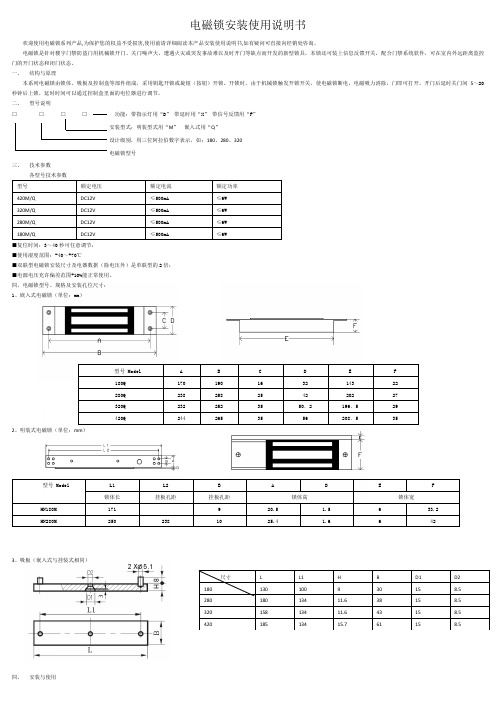
二、型号说明□□□□功能:带指示灯用“D”带延时用“X”带信号反馈用“F”安装型式:明装型式用“M”嵌入式用“Q”设计级别,用三位阿拉伯数字表示,如:180、280、320电磁锁型号三、技术参数型号额定电压额定电流额定功率420M/Q DC12V ≤500mA≤6W320M/Q DC12V ≤500mA≤6W280M/Q DC12V ≤500mA ≤6W180M/Q DC12V ≤500mA ≤6W■复位时间:3~40秒可任意调节;■使用湿度范围:-40~+70℃■双联型电磁锁安装尺寸及电器数据(除电压外)是单联型的2倍;■电源电压充许偏差范围+10%能正常使用。
四、电磁锁型号、规格及安装孔位尺寸:1、嵌入式电磁锁(单位:mm)型号 Model A B C D E F180Q 170 190 16 32 143 22280Q 238 258 25 42 202 27320Q 232 252 35 50.2 196.5 29420Q 244 265 35 56 208.5 352、明装式电磁锁(单位:mm)型号 Model L1 L2 B A D E F锁体长挂板孔距挂板孔距锁体高锁体宽HN180M 171 9 20.5 1.5 6 33.2HN280M 250 238 10 25.4 1.6 6 423、吸板(嵌入式与挂装式相同)尺寸L L1 H B D1 D2180 130 100 9 30 15 8.5280 180 134 11.6 38 15 8.5320 158 134 11.6 43 15 8.5420 185 134 15.7 61 15 8.5四、安装与使用1、控制盒的安装①安装方法:控制盒装在门的房间内侧面,锁头朝门外。
防火门电磁锁安装指南

防火门电磁锁安装指南防火门电磁锁作为一种重要的安全设备,在现代建筑中被广泛应用。
它可以有效地控制防火门的打开与关闭,提高安全性。
本文将为您介绍防火门电磁锁的安装指南,以确保正确、高效地安装。
一、材料准备在安装防火门电磁锁前,需要准备以下材料:1. 防火门电磁锁及其配件2. 电源线及连接器3. 电源适配器或电池组4. 电线钳、剥线工具等常用电工工具5. 螺丝刀、电钻等安装工具确保所有所需材料齐全,以便顺利进行安装工作。
二、确认安装位置在开始安装之前,需要确定防火门电磁锁的安装位置。
一般来说,电磁锁应该安装在防火门的边缘部位,确保其可以有效地控制门的关闭和打开。
同时,还要注意电磁锁与门框之间的间隙大小是否合适,一般应为3-5毫米。
三、安装步骤1. 预先确定安装孔位根据已确定的安装位置,用铅笔或其它标记工具预先标记出电磁锁的安装孔位。
确保安装孔位的准确性和对称性。
2. 打孔使用电钻和合适的钻头,在标记好的孔位上进行打孔。
孔的大小应与电磁锁的螺丝相匹配,使得安装牢固。
3. 安装电磁锁本体将电磁锁的本体通过螺丝固定在预先打好的孔位上,确保安装紧固并且牢固。
同时,在安装过程中要注意调整电磁锁的位置,使其与门框的对应位置相符。
4. 连接电源线根据电磁锁的接线要求,将电源线连接到电磁锁的指定接线位置上。
使用电线钳和剥线工具,确保电源线与电磁锁的接触良好,牢固可靠。
5. 连接电源使用电源适配器或电池组等电源设备,将其连接到电磁锁的电源线上。
在连接电源之前,应确保所使用的电源与电磁锁的额定电压和电流相匹配。
6. 调试测试安装完成后,进行电磁锁的调试测试。
先通过控制电源的开关,观察电磁锁的开合情况是否正常。
接着,操作防火门进行开关,检查电磁锁是否能够准确控制门的关闭和打开。
四、安装注意事项1. 安装过程中要注意安全,避免触电和意外伤害。
2. 若不确定安装操作,请寻求专业人士或技术支持的帮助。
3. 严禁私自改装、拆卸电磁锁,以免影响其功能和安全性。
弱电工程门禁电磁锁安装教程
弱电工程门禁电磁锁安装教程
前言:
门禁系统的安装最难的还是锁,锁的安装很重要,今天就重点介绍一下门禁电锁的安装。
正文:
一、外开门挂装(明装)磁力锁安装方法
三、嵌入式(暗装)磁力锁安装方法
内开门与外开门的嵌入式安装方法一致
对于木门来说,如果门挡边的尺寸够埋入锁主体的话,安装非常简单,只需挖一个合适的槽,锁埋进后锁上螺丝即可,一般的施工人员见锁就会安装。
铝合金门的门框一般都是空心的,针对这一特点,我们设计了两种安装方法。
A.内衬木块法(请参考图十、图十一):在门框里放入一块大小合适的木头作衬,再锁螺丝。
此种方法取材方便,安装简单。
在实际安装中大多采用这种方法。
B.利用安装配件法:此种方法是利用我们提供的配件(四孔铁板+U型铁),使安装更加简便。
图十
图十一
★安装注意事项
在做嵌入式安装时一定注意门挡边的尺寸要稍大于所选锁的尺寸。
四、玻璃门(配U型支架)安装方法
五、注意事项和常见问题及解决方法。
门禁磁力锁接线图及安装步骤
门禁磁力锁接线图及安装步骤
磁力锁:生强大的吸力紧紧的吸住吸附铁板达到锁门的效果。
只要小小的电流电磁锁就会产生莫大的磁力,控制电磁锁电源的门禁系统识别人员正确后即断电,电磁锁失去吸力即可开门。
因为电磁锁没有复杂的机械结构以及锁舌的构造,适用在逃生门或是消防门的通路控制。
其内部用灌注环氧树酯保护锁体。
目前电磁锁的吸力强度以LB表示(磅),测试的方法是静态加压。
所谓静态加压就是电磁锁通电后慢慢地逐渐增加对吸附铁板的拉力,当超出电磁锁的吸力时瞬间拉开吸附铁板,此ㄧ拉力的数据就是电磁锁的拉力值。
而且电磁锁与吸附铁板的作用力必须是面对面而且是直线加压,如此电磁锁的吸力才是最大。
吸附铁板因为长时间受电磁铁的磁力感应有可能被短暂磁化。
磁力锁的安装方法
外开门的表面安装方法
第一步:首先用螺丝刀打开盖板,再用六角扳手打边板,准备安装;
第二步:拿出安装纸板,将纸板沿着虚线折叠把纸板放到所需装锁的位置,然后把需要打孔的地方做上记号后打孔;
第三步:
A、继铁板的固定,将内六角螺丝插入继铁板中,把橡胶华司置与两片金属华司之间,然后套在内六角螺丝上。
将继铁板插入门上打的三个孔中,同时把香菇头从门的另一面插入,利用六角扳手将继铁板锁在门上;
B、边板的固定,把边板用两个半圆头螺丝固定在先前打孔的门框上(固。
防爆电磁锁的使用和安装
一、概述北京卓川电子生产的ZL.72-DS-30型防爆电磁锁(以下简称电磁锁),是根据中国煤炭统配总公司1991年67号文关于“井口安全门必须实行闭锁”的要求和GB3836.1-830爆炸性环境用防爆电气设备通用规定,煤矿用电气设备制造规程(65)有关规定及煤矿安一规程要求自行设计研制的。
防爆电磁锁要适用于煤矿矿井无瓦斯喷出的井口安全门闭锁装置中,作为闭锁装置的执行机构,实行安全门置锁功能。
还可用于煤矿井下无瓦斯喷出的井下配电峒室的闭锁,使用架线电机车运输的巷道及沿该巷道的主要机电峒室等处的井门闭锁。
亦可单独使用。
DS-30-1型防爆电磁锁矿用一般型结构,防护等级为IP54,其置锁,解锁动作速度快,行程大,可靠性高,性能稳定,抗砸强度好,工作电压范围广,且为间断式瞬间性工作台,耗电极省,同时它使用时勿需改变矿原来的工作方式,还可直接使用矿井的127伏、220伏交流电压,安装、使用、维修亦极方便。
二、型号含义三、技术参数1.防爆电磁锁的技术指标a、工作电压:127V 220V AC ;b、额定频率:50Hz;c、主锁工作电流:0.5A 解锁;付锁工作电流:0.35A 置锁;1.额定行程: 30mm;2.操作次数:500次/小时;3.额定动作时间:2分钟。
4.防爆电磁锁的使用环境条件a、海拔高度不超过2000m;b、工作环境温度-20℃—40℃;c、周围环境温度为25℃时,最大相对湿度为95%±3;d、在无剧烈颠簸振动及与垂直平面倾斜度不超过5°;e、在无甲烷和煤尘爆炸的场合;f、没有导电尘埃及足以能腐蚀金属和破坏绝缘的气体场合;g、无直接淋水的场合。
四、防爆电磁锁的外形及安装尺寸图1-1外形及安装尺寸五、防爆电磁锁的工作原理及电气接线(1)工作原理DS-30-1型电磁锁采用特殊结构,主锁副锁组成圈绕组,当主锁得到解锁信号时,产生强磁场吸引主锁芯后,由副锁将其锁住,实现解锁功能,当副线圈得到置锁信号时,吸引副锁芯,主锁芯自动释放,实现置锁功能。
防火门电磁锁安装步骤
防火门电磁锁安装步骤一、引言防火门电磁锁是一种常用的设备,用于保障建筑物的安全。
正确安装防火门电磁锁至关重要,本文将详细介绍防火门电磁锁的安装步骤,帮助读者了解该过程并确保安装质量。
二、材料准备在开始安装过程之前,需要准备好以下所需材料:1. 防火门电磁锁2. 电源线3. 控制线(如需要)4. 固定螺丝和螺母5. 按钮或遥控器(如需要)三、安装步骤1. 确定安装位置首先,根据需要,确定防火门电磁锁的安装位置。
通常情况下,电磁锁应该安装在门的上部,确保门能够有效关闭并保持防火性能。
2. 安装锁体将电磁锁的锁体固定在门的顶部。
使用螺丝和螺母将锁体牢固地固定在门上,并确保锁体与门框对齐。
确保螺丝牢固固定,以防止锁体在使用过程中松动。
3. 安装控制线根据需要,将控制线连接到电磁锁上。
将一端连接到门旁边的控制面板或按钮,另一端连接到电磁锁上的对应接口。
确保控制线连接牢固,无松动。
4. 连接电源线将电源线与电磁锁连接。
一般情况下,电源线应与电磁锁上的正负极相对应连接。
确保电源线连接正确,并进行绝缘处理,以确保安全使用。
5. 测试电磁锁在安装完以上步骤后,进行电磁锁的测试。
用控制线或按钮对电磁锁进行测试,确保锁体能够正常工作。
测试时应注意听电磁锁的工作声音以及观察锁体的工作状态,确保无异常。
6. 调试电磁锁如果发现电磁锁在测试过程中工作异常,需要进行调试。
检查控制线和电源线的连接是否正常,确保没有松动或接触异常。
如果问题持续存在,请联系专业技术人员进行进一步的检查和修理。
7. 加装按钮或遥控器(如需要)根据需要,可以在安装完成后加装按钮或遥控器,用于远程开关电磁锁。
将按钮或遥控器安装在门旁边或需要方便控制的位置,并与电磁锁进行连接。
确保按钮或遥控器的连接稳固可靠。
四、总结本文详细介绍了防火门电磁锁的安装步骤,包括准备材料、确定安装位置、安装锁体、安装控制线、连接电源线、测试电磁锁、调试电磁锁以及加装按钮或遥控器等内容。
- 1、下载文档前请自行甄别文档内容的完整性,平台不提供额外的编辑、内容补充、找答案等附加服务。
- 2、"仅部分预览"的文档,不可在线预览部分如存在完整性等问题,可反馈申请退款(可完整预览的文档不适用该条件!)。
- 3、如文档侵犯您的权益,请联系客服反馈,我们会尽快为您处理(人工客服工作时间:9:00-18:30)。
玻璃门安装法
一. 有铝合金(或其它材料)包框玻璃门的安装方法
玻璃门要做埋入式安装,无论你的门是内开式还是外开式、双开式自由门都可以安装。
玻璃门需要装有铝合金包框,因锁吸和距离要求小于6毫米,所以要求门边到门框的距离小于6毫米,地弹簧需采用品质稳定的,否则会影响锁的定位。
二. 无框玻璃门的安装方法
1. 利用U型支架安装磁力锁在无框玻璃门上:
没有包框的玻璃门需要有配件来辅助安装。
把U型槽连同橡胶缓冲垫及不锈钢垫片(放在锁螺丝的一边)套在玻璃门上,用无头内六角螺丝锁在玻璃门上,然后把继铁板固定在U型槽上。
对于不同的玻璃门厚度及不同型号的电磁锁,我们提供不同型号的安装配件。
2.利用AB架来安装先把AB架用玻璃专用胶(或双面胶带)固定在玻璃门上,然后再把继铁板固定在支架上。
安装后的样子一般用第一种(利用U型支架安装磁力锁在无框玻璃门上)
综上所述,王工,玻璃门分有框和无框两种,无论单开门双开门包不包框等那一种,我们都能安装上磁力锁。
我们可以跟他们这么配合,让他们定下什么样的门的样式来,我们准备配件配合他们安装没问题的。
只是门框安装的时候我们在场或者让他们从门框中间留出线来,我们就能安装好。
电锁安装图。