IQTL简易 操作指南
Cleveland Range T1 Skillet 安装和操作说明书

SE95051 Rev. 5Operators ManualInstallation & OperationElectric T1 Skillets1333 East 179th St., Cleveland, Ohio, U.S.A. 44110Phone: (216) 481-4900 Fax: (216) 481-3782Visit our web site at Cleveland™EnodisFOR MODELS BUILT AFTER MAY 2006:SEL-30-T1SEL-40-T1For a complete Service Manual refer to FOR THE USERIMPORTANTTHE INSTALLATION AND CONNECTION MUST COMPLY WITH THE LOCAL AND NATIONAL ELECTRICAL CODES.ENSURE ELECTRICAL SUPPLY CONFORMS WITH ELECTRICAL CHARACTERISTICS SHOWN ON THE RATING LABELALL SERVICE MUST BE PERFORMED BY A QUALIFIED CLEVELAND RANGE TECHNI-CIAN.RETAIN THIS MANUAL FOR YOUR REFERENCE.WARNING :Improper installation, adjustment, alteration, service or maintenancecan cause property damage, injury or death.Read the Installation and Operating instructions thoroughly beforeinstalling or servicing this equipment.!GENERALInstallation of the unit must be accomplished by quali-fied electrical installation personnel working to all appli-cable local and national codes. Improper installation of product could cause injury or damage.This equipment is built to comply with applicable stan-dards for manufacturers. Included among thoseapproval agencies are: UL, NSF , ASME/Ntl. Bd., CSA,CGA, ETL, and others. Many local codes exist, and it is the responsibility of the owner/installer to comply with these codes.Note:Maximum voltage for LVD (low volt directive for Europe) to be 440 volts for CE marked appliances.INSPECTION / UNPACKINGNote:The electrical rating label is located on the right console. Serial number, voltage, phase, amperage and wattage are stated on this label.1.Before unpacking visually inspect the unit for evi-dence of damage during shipping.2.If damage is noticed, do not unpack the unit, follow"SHIPPING DAMAGE INSTRUCTIONS" shown below.3.Carefully remove unit from shipping carton. Removeany packing material from unit. After carefullyunpacking check for "concealed" damage. If dam-age is noticed, follow "SHIPPING DAMAGE INSTRUCTIONS" shown below.4.Check the electrical rating label to ensure that theunit is the correct voltage, phase, amperage and wattage are stated on this label.5. A protective material has been applied to the stain-less steel panels. This material must be removed immediately after installation, as heat will melt the material and make it more difficult to remove.SHIPPING DAMAGE INSTRUCTIONSIf shipping damage to the unit is discovered or suspect-ed, observe the following guidelines in preparing a ship-ping damage claim.1.Write down a description of the damage or the rea-son for suspecting damage as soon as it is discov-ered. This will help in filling out the claim forms later.2.As soon as damage is discovered or suspected, noti-fy the carrier that delivered the shipment.3.Arrange for the carrier's representative to examinethe damage.4.Fill out all carrier claims forms and have the examin-ing carrier sign and date each form.CLEARANCE REQUIREMENTSThis unit must be installed in accordance with the clear-ances shown on the rating label which is adhered to the unit.FOR YOUR SAFETY . Keep the appliance area free and clear of combustible materials.INSTALLATIONNote:For clearance requirements, suggested drain location and assembly details refer to Specification Sheet.1.Position the unit in it's permanent location, and levelthe unit by turning the adjustable feet.2.Once positionedand leveled, per-manently secure the unit's rearflanged feet to thefloor using 5/16"lag bolts and floor anchors (suppliedby the installer).Three bolts arerequired to secure each of the flanged feet.3.Seal joints of flanged feet with a silicone sealant.INSTALLATION7/16"Ø, 3 HOLES ON 3 1/8" (80mm) B.C.D.FLANGED FOOT DETAIL(REAR LEGS ONLY )120120 4 7/8" (124mm)WIRE CONNECTIONNote:Ensure main power is turned off before connect-ing wires.General InformationInstall in accordance with local codes and/or the National Electric Code ANSI/NFPA No. 70-1990 (USA) or the Canadian Electric Code CSA Standard C22.1 (Canada). A separate fused disconnect switch must be supplied and installed. The unit must be electrically grounded by the installer.The electrical supply must match the power require-ments specified on the unit's rating label. The copper wiring must be adequate to carry the required current at the rated voltage. Wire must be suitable for at least 194°F (90°C). Refer to Specification Sheet for all electri-cal specifications. Cleveland strongly recommends the use of liquid tight fittings.ConnectionNOTE: Wiring diagram is located under the top cover of the unit's right console.ENSURE THE ELECTRICAL SUPPLY MATCHES THE UNIT'S REQUIREMENTS AS STATED ON THE ELEC-TRICAL RATING LABEL.The supply lines will enter through the bottom of the right console and are connected to the terminal block.WATER CONNECTION (OPTIONAL)A 1/2" NPT cold water line and/or a 1/2" NPT hot water line are required if unit is equipped with a single or dou-ble pantry faucet.INSTALLATION CHECKSAlthough the unit has been thoroughly tested before leaving the factory, the installer is responsible for ensur-ing the proper operation of unit once installed.1.Supply power to the unit by placing the fused dis-connect switch to the "ON" position.2.Turn Temperature Dial to 150°F (66°C).3.Toggle Power Switch to the "ON" position.4.Heat Indicator Light (yellow)should be ON and unitheating. When temperature is reached, YellowIndicator Light will switch OFF.7.Turn Temperature Dial300°F (150°C). Unit will con-tinue to heat, Heat Indicator Light (yellow)willremain ON until temperature is reached. Then theheat indicator light will cycle off indicating the heat-ing system has shut OFF. The heat indicator light will continue to cycle ON and OFF as the heating sys-tem cycles ON and OFF maintaining the desiredtemperature.3.Toggle Power Switch to the "OFF" position.CLEANINGAfter installation the unit must be thoroughly cleaned and sanitized prior to cooking. See “CLEANING INSTRUCTIONS”in this manual for complete cleaning instructions.OPERATING INSTRUCTIONSGeneral Parts DrawingITEM #DESCRIPTION FUNCTION1.Power Switch Lower position -power to the unit is OFF.Upper position -power to the unit is ON.2.Power Indicator Light (red)Indicates power is ON.3.Temperature Dial Regulates the surface temperature of the pan.4.Heat Indicator Light (yellow)Turns ON when system is calling for heat andOFF when system is satisfied.5.Hand Tilt Wheel Used for tilting the pan up or down.6.Power Tilt Switch Option - Used for tilting the pan up or down.7.Reset Button Fuse protection for optional power tilt.8.Manual Tilt Override Used on units with optional power tilt for tilting the pan up or downin case of power or mechanical failure.9.Faucet Option - hot and/or cold faucet mounts to skillet for(not shown)convenient filling of the pan.10.Tangent Draw-Off Valve Option - allows you to discharge product from the pan through(not shown)the valve.OPERATING THE UNIT1.Ensure electrical supply to the unit is in the ONposition.2.Turn Power Switch to the ON position. The yellowHeat Indicator Light will indicate power is on.3.MANUAL TILT: Cleveland skillets are equippedwith a manual tilt mechanism for raising and lower-ing the pan. To raise pan, raise the cover and turnthe crank clockwise. To lower pan, turn counter-clockwise.POWER TILT: Cleveland skillets can also beequipped with an optional electric power tilt mech-anism for raising and lowering the pan. To raisepan, raise the cover and press up on the tilt switch.To lower pan, press down on the tilt switch.4.FOR YOUR SAFETY: This skillet is alsoequipped with a power interrupter which automati-cally shuts of the power to the elements wheneverthe skillet is raised more than 1/2" (13mm).IMPORTANT:Before commencing to cook,ensure pan is in the lowered position by pressingdown on the tilt switch. Ensure cover is raised first.5.To preheat, set Temperature Dial to desired cook-ing temperature.6.Allow skillet to preheat for approximately 15-30minutes.7.Once preheated, insert product in skillet and adjustTemperature Dial to required cooking temperature.8.If desired, once product has cooked, it can be heldprior to serving at a lower temperature setting.9.When cooking is completed, set Temperature Dialand Power Switch to the OFF position.10.The best time to clean the skillet is immediatelyafter use, once skillet has cooled down. Refer tosection titled "CLEANING INSTRUCTIONS" fordetails.OPERATING SUGGESTION1.Turn power switch to the "OFF" position when skilletis not in use.2.Allow skillet to preheat before adding product.3.Always lift the spring assist cover before activatingthe tilt mechanism.4.During an electrical power interruption, turn PowerSwitch to the OFF position. This unit cannot bemade to operate without electrical power.12HOTOPEN LID BEFORETILTING PAN!Cooking equipment must be cleaned regularly to maintain its fast, efficient cooking performance and to ensure its continued safe, reliable operation. The best time to clean is shortly after each use (allow unit to cool to a safe temperature).WARNINGS➩➩➩➩➩3.Prepare a warm water and mild detergent solution inthe unit. 4.Remove food soil using a nylon brush.5.Loosen food which is stuck by allowing it to soak ata low temperature setting. 6.Drain unit.7.Rinse interior thoroughly.8.If the unit is equipped with a Tangent Draw-OffValve , clean as follows:a)Disassemble the draw-off valve first by turningthe valve knob counter-clockwise, then turning the large hex nut counter-clockwise until the valve stem is free of the valve body.b)In a sink, wash and rinse the inside of the valvebody using a nylon brush.c)Use a nylon brush to clean tangent draw-off tube.d)Rinse with fresh water.e)Reassemble the draw-off valve by reversing theprocedure for disassembly. The valve's hex nut should be hand tight only.9.If the unit is equipped with a Butterfly Valve , cleanas follows:a)Place valve in open position.b)Wash using a warm water and mild detergentsolution.c)Remove food deposits using a nylon brush.d)Rinse with fresh water.e)Leave valve open when unit is not in ing mild soapy water and a damp sponge, washthe exterior, rinse, and dry.NOTES➩For more difficult cleaning applications one of the fol-lowing can be used: alcohol, baking soda, vinegar, or a solution of ammonia in water. ➩Leave the cover off when the kettle is not in use.➩For more detailed instructions refer to the NafemStainless Steel Equipment Care and Cleaning manual (supplied with unit).STAINLESS STEEL EQUIPMENT CARE AND CLEANING (Suppied courtesy of Nafem. For more information visit their web site at )Contrary to popular belief, stainless steels ARE susceptible to rusting. Corrosion on metals is everywhere. It is recognized quickly on iron and steel as unsightly yellow/orange rust. Such metals are called “active”because they actively corrode in a natural environment when their atoms combine with oxygen to form rust.Stainless steels are passive metals because they contain other metals, like chromium, nickel and manganese that stabilize the atoms. 400 series stain-less steels are called ferritic, contain chromium, and are magnetic; 300 series stainless steels are called austenitic, contain chromium and nickel; and 200 series stainless, also austenitic, contains manganese, nitrogen and carbon. Austenitic types of stainless are not magnetic, and generally provide greater resistance to corrosion than ferritic types.With 12-30 percent chromium, an invisible passive film covers the steel’s surface acting as a shield against corrosion. As long as the film is intact and not broken or contaminated, the metal is passive and stain-less. If the passive film of stainless steel has been broken, equipment starts to cor-rode. At its end, it rusts.Enemies of Stainless SteelThere are three basic things which can break down stainless steel’s passiv-ity layer and allow corrosion to occur.1.Mechanical abrasion2.Deposits and water3.ChloridesMechanical abrasion means those things that will scratch a steel surface. Steel pads, wire brushes and scrapers are prime examples.Water comes out of the faucet in varying degrees of hardness. Depending on what part of the country you live in, you may have hard or soft water. Hard water may leave spots, and when heated leave deposits behind that if left to sit, will break down the passive layer and rust stainless steel. Other deposits from food preparation and service must be properly removed. Chlorides are found nearly everywhere. They are in water, food and table salt. One of the worst chloride perpetrators can come from household and industrial cleaners.So what does all this mean? Don’t Despair!Here are a few steps that can help prevent stainless steel rust.e the proper tools.When cleaning stainless steel products, use non-abrasive tools. Soft cloths and plastic scouring pads will not harm steel’s passive layer.Stainless steel pads also can be used but the scrubbing motion must be in the direction of the manufacturers’ polishing marks.2.Clean with the polish lines.Some stainless steel comes with visible polishing lines or “grain.”When visible lines are present, always scrub in a motion parallel to the lines. When the grain cannot be seen, play it safe and use a soft cloth or plastic scouring pad.e alkaline, alkaline chlorinated or non-chloride containing cleaners.While many traditional cleaners are loaded with chlorides, the industry is providing an ever-increasing choice of non-chloride cleaners. If you are not sure of chloride content in the cleaner used, contact your cleaner supplier. If your present cleaner contains chlorides, ask your supplier if they have an alternative. Avoid cleaners containing quaternary salts; italso can attack stainless steel and cause pitting and rusting.4.Treat your water.Though this is not always practical, softening hard water can do much to reduce deposits. There are certain filters that can be installed toremove distasteful and corrosive elements. To insure proper watertreatment, call a treatment specialist.5.Keep your food equipment clean.Use alkaline, alkaline chlorinated or non-chloride cleaners at recom-mended strength. Clean frequently to avoid build-up of hard, stubborn stains. If you boil water in stainless steel equipment, remember the sin-gle most likely cause of damage is chlorides in the water. Heatingcleaners that contain chlorides have a similar effect.6.Rinse, rinse, rinse.If chlorinated cleaners are used, rinse and wipe equipment and sup-plies dry immediately. The sooner you wipe off standing water, espe-cially when it contains cleaning agents, the better. After wiping equip-ment down, allow it to air dry; oxygen helps maintain the stainlesssteel’s passivity film.7.Never use hydrochloric acid (muriatic acid) on stainless steel.8.Regularly restore/passivate stainless steel.Recommended cleaners for specific situationsJob Cleaning Agent CommentsRoutine cleaning Soap, ammonia, Apply with cloth or spongedetergent, MedallionFingerprints & smears Arcal 20, Lac-O-Nu Provides barrier filmEcoshineStubborn stains & Cameo, Talc, Zud, Rub in direction of polish lines discoloration First ImpressionGrease & fatty acids, Easy-off, De-Grease Excellent removal on all finishes blood, burnt-on-foods It Oven AidGrease & oil Any good Apply with sponge or clothcommercial detergentRestoration/Passivation Benefit, Super SheenReview1.Stainless steels rust when passivity (film-shield) breaks down as aresult of scrapes, scratches, deposits and chlorides.2.Stainless steel rust starts with pits and cracks.e the proper tools. Do not use steel pads, wire brushes or scrapersto clean stainless steel.e non-chlorinated cleaners at recommended concentrations. Useonly chloride- free cleaners.5.Soften your water. Use filters and softeners whenever possible.6.Wipe off cleaning agent(s) and standing water as soon as possible.Prolonged contact causes eventual problems.To learn more about chloride-stress corrosion and how to prevent it, con-tact the equipment manufacturer or cleaning materials supplier. Developed by Packer Engineering, Naperville, Ill., an independent testing laboratory.。
ImageQuant TL 8.1操作指南说明书
ImageQuant TL 8.1操作指南引言●IQTL是一款多功能定量分析软件,能够对蛋白条带、克隆计数、96孔板进行定量分析。
对于工业用户,其对蛋白分子量及纯度的分析尤其适用。
●IQTL 软件对分析图片有一定的要求,要求图片由专业的分析成像设备拍摄,图片格式应为.gel或16bit .tif。
●若图片为8 bit RGB格式,即相机拍摄格式,需要用第三方软件(如photoshop)将格式转换为16 bit .tif灰度图像。
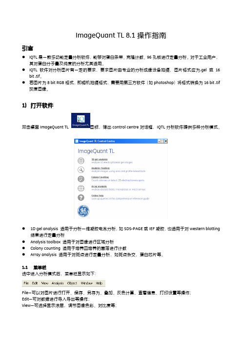
1)打开软件双击桌面ImageQuant TL 图标,弹出control centre对话框,IQTL分析软件提供多种分析模式。
●1D gel analysis 适用于分析一维凝胶电泳分析,如SDS-PAGE或IEF凝胶,也适用于对western blotting结果进行定量分析●Analysis toolbox 适用于对图像进行区域分析●Colony counting 适用于培养皿培养的菌落进行计数●Array analysis 适用于对斑点进行定量分析,如斑点杂交,蛋白芯片等。
1.1菜单栏选中进入分析模式后,菜单栏显示如下:File—可以对图片进行打开、保存、另存为、叠加、反色计算、查看信息、打印设置等操作;Edit—可对数据进行导入导出等操作;View—可选择显示涂层,调节图像色彩、对比度等;Analysis—选择图像分析步骤;Object—调整对象Window—调整窗口Help—帮助1.1.1图像叠加IQTL软件提供对相同大小图像进行叠加的功能。
要求需要叠加的图像在同一文件夹中,图像大小完全一致创建的叠加图片在同一文件夹中1)点击File—Create Multiplex Image2)弹出Create Multiplex Image对话框3)在Name中输入叠加后图片名称4)点击Browse,选择需要叠加的图片,点击open打开5)点击Create,创建图片,创建的图片格式为.ds。
IQ操作说明书

IQ操作说明书请确保完整阅读和理解本手册电动执行机构iq系列安装和维护手册出版物编号e170c2 出版日期2002.3. rotork设定器可按现场要求对执行器的控制、指示、保护功能进行设定。
所有的执行器在投入使用前,有必要检查其与过程控制系统要求的兼容性。
请阅读本手册。
当rotork工作人员或指定代理商按照合同规定进行现场调试和验收时,执行器组态的相关文件应让客户留档备查。
本手册提供如下介绍:* 手动和电动(就地和远程)操作。
* 执行器的准备和安装。
* 根据有关阀门正确操作的要求,对执行器进行初级设定。
* 根据现场具体控制和指示的要求,对执行器进行二级设定。
* 维护 - 故障排除。
* 销售和服务。
rotorkiq系列执行器- 全世界首家推出无需打开电气端盖即可进行调试和查询的阀门执行器。
使用所提供的红外线设定器进入执行器的设定程序,即使在危险区域,也可安全、快捷地对力矩值、限位以及其它所有控制和指示功能进行设定。
iq的设定和调整在执行器主电源接通和断开时均可完成。
标准诊断功能可对控制系统、阀门和执行器的状态进行诊断,并通过执行器的显示屏上的图标和帮助屏幕来显示。
按一下设定器的按键即可在显示屏上对相应阀位的瞬时力矩进行监视。
内置的数据记录器可获取操作和阀门力矩数据,可提醒用户根据需要对阀门进行维护。
运行于pc机的iq insight软件和/或rotork本安型通讯器可访问数据记录器,可对执行器的所有功能进行组态和记录。
执行器是否带有设定器,可根据接线端子箱盖上的黄色标签来识别。
目录5 执行器的安装10 11 11页码2 1 健康与安全5.1 提升杆式阀门 -顶部安装5.2 带齿轮箱的阀门 -7.6 检查方式 7.7 程序路径分支 -分支点 (cr) 7.8 执行器的显示18 19 192 保存3 iq系列执行器的操作3.1 手动操作 3.2 电动操作 3.3 执行器的显示 -阀位指示3.4 执行器的显示 - 报警指示4 准备驱动轴套4.1 iq7至iq35 a和z型推力底座 4.2 iq7至iq35 b型非推力底座 4.3 iq40至iq95 a和z型推力底座 4.4 iq40至iq95 b型非推力底座3 侧面安装5.3 非提升杆式阀门 -3 顶部安装3 5.4 手轮密封 3 5.5 iqm调节型执行器 4 5.6 iqml线性推力装置 5.7iqml线性行程的调整5 6 接线6.1 地线的连接 7 6.2 端子箱盖的拆卸 7 6.3 电缆入口 6.4 端子的接线 76.5 端子箱盖的复位 7 设定8 7.1 设定程序 7.2 设定器97.3 进入设定程序 7.4 设定方式 - 口令 7.5 新口令1设定 / 检查方式 117.9 返回阀位指示11 8 设定 -12 初级设定功能12 初级设定功能目录1214 9 设定 -14 二级设定功能14 二级设定功能目录14 10 维护和故障排除15 10.1 帮助显示 15 10.2 irda诊断和组态1616 11 重量和尺寸1718 二进制、十六进制、十进制 18 换算表1819 20 213030 61 63 68 7071篇二:iq350说明书1. 便携式气体检测仪2. 量程:0-3%(20、50、100、200、500、1000ppm或更高浓度 %lel选择,由业主确定)3. 最小分辨率: 0.01 % (0.1、1.0ppm由厂家根据测定的范围而确定)4. 运行温度:-20-50℃5. 湿度:0-95% (无凝结水)6. 报警:内设报警装置(声、光)7. 显示:高清晰数字显示 8. 取样方式:内置取样气泵9. 电力:8、或14小时的电池选择10. 充电器:外接充电器11. 尺寸(mm):181.1х85.9х101.6 12. 重量(kg):1.1kg(包括电池)特性:电源:4c 碱性或镍镉电池碱性电池: 24小时镍镉电池: 12 小时标准可用气体:二氧化碳:2000ppm,1%体积百分数,10%体积百分数碳氢化合物:10,000ppm,100%lel,100%体积甲烷氧气:25%体积百分数一氧化碳:1%体积百分数或更高对于所有气体要求有其它可用的量程其它可用气体:乙醛、丙酮、丙烯醛、苯、丁烷、环己胺、二乙基胺、二甲胺、乙烷、乙醇、乙烷基苯、乙撑氧、甲醛、氟里昂152、氟里昂134a、四氟甲烷、庚烷、甲醇、丙烷、苯乙烯、二甲苯等传感器:二氧化碳(co2)和碳氢化合物(hcs):红外线传感器氧气(o2):长寿命电化学传感器指示器:低、高报警发光二极管指示,工作发光二极管指示,低电池发光二极管指示,泵发光二极管指示。
iQ5荧光定量PCR仪操作软件

iQ5荧光定量PCR仪操作手册iQ5荧光定量PCR仪监控软件操作程序接通光学检测部分的电源,实验前先让系统预热30分钟,打开iCycler扩增系统(即仪器的基座),打开电脑,(显示windows XP或2000界面),双击iQ5的软件,启动。
iQ5软件有5个模块,每个模块的图像始终显示在屏幕的左侧,激活的模块背景为橙色,未激活的模块背景为灰色,每个模块再细分有此模块下的功能视窗。
1.Workshop(工作模块):用于设计反应板、程序及运行实验,选择实验文件,打开以往反应数据(用于分析)。
Workshop模块包括Setup(设置)和Plate Summary(板设置概要)视窗。
Setup(设置)视窗下有4个窗口:Protocol(程序)、Plate(板)、Run Set(运行设置)和Data File(资料文件),用于选择、打开、编辑或创建新文件。
在Setup(设置)视窗下,选择的Protocol(程序)和Plate(板)设置可以Run(运行),或者选择的Data File(资料文件)可以被打开在Data Analysis(资料分析)视窗中进行分析。
2.Run-Time Central(运行-实时监测中心模块):这个模块用于启动和监测实验运行。
当Protocol和Plate设定好之后,点击Run(运行)或Run End Point(终点运行)。
3.Data Analysis(数据分析模块):这个模块包含一系列工具,可以让你对实验数据进行多种分析。
在这个模块中显示Quantitative(定Alleliclic 量)、Melt Curve/Peak(融解曲线/峰)、End Point(终点)、Alle Discrimination(等位基因区分)和Gene Expression(基因表达)分析。
板编辑界面允许实验运行结束后进行板的设置,允许更正不正确的样本设置。
当你从Workshop打开一个已保存的数据文件,Data Analysis会自动打开。
操作手册IQ2 FF简易版-喉式金检

LOMA IQ2自由落体式金属检测机操作步骤操作手册一、开机前准备:1、检查机器所要接的电源是否正确2、有气源的机器气源是否接通3、对机器进行预热30分钟以上4、开始检测产品时,用测试条测试精度有无变化,有则重新设置产品二、设置产品需要设置的同项内容:1、设置编号2、设置名称3、设置剔除时间4、设置最小阀值5、设置探头功率6、设置完全校准7、设置按键密码注:以上操作下面将做逐个介绍。
三、各按键作用确认键或上下键结果键校准键设置键产品转换键锁定键(密码锁)返回键或左右键四、各指示灯作用:运行指示灯系统故障指示灯校准指示灯运行错误指示灯五、产品设置(Product Setup)1、设置产品编号(Product No.)按一次设置键,找出Product Setup产品设置,找到后按一次确认键;找Product No产品编号.,找到后按一次确认键,再按上键和下键选择所需要的数字编号,按一次确认键,再按返回键两次返回数字界面。
2、设置产品名称(Name)按一次设置键,找Product Setup,找到后按一次确认键,按下键找到Name,然后按一次确认键,按上键和下键找到相应的字母,每找到一个合适的字母按一次确认键,输入完名称字母后,继续按确认键直到前面的箭头消失后,机器系统会自动存储该产品名称,按返回键两次返回到数字界面。
3、设置剔除延时(Reject Delay)按一次设置键,找Product Setup,按下键找到Reject Delay,按一次确认键,出现一个向右的箭头,这时按选择相应的数字值(这个数值是由测试条通过检测头停留位置和收缩下落位置来确定这个时间数字值),最后按一次确认键。
按返回键返回到数字界面。
对自由落体式金检机,无剔除延时时间。
4、设置剔除动作时间(Reject Delay)按一次设置键,找Product Setup,按下键找到Reject Dwell,按一次确认键,出现一个向右的箭头,这时按上键和下键选择相应的数字值(这个数值是由测试条通过检测头收缩后停留时间的长短,在剔除方式为停机报警的机器中是用不到这一项的),按一次确认键,等到右箭头消失,按返回键两次返回到数字界面。
IQsignal中文操作手册

发射测试结果(1)
单次测 试结果 信号波形 信号平均功率 平均测 试结果
红色线为 均值波形
底噪
(重点关注指标)试结果(2)
频谱模板
蓝色谱线不 能超出红色 限制线
功率幅度 统计图 判定产品功放 是工作在饱和 区还是线性区 (读数如箭头所 示) 蓝线紧贴红 线代表产品 工作在线性 区,两线分 离较大代表 产品功放在 饱和区工作
测试数据显示区
选择中间图 表显示内容
选择左下方图 表显示内容
选择右下方图 表显示内容
IQsignal软件界面——VSG界面
选择Tools->Vector Signal Generator即可进入 信号单次 发射按键 信号连续 发射开关 选择连续发射 或一次性发射 数据包数量 选择射频信号或 基带信号输出 设定频道和调制 方式(速率)
电脑IP设定步骤
本地连接---Internet协议---写入IP及子网掩码---(高级---添加---写入 IP及子网掩码--)确定---确定(若只需设定一个IP则不需进入高级选项)
IQsignal软件中的仪器IP地址设定
打开IQsignal软件,若提示错误如右图所示, 则可能是软件中的仪器IP地址设定不正确,应 按以下步骤写入正确的仪器IP地址:
接收测试
产品控制软件选择测试项目为Rx
设定要测试的频道 和速率
IQsignal的VSG界面设定频道与上面一样
设定VSA的调制方式 性发射数据包数量
、功率
和一次
点击产品控制软件的 ,点击VSA的 之后观察产品控制软件的接收数据包统计数据
接收测试结果
接收到的良好 数据包数量
本例中仪器VSG发射了1000个信号强度为-50dBm的数据包,接收到良好的 数据包数量为 912 ,故PER为 (1000-912)/1000 = 8.8% <10% 因此可证明,在-50dBm的信号强度下产品接收能力良好。(对于11b调制方 式,PER界限为8%) 然后降低仪器VSG信号功率,数据包统计数量复位清零 ,重复上页第 5 项操作,直至接收到良好数据包数量小于900,即 PER>10% ,则可初步 判定产品的接收灵敏度界限值(是否达到要求)。 更改频道和速率,重复上述操作,测试产品在不同频道速率的接收能力情况。 可绘制出PER与信号功率的关系曲线图,便于全面了解产品接收能力情况。
LAS4000mini简易操作指南
ImageQuant LAS 4000 mini 化学发光成像仪简易操作指南开机1. 启动LAS 4010机箱电源、个人计算机和控制软件ImageQuant LAS 4000;2. 等待数分钟:当CCD达到预设温度后,温度栏显示READY,设备即可随时使用。
化学发光成像1.将一参考物(例如有字的纸)置于EPI 样品盘内,根据样品大小,放入机箱合适位置(<105x 70mm置于顶层1号位,可根据样品盘上暗点确定位置),关闭机箱门。
2.点击控制软件Method/Tray position 按钮。
a)在Method纵向栏中选择化学发光Chemiluminescence。
b)根据样品盘实际位置选择Tray position。
c)点击OK。
3.点击聚焦Focusing 按钮。
进行精细聚焦。
完毕后点击返回Return 按钮。
4.在主界面Exposure Type菜单中选择单张曝光Precision。
5.在曝光时间Exposure Time菜单中选择自动曝光Auto或者手工设定Manual。
如果选择手工设定,继续设置曝光时间(1/100秒到30小时)。
6.在Sensitivity/Resolution菜单中选择灵敏度/分辨率,推荐标准Standard。
7.取出参考物。
A、B液孵育转印膜,将转印膜置于EPI 样品盘内,放入机箱,关闭机箱门。
8.点击开始Start 按钮,开始图像采集。
9.图像采集结束后,调整图像对比度gradation观察。
10.保存或者打印图像。
推荐16位tiff格式。
Save selected images:保存单张或多张图像,最多保存16张。
Save displayed images: 保存呈现在Index窗口中的图像,最多保存16张。
Save passed images:拍摄图像超过16张时,保存倒数第16张以前的图像,最多保存84张。
白光反射成像1. 将凝胶或膜置于反射EPI样品盘内,放入机箱,关闭机箱门。
iCycler iQ荧光定量PCR仪的操作说明

iCycler iQ TM荧光实时多波长PCR检测系统操作说明iCycler iQ TM Multi-ColorReal Time PCR Detection SystemOperating InstructionsCatalog Number170-8740如与英文版说明书有不符之处以英文版说明书为准2.iCycler iQ TM荧光实时多波长PCR检测系统操作速成2.1 简介:iCycler iQ TM荧光实时多波长PCR检测系统可以最多一次检测96个样品,且每个样品中同时可以检测4个不同波长的荧光信号。
也就是说,只要标记不同荧光探针,iCycler可以对同一个孔中两种以上的PCR产物(最多四种)同时进行实时分析。
这样对多重PCR反应或使用内对照(Internal Control)定量的PCR 反应的检测就十分方便。
在反应过程中,不同的荧光信号通过与其匹配的不同波长的滤光镜组来检测。
比如,在一个反应管中同时有四种荧光探针共存,分别标记了FAM、HEX、Texas Red®和Cy TM5,在收集其荧光信号数据的时候,必须同时使用FAM滤光镜组、HEX滤光镜组、Texas Red滤光镜组和Cy5滤光镜组。
所有的收集的信号由iCycler的软件进行分析整理,在PCR反应结束后,该软件可以显示其各自的荧光曲线和标准曲线,并得到这四种荧光探针分别对应的靶DNA的定量结果。
在每次使用iCycler进行PCR荧光定量实验之前,系统必须获得孔间差异因子(Well Factor)和纯染料校准(Pure Dye Calibration)的数据。
系统通过这些数据来区分不同的荧光信号,矫正孔间的误差。
本章节将详细的介绍这两者的调节方法。
您在使用本仪器前请先仔细阅读本章的内容,这将有助于您能够快速地完成实验并获得理想的实验数据。
2.2:iCycler操作速成1.开机前先让摄象系统预热30分钟。
接通iCycler的电源,并连上电脑,打开iCycler的软件。
- 1、下载文档前请自行甄别文档内容的完整性,平台不提供额外的编辑、内容补充、找答案等附加服务。
- 2、"仅部分预览"的文档,不可在线预览部分如存在完整性等问题,可反馈申请退款(可完整预览的文档不适用该条件!)。
- 3、如文档侵犯您的权益,请联系客服反馈,我们会尽快为您处理(人工客服工作时间:9:00-18:30)。
IQTL 7.0简易操作指南1D Gel Analysis************************************************************ # 点击【1D gel analysis】,点击【OPEN】打开图像;# 在【一维凝胶分析】中,一共可分为5个步骤,它们分别是创建泳道【Lane Creation】、消减背景【Background Subtraction】、蛋白条带检测【Band Detection】、分子量计算【Molecular Size Calibration】以及含量校正【Quantity Calibration】或者含量归一化【Normalisation】;# 在图像分析之前,首先需要对图像进行一些调整,去除无需分析的凝胶部分如上样孔和边缘,对图像进行旋转、调节图像对比度等。
点击【常用工具栏】上的【Edit Image】图标,进入图像编辑界面。
【Invert display】从而使图像变为【反色】效果(即黑变白、白变黑效果),从而增加图像的反差。
自动分析#只要点击左侧的【Automatic】按钮,程序便自动完成三步的分析:【创建泳道】、【消减背景】以及【蛋白条带检测】;#自动分析完成后,程序的左侧便自动的切换至【快速分析工具栏】;可以对每个步骤进行更详细的调整和修改;手动分析#【Stepwise】进入手动分析步骤,首先是【创建泳道】。
选择【Automatic】模式并点击【Create】按钮,程序会自动创建出合适数量的泳道,点击【Accept】接受该结果,点击【Clear】可以清楚创建泳道的结果;如果选择【Manual】模式,可以在【导航箭头】下面的【Parameters】中设置相关的参数,如泳道数量【Number of Lanes】等,在图像上拖动鼠标就可以按照设置创建出所需的泳道;# 如果需要对已经创建的泳道进行调整,可以在【编辑模式】下来框中选择【Edit Multiple Lanes】或者【Edit Single Lanes】进行调整;# 选择【Edit Single Lanes】,点击【Bend/Resize】可以调整泳道宽窄;同时,如果电泳泳道弯曲,我们可以在电泳泳道上点击【鼠标左键】为泳道增加一个或多个弯曲节点,拖动该节点可以弯曲【泳道检测线】使之符合实际泳道的形状;如果设定的节点不合适,也可以通过【右键】单击该节点进行删除;# 点击【Move】并拖动泳道移动该泳道;选择【Add Grimaces】可以调整泳道的弯曲效果;调整完毕后,点击【Accept】对接受所做的修改;************************************************************* # 完成创建泳道后,点击【导航栏】上的【Next】按钮进入到【消减背景】步骤;# 在【Image Window】中,选中的泳道显示为绿色,同时在右侧的【Lane】泳道窗口中可以看到以实线表示的该泳道的峰形图,峰型图下的紫色实线为背景基线,在此背景基线之下的部分都被程序认为是背景;# 在【导航栏】下面的【Parameters】中有多种背景消减的算法,其中在99% 以上的情况下,我们都使用【Rolling Ball】滚球算法作为背景消减的方法;# 选中【Rolling Ball】,可以通过上面的滑动块调节滚球的半径【Radius】使背景基线(紫色实线)能够尽可能的与背景重合,不同的图像设置的【Radius】的值有所不同。
点击【Subtract】按钮就完成了对图像背景的消减操作;# 【Minimum Profile】方法是以峰形图灰度最低值做一条平行于底边的实线作为背景值;【Image Rectangle】方法是在图像上选择一定区域并以该区域中像素灰度的平均值作为背景值,这一方法要求图像背景灰度分布均一;【Manual Baseline】是通过手动调节背景基线,这些方法都不能保证条带比较时的平行性,因此,一般情况下不建议使用;# 进行完【消减背景】操作后,点击【Next】进入下一步【条带检测】。
************************************************************* # 在【条带检测】步骤中,点击【Detect】进行自动条带检测。
滑动【Minimum slope】下的滑动块,可以调节条带检测的最小斜率。
该值越小,检测到的条带数量越多;反之,该值越大,检测到的条带数量越少;# 还可以通过【Parameters】中的参数对条带检测做一些精细的调节,包括噪音消减【Noise reduction】及最高峰百分比【%Max.Peak】。
改变【Noise reduction】的数值可以调整噪音的阈值,随着数值的增大,检测到的条带数量逐渐减少;改变【%Max. Peak】的数值可以调整条带强弱的阈值,随着数值的增大,检测到的弱带数量逐渐减少。
在一般情况下,使用软件的默认值;# 通过选择【Edge parameters】中的【Automatic detection】选项可以让软件自动寻找条带的边缘;# 也可以手动增加或减少条带,在【Image Window】中,检测到的条带中心是用【蓝色小菱形】显示的,【右键】单击该菱形可以取消该条带,【左键】单击可以增加条带;# 在进行完条带检测后,我们就可以进入到下一步【分子量计算】;************************************************************ # 点击【Next】进入到【分子量计算】界面,在【Parameters】中的【Standard】下拉框中可以选择程序内置的分子量Marker,也可以点击【Edit】按钮进入【编辑Standard】对话框编辑或新建自己的Standards;# 点击左下角第一个【编辑/新建Standard】按钮,输入新建Standard的名字,并在右侧的下拉菜单中选择分子量Maker的种类,如【Molecular Weight (KD) 】,在下面的【Mapping List】中双击【鼠标左键】,从高分子量至低分子量依次输入Standards的具体数值,点击【Done】完成Standards的创建或编辑;#根据分子量Marker的类别选择【Curve Type】的种类,并选中【Use Rf to propagate】。
这时在图像中跑有分子量Marker的泳道上单击左键,会出现几条黄色Marker线,通过调整Marker线的位置使Marker 线与真正的Marker重合,点击【Compute】按钮,计算结果显示在下方的【Measurement Window】的MW列中,点击【Selected Lane】、【All Lanes】与【Comparison】来查看不同泳道及条带的分子量详细信息;************************************************************* #条带的含量进行计算,含量校正【Quantity Calibration】及归一化【Normalization】。
【Quantity Calibraiton】是利用多个已知含量的条带创建一条拟合的标准曲线,并根据该标准曲线计算出其他条带的含量;而【Normalization】是设定一个条带的含量为100,其他条带根据与该条带的比例计算出相对含量。
这里需要特别说明的是,含量校正与归一化是两种不同的含量计算方法,不能同时使用!# 在【Quantity Calibration】步骤中,【左键】单击已知含量的条带,在弹出的空白框中输入含量的数值,如200,这时在【导航栏】下面的列表中就会显示该条带的含量,依次类推可以输入其他已知条带的含量。
选择【Force through Origin】使校正曲线通过原点,在该选项下的下拉列表中可以选择含量的单位。
# 设置完所有参数后,点击界面左上角的【Calibrate】可根据校正曲线对其他蛋白条带的含量进行计算,计算后的结果会显示在【Measurement Window】中的【Calib Vol (ug) 】项目中;************************************************************* # 归一化【Normalization】操作。
在【导航栏】下面的【Parameter】中设置标准含量蛋白的数值及单位,默认为100 microgram,选择【Normalization】的方式,根据average vol. 或者 collective vol. 完成设置后,【左键】单击标准化的蛋白,这时条带上的菱形由蓝色变成了黄色。
点击左上角的【Normalise】按钮,就可以对所有条带进行含量的归一化。
# 归一化的结果会显示在【Measurements Window】中的【Norm Vol (ug) 】项目中;************************************************************* # 在【一维凝胶分析】的各个步骤,我可以通过点击【常用工具栏】上的【Options】按钮进入设置选项,在不同的标签页中,如【Image】、【Analysis】、【Table】、【Lance Selection】、【Reporting】,设置需要显示的内容和偏好;# 同时,对于在分析过程中的所有结果,可以通过点击【Edit】菜单下的【Export to Excel】就可以直接将数据如【Measurements Window】中的数据导出至Excel电子表格。
Array Analysis*********************************************************************** # 对于微阵列(Microarray)、酶标板或者点杂交(Dot Blotting)的实验结果,可以使用【阵列分析】Array Analysis来进行分析;# 在IQTL【控制中心】点击【Array Analysis】,选择要分析的图像,点击【Open】就进入到【阵列分析】的界面;# 阵列分析一般包括定义点【Spot Definition】、消减背景【Background Subtraction】、含量归一化【Normalisation】和存在性判别【Presence Flagging】四个步骤。
#【Spot Definition】。
点击【Create & Strecth Grids】,在【Parameters】中选择网格类型【Grid Type】。