apit700说明书
康气通type700说明书

康气通type700说明书康气通Type700是一种理疗仪器,专为改善人体健康而设计,采用了先进的技术和原理。
本说明书将为您详细介绍康气通Type700的使用方法、功效以及注意事项,帮助您更好地了解和使用该设备。
一、产品简介康气通Type700是一款便携式理疗仪器,用于促进身体健康和舒缓疼痛。
它采用微弱电流和电磁波结合的方式,通过刺激和调理人体的经络系统,达到舒缓疼痛、促进血液循环、缓解疲劳的效果。
二、产品使用方法1. 准备工作:将康气通Type700插入电源适配器,并连接适当的治疗仪具或贴片。
2. 开机及设置:按下电源开关,并根据自身需求选择合适的模式和强度。
3. 使用操作:根据个人需要选择治疗仪具或贴片,然后将其贴附或安放在需要治疗的部位。
轻轻调整设备的强度,逐渐感受到微弱电流和电磁波的作用。
4. 结束治疗:治疗时间一般为15-30分钟,取决于个人需求。
结束后,先关闭设备,然后将治疗仪具或贴片取下。
三、产品功效康气通Type700具有多种功效,包括但不限于以下几个方面:1. 缓解疼痛:通过电流和电磁波的刺激,可以改善局部血液循环,缓解肌肉酸痛和关节炎引起的疼痛。
2. 改善血液循环:理疗仪器可以促进血管扩张,增加血液供应,改善血液循环,保持身体健康。
3. 改善睡眠:康气通Type700的治疗模式可调节神经系统,放松身心,帮助改善睡眠质量。
4. 缓解疲劳:经过使用,身体疲劳的感觉将减轻,焕发出新的活力。
5. 提升免疫力:理疗仪器可以调整免疫系统功能,提升身体免疫力,抵抗疾病。
四、产品注意事项1. 在使用康气通Type700前,请认真阅读说明书并按照指示进行操作。
2. 使用前请确保设备及仪具的清洁卫生,避免受到污染。
3. 对于孕妇和心脏病患者等特殊人群,请在专业人员的指导下使用。
4. 在使用过程中,如果出现异常情况如过敏反应、不适,请立即停止使用并就医。
5. 请勿将康气通Type700浸入水中或放置在潮湿的环境中。
恩伊阿卡瓦米特700极端商品说明说明书

Eni Aquamet 700 EXTREME is a cutting fluid with excellent technological characteristics, free of bactericide and boron, formulated with EP, anticorrosive, anti-rust and detergent agents. Particularly suitable for severe cutting operations such as: deep drilling, tapping, threading and MAPAL boring on aluminum and its alloys, steels and stainless steel, yellow metals; it is not suitable for machining cast iron.The particular formulation makes the product suitable also in light plastic deformation operations on aluminum and steel sheets.•Free of bactericide, boron and secondary amines for a lower ecotoxicological impact and better condition of the working environment•Excellent cutting, cooling and lubricating capacity for less tool wear and better surface finishing of the workpieces•Low foam formation, even under high pressure delivery and in a wide range of water hardness (optimal range: 15-40°F)•Excellent emulsion stability, reduction of the frequency of maintenance operations •Particularly suitable for machining aluminum and its alloys•Excellent detergent property to maintain clean the machine tool, equipment and workpieces•ISO 6743/7 MADProperties Method Unit TypicalCharacteristics of the concentrateAppearance--clear Density at 20°C ASTM D 1298kg/m³950 Characteristics of the emulsionEmulsion appearance (3%, water 20°F)--milkypH emuls. 3%ASTM D 1287-9.0 Corrosion on paper DIN 51360-pass at 5% Corrosion IP 125-pass at 5% Refractometric factor-- 1.0•Before preparing the emulsion, it is necessary to carry out adequate cleaning of the tank and the circuits of the machine tool with suitable products•Prepare the emulsion using possibly an emulsifier•In case of manual mixing, it is recommended to add the product in the water slowly and shaking the mixture, never vice versa, to avoid problems of emulsion instability •Store the product in closed warehouses at temperatures between +5 and +30° in order to prevent product deterioration, due to thermal shocks•Monitoring of the working emulsion is recommended in order to ensure the emulsion performances in the time and to prolong its useful life•More detailed information will be provided by the Eni Technical Assistance Service.•Here below are reported the recommended concentrations; however the actual concentration will be defined according to the specific operative conditionsDue to the complex nature of aluminum alloys, we advise to check always the stain test before any processing.Processing Steel, Steel Inox Aluminum and Alloys Copper and Alloys Turning, Milling5%6%5%Boring, Drilling6%6%6%Deep Drilling, Tapping,Threading8%8%8%Mapal Boring on Aluminum8%。
渔船Aqua TROLL 700商品说明手册说明书

Box Contents1Install the RDO Cap (RDO sensor only).Remove the restrictor.Use included hex wrench to loosen set screw on RDO e the small hole at the bottom of the sensor to lever the sensor out.Remove the dust cover from the RDO sensor.Install the RDO cap onthe sensor.Insert RDO sensor in instrument sensor port.Tighten screw at base of sensor with hex wrench. Do not overtighten.1. Instructions2. Instrument with sensors and wiper or wiper plug installed3. Hex Wrench4. Screwdriver5. RDO Sensor Cap (if RDO Sensor is included)6. pH/ORP or ISE Sensors (if selected)7. Accessories8.pH maintenance kit (if pH/ORP or ISE sensors are included)268715434Connect the Rugged Cable and communication device.2Install the pH/ORP Sensor or ISE sensors.3Prepare Instrument for Deployment.Remove protective caps from instrument and cable.Align the flat edges of the instrument connector and the cable.Slide connector into the cable end.Apply a pea-sized drop of grease to the O-ring.O-ring(Optional) Installrestrictor with vent holes at base of instrument for calibration.(Optional) Calibrate sensors. Calibration procedures may be found in user manual.After calibration, flip the restrictor with the vent holes away from the center of the instrument.Install the end cap on the restrictor fordeployment.Insert sensor into empty sensor port.Tighten screw at base of sensor with hex wrench. Do not overtighten.Apply a pea-sized drop of lubricant to sensor O-rings.Remove tape and capfrom sensor.Twist and push the sleeve until you hear a click.clickIf desiccant is present, remove it from cable.Align TROLL Com connector with cable end. Push and twist until you hear a click.You must have the VuSitu mobile app to use the instrument with a mobile device. Download VuSitu from the Google Play Store or the Apple App Store.5Connect to the software.6Learn more.VuSitu’s on-screen instructions will guide you through instrument calibration, live readings and Get complete instructions about calibration, logging and working with data in the product manual. Download it from .Tap the serial number of the instrument or Wireless TROLL Com.VuSitu displays the Connected Instrument screen when pairing is complete.cdLaunch VuSitu and tap Connect .The app locates and displays nearby In-Situ devices.An iOS deviceautomatically connects to the closest In-Situ instrument.To connect to another instrument, press Disconnect and then Choose or Add Device . VuSitu displays a list of available connections.aabb700Aqua TROLL 700Safety• Do not use the Aqua TROLL 700 in any manner not specified by the manufacturer.• Do not submerge the Twist-Lock connector ends of the cable or instrument when they are not connected.• Do not submerge the Wireless TROLL Com or your mobile device in liquid.• Ensure that sensors or sensor plugs are completely inserted into all ports so that no liquid can enter the instrument.• Ensure that the RDO Sensor Cap is pressed firmly over the sensor lens and is flush with the instrument before submerging in liquid.• Replace the cable if insulation or connectors are damaged.• Make sure the probe and sensor O-rings are clean and free of damage.Intended UseThe Aqua TROLL® 700 Multiparameter Sonde is designed to be safe:• during indoor or outdoor use• in ambient temperatures from -5 to 50° C • above or below 2000 m • in any relative humidity levels.安全• 请勿以制造商未指定的任何方式使用 Aqua TROLL 700。
wintop x700说明书
wintop x700说明书
1.密封性:采用电池槽盖、极柱双重密封设计,防止漏酸,可靠的安全阀可防止外部H2、O2和尘埃进入电池内部。
2.免维护:H2O再生能力强,密封反应效率高,因此在整个电池的使用过程中无需补水或加酸维护。
3.安全可靠:无酸液溢出,可靠的安全阀的自动闭合,防爆设备的装置使赛能电池在整个使用过程中更加安全可靠。
4.长寿命设计:计算机精设计的耐腐蚀铅钙铅合金板栅、ABS 耐腐蚀材料的使用和的密封反应效率保证了蓄电池的长寿命。
5.性能高
(1)体重比能量高,内阻小,输出功率高。
(2)充放电性能高,自放电控制在每个月2%以下(20℃)。
(3)恢复性能好,在深放电或者充电器出现故障时,短路放置30天后,仍可使用均衡充电法使其恢复容量。
(4)由于单体电池的内阻、容量、浮充电压性好,因此电池在浮充使用状态下无需均衡充电。
6.温度适应性强:可在-40℃~50℃下安全、放心地使用。
7.使用和运输安全简便:满荷电出厂,无游离电解液,电池可横向放置,并可以无危险材料进行水、陆运输。
8.性价比高:蓄电池的性能,超长的使用寿命,极低的维护成本确保用户得到的是性价比非常高的产品。
美国APIT700校准仪含臭氧发生器模块

套
24
用电开户
材料费(电表、电线、配电箱)
套
25
运输费用
新建站点设备运输费
套
26
三年托管运维服务
科迪隆技术服务
年
27
UPS 不间断电源
山特 UPS 不间断电源: 20KVA 主机一台,电 池组 32 节(100AH12V)
套
合计
二、其他项目详列
1 ¥1,800.00 ¥1,800.00 1 ¥56,100.00 ¥56,100.00 1 ¥21,000.00 ¥21,000.00
广东旭诚 AQMS 数据采集系统
套 1 ¥55,517.00 ¥55,517.00
12
站房
科迪隆 ZF-CGB15 站房
套 1 ¥184,480.00 ¥184,480.00
13
采样总管装置
科迪隆自动加热温控、内衬特氟龙材料 套 1 ¥26,520.00 ¥26,520.00
14
机柜(包括导轨配件)
3 ¥12,000.00 ¥36,000.00
2 ¥4,800.00 ¥9,600.00 1 ¥7,500.00 ¥7,500.00 1 ¥6,600.00 ¥6,600.00 1 ¥51,000.00 ¥51,000.00 1 ¥4,080.00 ¥4,080.00 1 ¥10,203.00 ¥10,203.00 3 ¥138,000.00 ¥414,000.00
科迪隆 38U 机柜(包括导轨配件)
套 1 ¥11,220.00 ¥11,220.00
15
超声波气象五参数
芬兰维萨拉 WXT536 超声波气象五参数(带 RG13)
套
1 ¥70,380.00 ¥70,380.00
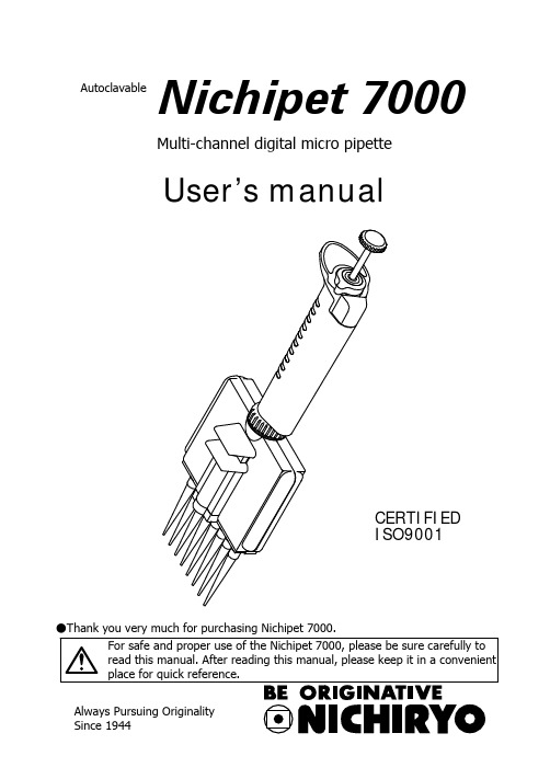
Nichipet 7000 说明书
●Thank you very much for purchasing Nichipet 7000.Multi-channel digital micro pipetteUser’s manualNichipet 7000AutoclavableCERTIFIED ISO9001Features● Complete autoclaving (121 °C 20 minutes) is possible with this unit. ● Fatigue free operation for long time.● Digital system allows easy one-touch volume setting. ● One-touch locking function with single hand.● Covering 0.5μL to 300μL range with 4 models each of 8 and 12 channels. ● Unit construction design helps to prevent accuracy change due to handtemperature.● Suitable for sampling to a micro plate with 96 well and 9 mm pitch.● Because the handle and casing angle can be adjusted freely (360 degrees), theunit can be used at a position of your choice.● Includes tip eject function. The tips can be removed without touching them byfingers.● The simple casing structure enables easy maintenance.Standard accessories● Tip 8 ch ......................... x 16 12 ch ........................ x 24 ● Silicone grease ................. x 1 ● Cleaning wire ................... x 1 ● Wrench ............................ x 1 ● User’s manual .................. x 1Please make sure that none of the above accessories are missing before using this unit.Multi-channel digital micro pipetteNichipet 7000AutoclavableC A U T I O N S t o d i s p o s e p i p e t t e s o r t i p s Please follow local low or ordinance when pipettes or tips are disposed.NOTEUsers are required to strictly observethe following points in order forthe instrument to keep its excellent precision,reproducibility and original performance for a long time.1. Do not expose pipette directly to the sun when working with it or for 2 hoursbefore starting work, otherwise the pipette may lose accuracy. Avoid working with pipettes in a humid and hot place.2. Just before starting work with pipette, avoid touching tip and nozzle cylinderas far as conditions are allowed. If nozzle cylinder is warmed by your hand, accuracy may vary.3. For pipetting, follow the forward method (the way explained in this manual). Ifit is performed in a different way, it may result in inaccurate pipetting.4. Operate push button very gently. If it is quickly released, it may result not onlyinaccurate pipetting but also deteriorated the pipette because sample liquid may be permeated into the main body.5. Do not reuse tip that has been used once, and carefully dispose used tip. If tipis used repeatedly, it may cause inaccurate and impure pipetting and cross contamination (*) among samples.* For example, if previous sample liquid is left inside tip, it is mixed with new sample liquid and the new sample is contaminated by the previous one.Therefore, pipetting of the next sample results wrong. This phenomenon is called mutual contamination of samples.6. Do not hold pipette horizontally or upside down when there is liquid inside tip,otherwise the liquid gets into the main body and the pipette may becontaminated.7. When autoclaving, do not pile pipettes on others in the autoclave or leanpipettes with a nozzle top facing down so that self-load is applied on thenozzle. This pipette is made of an autoclave compatible material, but because of high temperature in the sterilizer, there is a risk that parts subject to load will be deformed.8. After autoclaving and drying pipette, leave it until it gets completely coolbefore using again. If the pipette is used when warm, the accuracy may not come up to the standard level.9. After autoclaving and drying pipette, assemble the pipette after it is completelycooled, if it is assembled when it is still hot, it may cause deterioration in the pipette such as breakage of the screw threads.10. When rotating push button, do not exceed the specified sample volume limit,otherwise pipette may be damaged or deteriorated.11. Do not perform pipetting with less liquid than set volume. If the quantity ofliquid is less than the set volume, it may cause the liquid to scatter into the main body and the pipette may deteriorate in quality.ContentsOperating procedure (5)Disassembling/Reassembling the airtight chamber (9)Autoclaving/Drying the pipette (17)Specification (18)Calibration procedure (19)Troubleshooting (21)Parts list (23)Operation1. Volume setting1) Turn the lock handle to the unlock direction and loosen it. (Fig. A)2) Turn the push button to set the digital counter to the desired volume. Whenincreasing volume, first set the scale a half revolution further, and then set it to the desired amount. When decreasing the volume, the scale can be setdirectly to the desired amount. At this time set the counter’s scale to thepointer mark located at the bottom section of the counter window. (Fig. B)3) After volume setting, turn the lock handle in the lock direction and tighten.(Fig. A).Note: Do not exceed the specified liquid volume limit, otherwise the instrument may be damaged or deteriorate in the quality.Note: After changing the volume, use the unit after first carrying out a trial operation.2. Suction1) Attach the disposable tip to the nozzle (attach from the rack when doing so).2) Press the push button down to a ~ b. (Fig. C)3) With the push button pressed down, insert the top of the tip to a pointsuitable for suction of the desired volume. (Fig. D-1).4) Return the push button gently to its original position. The liquid will be pulledinto the tip. At this time pause for 1 second to wait for complete suction of the liquid. (Fig. D-2).5) Withdraw the tip gently from the liquid. By doing this gently, hardly any ofthe liquid will remain on the outside surface of the tip. If liquid does remain,remove it by paper or something similar, being careful not to touch the tip’spoint.Note: Do not carry out suction fromthe c position shown in Fig. C. (liquid will be pulled into the nozzle if done from this position)Note: Operate the push buttongently. Releasing quickly will cause liquid to be pulled into the inside of the unit causing possible loss of accuracy.3. Discharge1) Touch the top of the tip to the inside of the receiving vessel. (Fig. D-3). 2) Gently depress the push button from a to b. Wait about 1 second, then depress to the c position. The liquid is now discharged. (Fig. D-4,5). 3) Press the eject button to remove the used tip. (Fig. D-6).Do not touch the tip during use or after use when liquid that is harmful to the body is being used.Fig. Ca b cDisassembly and assembly of the airtight unitIf any of the problems included in the “Troubleshooting” section of this manual arise, use the following procedure to disassemble and inspect this unit.1. Disassembly1) Turn the ring in the direction of the arrow and remove the casing from the handle. (Fig. 1)Note: If the connection screw is loosened, tighten it with the providedwrench. (Fig. 2)2) Remove the screw that holds the ejector and remove the ejector from the casing. (Fig. 3)3) Remove the screw that holds the casing. (Fig. 4)4) Lightly press the nozzle and remove the casing A set as shown in Fig. 4. 5) Remove each part. (Fig. 5)2. Assembly1) Attach each part to casing B. (Fig. 5)2) Assemble and attach the casing A set. (Fig. 4)3) Assemble and attach the ejector to the assembled casing. (Fig. 3) 4) Assemble and attach the casing set to the handle. (Fig. 1)Note: When assembling be sure to set the counter to the maximumvolume range. (Parts will not mesh properly)Note: If the connection screw is loosened, tighten it with the providedwrench. (Fig. 2)Fig. 2Fig. 1HandleCasingRingWrenchHandleRingConnection washerConnection screwFig. 4Ejector buttonCasing AsetCasing holding screwFig. 3Ejector plateEjector plate holding screwEjector setFig.5N o z z l e s p r i n g h o l d e rN o z z l e s p r i n gP o s i t i o n t o g e a r p l u n g e a r sN o z z l eC a s i n g BF i r s t s p r i n gB u s hX r i n gX r i n g h o l d e rP l u n g e r s e tP l u n g e r h e a d s p r i n gP l u n g e r h o l d e r s e tAutoclavingAutoclaving of this complete unit is possible. Follow the procedure below at a temperature of 121° C for 20 minutes.1) Be sure to loosen the lock handle and set the counter to the maximumvolume number of the volume range.(Fig.A)2) Loosen a connecting screw in the Fig.2 by 180 degree.3) Loosen four screws on the casing in the Fig.4 by 180 degree.4) When placing inside the autoclaving unit, be careful not to damage thenozzle. Also, place in a position that does not put any weight on the nozzle.5) After autoclaving, be sure to dry the unit thoroughly.DryingCarry out drying immediately after autoclaving. Dry the unit thoroughly in a constant temperature air-drier at 60° C for over 60 minutes.1) Dry the product in the same condition as when it was autoclaved.2) Be careful not to damage the nozzle when placing the unit in the dryer. Alsomake sure that the unit is placed in a position that does not place any weight on the nozzle.3) Make sure that the unit turned to the normal temperature after the drying.Tighten the connecting screw in the Fig.2 and four screws on the casing in the Fig.4. And make sure that a ring in the Fig.1 is tightened.Note: After drying, if the unit is assembled while it is still warm, screw head damage etc., may occur causing damage to the product or loss of product performance. Be sure to reassemble the unit after it has completely cooled down. Also, using the product while it is warmmay result in loss of accuracy.Do not touch the unit directly with your hand just afterautoclaving and drying, because the unit is extremely hotduring autoclaving and drying. Directly touching the hot unitmay cause an accident.●Maximum Permissible ErrorsPipette types(Code) Volume range Measuredvolume(uL)Accuracy(%)Precision(%)1 ±8.0 ≤4.05 ±4.0 ≤2.0NP7-8V NP7-12V (0.5~10uL) 0.5-10(uL)10 ±2.0 ≤1.05 ±3.0 ≤1.525 ±2.0 ≤0.8NP7-8S NP7-12S (5~50uL) 5-50(uL)50 ±1.0 ≤0.540 ±1.4 ≤0.5100 ±1.0 ≤0.4NP7-8L NP7-12L (40~200uL) 40-200(uL)200 ±0.9 ≤0.350 ±1.4 ≤0.7150 ±1.0 ≤0.5NP7-8K NP7-12K (50~300uL) 50-300(uL)300 ±0.6 ≤0.2●Tips (autoclavable)Code Volume range(uL) Color Applicablemodel Tip length(mm)Q’tyBMT2-UT 0.1-10 Natural NP7-8V,12V 31.5 1000 BMT2-SG 5-200 Natural NP7-8S,12S、8L,12L 53.0 1000 BMT2-K 50-300 Natural NP7-8K,12K 58.9 1000●Rack tips (autoclavable)Code Volume range(uL) Color Applicablemodel Q’tyBMT2-UTR 0.1-10 Natural NP7-8V,12V 960(96x10cases) BMT2-SGR 5-200 Natural NP7-8S,12S、8L,12L 960(96 x 10cases)BMT2-KR 50-300 Natural NP7-8K,12K 960(96x10cases)RECALIBRATION PROCEDURE1. Remove the cap by pulling it out with your fingers. (Fig.6)2. Loosen the lock handle by turning it counter clockwise and stop when the ovalopening on the lock handle faces you. (Fig.7)3. Rotate the push button until one of two hex head screws can be seen throughthe oval opening. (Fig.7)4. Loosen both hex head screws with a hex head wrench (1.5 mm) by turningthem counterclockwise one by one. (Fig.8)5. Keeping the hex head wrench inserted into one hex head serew, turn the pushbutton to calibrate the pipette. (Fig.8)6. The pipetting volume can be adjusted by rotating the push button clockwise toincrease and counter-clockwise to decrease. Please refer to the table standardvolume adjustments.Angle 0.5-10uL 5-50uL 40-200uL 50-300uL 360゜ 0.31uL 1.6uL 6.5uL 9.6uL 720゜ 0.63uL 3.2uL 13uL 19.2uLafter adjusting the push button andmeasure the accuracy of the pipette.8. Repeat the above procedures untilthe pipette is calibrated within thespecified accuracy. An accuracy testshould be made at the specifiedminimum and maximum volume ofeach pipette.9. Return the cap to its original position.If the problem persists even after the above points have been checked, stop usage of the unit immediately and consult with the sales outlet where the unit was purchased.Caution: At this time please confirm that there has been nocontamination by chemicals that are harmful to the human body.TroubleshootingProblem Probable cause SolutionForeign matter in the nozzle.Remove foreign matter with provided cleaning wire.Liquid is not sucked in.X ring is worn or damaged.Replace the “X ring set” with the new set.Replace the “X ring set” and “Plunger set” with the new sets.Plunger is damaged or rusty.Liquid leakage from tip.Nozzle tip attachment part is damaged.Replace the “nozzle set” with the new set.Attached tips are loose.Attach the tips firmly .Plunger has shifted.Press the push button a few times.X ring is damaged.Replace the “X ring set” with the new set.Push button movement is poor.No grease on theplungers and/or X rings.Coat the plungers and/or X rings lightly with the provided grease.If immediately after suction or if there just some adherence of liquid,disassemble and clean the parts.Liquid in the nozzle.Ring is loose.Tighten the ringLooseness of body and casing.Connection screw is loose.Tighten the connection screw with the provided wrench.●Replacement parts list (Please specify volume and channel number when ordering)Spare parts Contents Size1 Common Ring xConnection washer x 1 CommonConnection screw x 1 CommonCasing A (x 1)Insert nut (x 5)Ejector button (x 1)Each sizeCasing A setEjector shaft A (x 1)Ejector shaft B (x 1)Ejector spring (x 1)Casing B x 1 Each sizePlunger fixing unit (x 1)First spring (x 2)Guide shaft (x 2)Guide tube (x 2)Each sizePlunger fixing unit setE ring (x 4)Bush (x 1)Stem (x 1)Plunger head spring set 8ch x 8, 12ch x 12 CommonPlunger (8ch x 8, 12ch x 12)Plunger setEach sizePlunger head (8ch x 8, 12ch x 12)X ring suppressor set X ring suppressor (8ch x 2, 12ch x 3) Each sizeNozzle spring holder set Nozzle spring holder (8ch x 2, 12ch x 3) CommonX ring set X ring (8ch x 8, 12ch x 12) Each sizeNozzle set Nozzle (8ch x 8, 12ch x 12) Each sizeNozzle spring set Nozzle spring (8ch x 8, 12ch x 12) CommonCasing holding screw x 4 CommonEjector plate (x 1)Each sizeEjector setEjector plate holding screw (x 1)1 Common Wrench xNote: Parts marked with a star (☆) influence precision of the product.When replacing these parts, please replace all of them with newparts.※Please contact your local distributor for price information.※ Specifications of the instruments and optional accessories as well ascontents of accessory sets are subject to change without notice.※ No part of this manual may be reproduced/reprinted in any form withoutpermission of the copyright holder. (This is strictly prohibited by thecopyright law.)Inspection and Calibration StatementThe enclosed pipette was tested and calibrated under closely controlled environmentalconditions to ensure that it meets published calibration specifications. The precision andaccuracy results obtained for this pipette are provided on the enclosed calibration certificate. Because temperature and humidity conditions affect the calibration results of liquidmeasurement devices, your pipette should be calibrated under conditions of use. Thecalibration results obtained in your laboratory may vary from our results due to differences inenvironmental testing conditions.Tokyo office1-10-1 Kandanishiki-cho, Chiyoda-ku, Tokyo 101-0054, JapanTEL: +81-3-6273-7652(English) FAX: +81-3-6273-7944URL: http://www.nichiryo.co.jp/。
PowerVerter APS700HF商品说明书

Coloque un fusible especificado a 125A a no más de 45.72 cm (18") de la batería en la línea positiva para proteger contra fuertes demandas de corriente que puedan ocurrir durante una falla del inversor.Inversor/cargador PowerVerter APS de 700W,12VCD y 120V con conmutación de transferencia automática y 1 tomacorrienteNÚMERO DE MODELO:APS700HFFuente de alimentación portátil de una sola salida para aplicaciones que demandan poca energía, como herramientas eléctricas y computadoras, como un inversor para vehículos, una fuente de alimentación de CA autónoma o UPS de operación extendida. Ideal para RV, vehículos de flota y camionetas van convertidas.GeneralEl inversor/cargador PowerVerter APS700HF de 700W, 12 CD y 120V CA es una fuente de alimentación fiable para una serie de aplicaciones con poca demanda de poca energía, desde herramientas eléctricas hasta computadoras y equipos de monitoreo delicados. Sin humos, combustible o ruido excesivo, es una alternativa excelente a un generador eléctrico.El inversor de CD a CA cuenta con un switch automático de línea a batería y un sistema de cargaintegrado que le permite trabajar como inversor en vehículo, fuente de alimentación de CA independiente o UPS de autonomía extendida Genera 700W de potencia continua, 1050W hasta 1.5 segundos, o1400W de potencia máxima hasta 1.1 segundos durante el arranque o ciclos de encendido/apagado del equipo. Un detector automático de sobrecarga, un ventilador de enfriamiento y un breaker de CA reprogramable protegen la unidad de daño.Diseñado para una instalación sencilla en vehículos recreativos, camiones para carretera, vehículos de flota y camionetas van convertidas, el APS700HF convierte la energía almacenada de una batería de 12V o una fuente de CD automotriz en alimentación de CA segura, estable y de grado computadora y la envía a un tomacorriente NEMA 5-15R para una autonomía extendida. Cuando es accionada por una fuente de CA externa de 120V, la unidad mantiene cargada la batería suministrada por el usuario a través de un sistema de carga de 6A de 3 etapas y, al mismo tiempo, envía alimentación de CA a los equipos conectados.Cuando se utiliza como un UPS, el APS700HF responde a apagones y caídas de voltaje con unatransferencia automática e instantánea a la salida de CA derivada de la batería. Los LED en la unidad indican los modos operativos CA / CD, sobrecarga, nivel de voltaje CD, apagado y fallas del sistemaCaracterísticasEnergía Confiable para Aplicaciones Móviles y Sitios RemotosGenera energía de 120V CA segura, estable de grado computadora desde en banco de batería de 12Vq Ideal para alimentar pequeñas aplicaciones que van desde herramientas eléctricas a computadoras y equipo delicado de monitoreo.qDestacadoGenera alimentación de CA de 120V limpia de una fuente de alimentación CA o CD qPotencia de salida de 700W continuos; potencia máxima de 1400WqOpción de conmutación de transferencia automática para operación del UPSqProtege contra apagones,sobretensiones, ruido en la línea EMI/RFIqGabinete compacto de aluminio ligero que pesa solo 1.8 Kg (4libras)qEl Paquete IncluyeInversor/cargador APSPowerVerter APS700HF de 12V CD y 120V CA de 700W qManual del propietarioqDiseñado para una fácil instalación en vehículos recreativos, camiones para carretera, vehículos deqflota y furgonetas convertidasFunciona como un inversor para vehículos, una fuente de alimentación de CA independiente o unaqUPS de operación extendida.Cuenta con tomacorriente NEMA 5-15RqAutonomía ilimitada con una variedad de baterías suministradas por el usuarioqCumple con las demandas de energía normal y máxima700W de potencia continuaq1050W de potencia de reserva hasta 1.5 segundos.q1400W de potencia máxima por hasta 1.1 segundos para aceptar demandas máximas duranteqarranque y ciclos de encendido/apagado del equipoUn detector automático de sobrecarga, ventilador de enfriamiento de varias velocidad incorporado yqbreakers de CA restaurables protegen la unidad contra dañosJuego de terminales de entrada CD de alta corriente para una instalación simple de cableadoqpermanenteConmutación de transferencia automáticaTransfiere los interruptores de relés a la energía del inversor durante los apagones en 16.6 msqEl switch de 3 posiciones permite los modos Automático, Solo Carga o Apagado del SistemaqCargador de Batería de 3 EtapasFunciona como cargador de baterías cuando se suministra energía de CA externa de 120V CA yqalimenta a los equipos conectadosProtege a la batería de las sobrecargas y sobredescargasqLa protección de batería baja evita el agotamiento excesivo de la bateríaqLEDs del panel frontalIndican los modos operativos CA/CD, estado de sobrecarga, nivel de voltaje CD, estado de apagado y qestado de fallas al sistemaGabinete Compacto de AluminioPesa solo 1.8 kg [4 lb]qResiste humedad y ambientes con un alto nivel de humedadqPatas de instalación incorporadas para su instalación en cualquier superficie horizontal rígidaqUna terminal de conexión a tierra conecta la unidad a tierra o al sistema de descarga a tierra delqvehículoEl cable de alimentación CA incorporado y clavija NEMA 5-15P se conecta a la fuente de alimentación qde CAEspecificacionesPeriodo de garantía del producto(México)Garantía limitada por 2 añosPeriodo de garantía del producto(Puerto Rico)Garantía limitada por 1 año© 2023 Eaton. All Rights Reserved.Eaton is a registered trademark. All other trademarksare the property of their respective owners.。
气体检测仪700系列说明书

DescriptionModel 700 Series Sensors are a non-intrusive “Smart” sensors designed to detect and monitor oxygen and Toxic Gases in air using electrochemical sensor technology.The intelligent plug-in, field replaceable cell provides automatic recognition of gas type and range, and features over-sized gold-plated connections that help prevent corrosion.The Model 700’s rugged framework includes an intrinsically safe electro-polished 316 stainless steel housing with fully encapsulated electronics and dual layer surge protection.This innovative design virtually eliminates sensor failure due to water in-gress, corrosion, vibration, and transient spikes.A primary feature of the Model 700 is embedded intuitive software that simplifies operator interface by guiding the user through routinecalibration, configuration, and fault diagnostic functions using a built-in alpha/numeric display.The Model 700 is equipped with standard analog 4-20mA, and Modbus™ RS-485 outputs. Among its unique features is a wireless option that can be used with Detcon’s SmartWireless® product line. Additional integration options include a Remote Alarm Module (RAM) and HART.Detcon’s toxic gas and oxygen sensors have a long shelf life and are sup-ported by an industry-leading warranty.Model DM 700Toxic gas sensorsFeaturesFailsafe User-Friendly Interface• LED Display (With Antiglare Cover)• Full Text Display Method • Non-intrusive Interface • Auto Zero/Auto Span• Pre-emptive Fault DiagnosticsEnvironmentally Bulletproof• Electropolished 316SS Construction • 100% Epoxy Encapsulated Circuitry • Bulletproof I/O Protection• Water-proof, Corrosion-Proof, Vibration-ProofModular and Serviceable • Modular Design• Plug and Play Components• Quick Thread Release Sensor Endcap (Allen Wrench only required)• Integral Calibration PortApplications• Oil & Gas• Chemical Plants • Food & Beverage • Steel Mills • Pulp and Paper • Refineries• Wastewater Treatment Plants •Utilities(shown as PN 967-505094-100 in SS junction box)Gas Part Number Warranty Measuring Accuracy Response Time Operating Temp Storage Temp Operating Humidity Acetylene (*See Note)967-12EG91-100 2 years0-100 ppm±2% FS T90≤140 seconds-4 to 122ºF/-20 to 50ºC-31 to 131ºF/-35 to 55ºC15-90% RH non-condensing Ammonia967-505091-100 2 years0-100 ppm±2% FS T90≤90 seconds-40 to 122ºF/-40 to 50ºC-31 to 131ºF/-35 to 55ºC15-90% RH non-condensing Arsine967-191991-001 1.5 years0-1 ppm±2% FS T90≤60 seconds-4 to 104ºF/-20 to 40ºC-31 to 131ºF/-35 to 55ºC20-95% RH non-condensing Bromine967-747591-005 2 years0-5 ppm±2% FS T90≤60 seconds-4 to 122ºF/-20 to 50ºC-31 to 131ºF/-35 to 55ºC15-95% RH non-condensing Butadiene967-12EB91-100 2 years0-100 ppm±2% FS T90≤140 seconds-4 to 122ºF/-20 to 50ºC-31 to 131ºF/-35 to 55ºC15-90% RH non-condensingCarbon Monoxide967-444491-100 3 years0-100 ppm±2% FS T50≤10 sec./T90≤30 sec.-40 to 122ºF/-40 to 50ºC-31 to 131ºF/-35 to 55ºC15-90% RH non-condensingChlorine967-747491-010 2 years0-10 ppm±2% FS T90≤60 seconds-4 to 122ºF/-20 to 50ºC-31 to 131ºF/-35 to 55ºC15-90% RH non-condensing Chlorine Dioxide 700967-747691-050 2 years0-50 ppm±2% FS T90≤120 seconds-4 to 104ºF/-20 to 40ºC-31 to 131ºF/-35 to 55ºC10-95% RH non-condensing Chlorine Dioxide 701967-777791-001 2 years0-1 ppm±2% FS T90≤60 seconds-4 to 104ºF/-20 to 40ºC-31 to 131ºF/-35 to 55ºC15-90% RH non-condensing Diborane967-192191-005 1.5 years0-5 ppm±2% FS T90≤60 seconds-4 to 104ºF/-20 to 40ºC-31 to 131ºF/-35 to 55ºC20-95% RH non-condensing Ethanol967-12EO91-100 2 years0-100 ppm±2% FS T90≤140 seconds-4 to 122ºF/-20 to 50ºC-31 to 131ºF/-35 to 55ºC15-90% RH non-condensing Ethylene (*See Note 2)967-12ED91-100 2 years0-100 ppm±2% FS T90≤140 seconds-4 to 122ºF/-20 to 50ºC-31 to 131ºF/-35 to 55ºC15-90% RH non-condensing Ethylene Oxide967-12EJ91-100 2 years0-100 ppm±2% FS T90≤140 seconds-4 to 122ºF/-20 to 50ºC-31 to 131ºF/-35 to 55ºC15-90% RH non-condensing Fluorine967-272791-001 1.5 years0-1 ppm±2% FS T90≤80 seconds14 to 104ºF/-10 to 40ºC-31 to 131ºF/-35 to 55ºC10-95% RH non-condensing Formaldehyde967-12EP91-100 2 years0-100 ppm±2% FS T90≤140 seconds-4 to 122ºF/-20 to 50ºC-31 to 131ºF/-35 to 55ºC15-90% RH non-condensing Germane967-232591-002 1.5 years0-2 ppm±2% FS T90≤60 seconds-4 to 104ºF/-20 to 40ºC-31 to 131ºF/-35 to 55ºC20-95% RH non-condensing Hydrogen (1%)967-070791-01P 2 years0-1%volume±2% FS T90≤60 seconds-40 to 104ºF/-40 to 40ºC-31 to 131ºF/-35 to 55ºC5-90% RH non-condensing Hydrogen (4%)967-050591-04P 2 years0-4%±2% FS T90≤60 seconds-40 to 104ºF/-40 to 40ºC-31 to 131ºF/-35 to 55ºC5-95% RH non-condensing Hydrogen PPM967-848491-100 2 years0-100 ppm±2% FS T90≤30 seconds-4 to 122ºF/-20 to 50ºC-31 to 131ºF/-35 to 55ºC15-90% RH non-condensing Hydrogen Bromide967-090891-030 1.5 years0-30 ppm±2% FS T90≤70 seconds-4 to 104ºF/-20 to 40ºC-31 to 131ºF/-35 to 55ºC10-95% RH non-condensing Hydrogen Chloride967-090991-030 1.5 years0-30 ppm±2% FS T90≤70 seconds-4 to 104ºF/-20 to 40ºC-31 to 131ºF/-35 to 55ºC10-95% RH non-condensing Hydrogen Cyanide967-131391-030 2 years0-30 ppm±2% FS T90≤40 seconds-40 to 104ºF/-40 to 40ºC-31 to 131ºF/-35 to 55ºC5-95% RH non-condensing Hydrogen Fluoride967-333391-010 1.5 years0-10 ppm±2% FS T90≤90 seconds-4 to 95ºF/-20 to 35ºC-31 to 131ºF/-35 to 55ºC10-80% RH non-condensingHydrogen Sulfide967-242491-100 2 years0-100 ppm±2% FS T50≤10 sec./T80≤30 sec.-40 to 122ºF/-40 to 50ºC-31 to 131ºF/-35 to 55ºC5-90% RH non-condensingHydrogen Sulfide (DC)*967-303091-1002 years0-100 ppm±10%applied gasconcentrationor ±3 ppm,whichever isgreaterT20 ≤ 20sec-40 to +131°F/-40 to +55°C -31 to +131°F/-35 to +55°C5-90% RH non-condensing 967-303091-050T50 ≤ 45 sec967-303091-025 T90 ≤ 60 secMethanol967-12EE91-100 2 years0-100 ppm±2% FS T90≤140 seconds-4 to 122ºF/-20 to 50ºC-31 to +131ºF/-35 to 55ºC15-90% RH non-condensing Methyl Mercaptan967-12EK91-100 2 years0-100 ppm±2% FS T90≤45 seconds-40 to 122ºF/-40 to 50ºC-31 to +131ºF/-35 to 55ºC15-90% RH non-condensing Nitric Oxide967-949491-100 3 years0-100 ppm±2% FS T90≤10 seconds-4 to 122ºF/-20 to 50ºC-31 to +131ºF/-35 to 55ºC15-90% RH non-condensing Nitrogen Dioxide967-646491-010 2 years0-10 ppm±2% FS T90≤40 seconds-4 to 122ºF/-20 to 50ºC-31 to +131ºF/-35 to 55ºC15-90% RH non-condensingOxygen967-341520-025 2 years 0-25%volume±1% FS T90≤10 seconds-4 to 122ºF/-20 to 50ºC-40 to 122ºF/ -40 to 50ºC15-90% RH non-condensingOzone967-393991-001 2 years0-1 ppm±2% FS T90≤120 seconds14 to 104ºF/-10 to 40ºC-31 to +131ºF/ -35 to 55ºC10-95% RH non-condensing Phosphine967-192091-005 1.5 years0-5 ppm±2% FS T90≤30 seconds-4 to 104ºF/-20 to 40ºC-31 to +131ºF/ -35 to +55ºC20-95% RH non-condensing Silane967-232391-050 1.5 years0-50 ppm±2% FS T90≤60 seconds-4 to 104ºF/-20 to 40ºC-31 to 131ºF/ -35 to +55ºC20-95% RH non-condensing Sulfur Dioxide967-555591-020 2 years0-20 ppm±2% FS T90≤20 seconds-4 to 122ºF/-20 to 50ºC-31 to +131ºF/ -35 to +55ºC15-90% RH non-condensing *Note: Acetylene can only be used with a Group A enclosure.*Note2: This product is a safety device to detect hazardous conditions, and is not intended for process control application in fruit ripening operations.*Note3: DC=Desert Climate Sensors are 3rd-party test report to ISA 92.00.01 2010 standardSystem specifications Sensor TypeContinuous diffusion/adsorption3-electrode electrochemical cellPlug-in field replaceable Intelligent Type OutputsLinear 4-20 mA DCRS-485 MODBUS-RTUElectrical ClassificationExplosion proofC CSAUSClass I, Division 1, Groups B, C, D ()Class I, Zone 1, Group IICATEXII 2 G Ex d ib IIB + H2 T4 GBIngress ProtectionNEMA 4X, IP66Safety ApprovalscCSAusATEXCE MarkingSIL2 Certified to IEC 61508* Specifications subject to change without noticeOrder guidePN 967 - _ _ _ 090 - _ _ z DM - 700 Sensor Assembly (no junction box) PN 967 - _ _ _ 091 - _ _ z DM - 700 Sensor Assembly with Aluminum J-Box PN 967 - _ _ _ 094 - _ _ z DM - 700 Sensor Assembly with 316 SS J-Box _ = Any character as shown in table on prior pagez = Code for Regulatory Approval Required, C for CSA or A for ATEX, others available.C for CSA or A for ATEX Mechanical specificationsDimensions7”H x 2.2” Dia.; 178mmH x 65mm Dia. (sensor assembly only)11”H x 6.1”W x 3.75”D; 280mmH x 155mmW x 96mmD (with junction box) Mounting holes (J-box) 5.5”; 140mm center to centerWeight2 lbs; 0.907kg (sensor only)6 lbs; 2.72kg (w/aluminum j-box)9 lbs; 4.08kg (w/stainless steel j-box)Electrical specificationsPower Input11 - 30 VDCPower ConsumptionNormal operation = 30mA @ 24V (<0.75 watt)Maximum = 50mA @ 24V (1.2 watts)Inrush Current500mA @ 24V (typical)RFI/EMI ProtectionComplies with EN50270Analog OutputLinear 4-20mA DC (1,000 ohms max loop load @ 24VDC)0mA All Fault Diagnostics2mA In-Calibration4-20mA 0-100% full-scale22mA Over-range conditionSerial RS-485 OutputRS-485 Modbus™ RTUBaud Rate9600 BPS (9600, N, 8, 1 Half Duplex)Status Indicators4-digit LED display with gas concentrationFull-script menu prompts for AutoSpan,Set-up Options, and Fault ReportingFaults MonitoredLoop, Input Voltage,Missing Sensor, Zero,Processor, Memory, CalibrationCable RequirementsPower/Analog3-wire shielded cableMaximum distance is 13,300 feet with 14 AWGSerial Output2-wire twisted-pair with ground, shielded communicationcable specifically for use with RS-485 installationsMaximum distance is 4,000 feet to last sensorI/O ProtectionOver -voltage, Miswiring, EMI/RFI ImmunityIntegration optionsThe first three characters of the PN define the Integration options as follows:PN 9R7 - Remote Alarm Module (Remote Operation and 2 Alarm Relays plus Fault)PN 9H7- Hart Integration Module (Hart Communication Protocol version 7.0, HART Registered)PN 9K7- Combination HART / Remote Alarm Module (Combines the features of both into one module)Copyright © 2020 Teledyne Technologies. All rights reserved. **********************************************AMERICAS4055 Technology Forest Blvd.The Woodlands, TX 77381USATel.: +1 713-559-9200Fax: +1 713-893-6729EMEAZI Est, Rue Orfila,CS 2041762027 ARRAS CEDEX, France Tel.: +33-3-21-60-80-80Fax: +33-3-21-60-80-00ASIA PACIFIC290 Guiqiao RoadPudong, Shanghai 201206People's Republic of China Tel.: +86-21-3127-6373Fax: +86-21-3127-6365Teledyne Gas & Flame Detection quality assurance programmes demand the continuous assessment and improvement of all our products. Information in this leaflet could thus change without notification and does not constitute a product specification. For more informa-tion, please contact us or your company representative。
- 1、下载文档前请自行甄别文档内容的完整性,平台不提供额外的编辑、内容补充、找答案等附加服务。
- 2、"仅部分预览"的文档,不可在线预览部分如存在完整性等问题,可反馈申请退款(可完整预览的文档不适用该条件!)。
- 3、如文档侵犯您的权益,请联系客服反馈,我们会尽快为您处理(人工客服工作时间:9:00-18:30)。
apit700说明书
长度:1445mm(机身,头罩头到垂直尾翼尾)
宽度:187mm(脚架)
高度:331mm(脚架到旋翼头)
主旋翼直径:1558mm
RTF 重量(不含油):4000g
主桨:标配 690mm(范围:650-730mm)
尾桨:标配 105mm(范围:105-115mm)
发动机:90-105级
倾斜盘舵机:标准 40mm
锁尾舵机:标准 40mm
油门舵机:中型 35mm 或标准 40mm
主旋翼减速比:标配 8:1
尾旋翼减速比:标配 5.1:1
油箱容量:650ml(650cc)
建议接收电池:2S 1800-2500毫安
设计亮点:
RAW NITRO 极 700 油动直升机作为 SAB RAW 极系列,当然与电动版的 RAW 700 共享了许多的 DNA 设计元素。
各位可以从下图的主结构设计看出很多共同点:
SAB RAW NITRO 极 700 油动直升机主结构设计:
整体设计还是依然的非常紧凑。
旋翼设计与主齿轮箱的设计理念
是相同的。
也共用部分的主要配件和模块。
但是电动和油动并不是很纯粹的就将设计改一下,找个位置将发动机固定好就好。
例如传动的比例,重量在飞行前、中、后期的变化,重心本身是否能更优化,飞行期间的重心变化(是的,油动直升机的重量和重心在飞行过程中是会改变的)等等都要考虑进去。
所以,很多设计是表面看不见的。
SAB 这次在为这台油机的整体设计上,的确下了很多功夫,可以看得出来做了很多新的尝试和测试。
这些工作的目的也是希望让这台全新的 RAW NITRO 极 700 油动直升机成为更轻、更好飞、更维修便利,更为完美的一台油动直升机。
油箱设计
新的 RAW NITRO 极 700 油动直升机油箱容量是 650ml(650cc)。
容量很大,与之前的 BN 和 BNS 的油箱容量相同。
这样的容量,过
去也曾经有过少则 7-8分钟,多则 10多分钟的飞行时间。
SAB RAW NITRO 极 700 油动直升机 650ML 油箱。
油箱安装的位置是非常重要的。
RAW NITRO 极 700 油动直升机
油箱位置是在主轴正下方。
SAB RAW NITRO 极 700 油动直升机油箱位置
这样的设计能尽可能减少重心在飞行过程中的变化,降低燃油(液态)在不同姿态(正飞,倒立,翻滚时等)流动和晃动所产生的惯性。
SAB RAW NITRO 极 700 油动直升机前方。
从侧面看完,那我们再从前面看一下。
各位有没有看出什么不寻
常的地方?如果没有就对了。
注意设计美学的 SAB 也让油箱藏在了机身内部,与机身几乎同宽的。
所以从前面看,你是看不出左右突出的油箱,也让整体更美观流线。
这也降低了液体左右摇晃的问题,使重心更集中于机身中央。
接收电池与电子设备的安置
油动直升机与电动直升机有一个很大的不同就是油动直升机仍
然需要使用一个接收电池为诸多的电子控制设备供电。
一天的飞行可能要两到三个,看起落次数。
油动直升机也会安装小型的 BEC,油动专用定速器,点火器等设备。
这些设备除了增加绝对的重量之外,对前后重心有很大的影响。
同时,设备的种类和数量在越来越紧凑的机身设计下,也为安装空间与布线带来许多问题。
在全新的 RAW NITRO 极 700 油动直升机上,SAB 做了一个大胆的新尝试。
就是将接收电池也和油箱一样,移到了机身中央的位置。
SAB RAW NITRO 极 700 油动直升机接收电池盒
这也是很多朋友在看到官方发布的图片后,一直在问这个神秘的盒子是什么。
答案就是:接收电池的盒子。
以下就是说明书中关于这个电池盒的安装细节:
SAB RAW NITRO 极 700 油动直升机接收电池安装说明
有人会问,那接收电池不是原先都放前面。
是的。
但就是因为重心平衡的原因,SAB 这次改放在侧面。
接收电池放中间有助于重心平衡。
以前接收电池都是放在前面,但是每个人使用的 2S 接收电池容量和重量不同,有重有轻。
直升机每次换完电池就要重新检查平衡。
玩家们就需要电池贴上贴下,中间装头罩,晃一晃直升机,找到最佳的点。
另外,油机又有满油和空油的前后平衡问题。
所以 SAB 将接收电池改放这里,在主轴位置,刚好在中间,解决问题。
SAB RAW NITRO 极 700 油动直升机前端设备座与风扇罩。
另外,我们刚刚提到拆头罩。
SAB RAW 系列的主张就是能不拆头罩,就不拆头罩。
所以接收电池放侧面,不用拆头罩更换电池。
前方设备座也就可以放不常拆卸的电子设备,例如定速、BEC 或二合一BEC。
这些设备不用跟接收电池挤在一起。
这样也腾出更多空间,布线也更干净、整齐。
发动机散热与传动加固:
RAW NITRO 极 700 油动直升机的建议发动机规格是 .90 - .105级。
与电动 RAW 700 一样,机身是采镂空设计的。
这样的设计也因发动机安装的位置周围都是镂空的,更有助于发动机散热。