DS 系列防雷器说明书
流水线防雷设备值iances说明书

OverviewPwrESD is an integrated electro-hydraulic power unit designed to operate hydraulic actuators for surface safety valves (SSVs) and flow-line ESD valves.The compact system design offers minimum added footprint to the SSV while offering both local and remote opening and closing functions to the valve. PwrESD also minimizes the number of hydraulic fittings and connections to limit potential leakage points.The system is offered with either 24 VDC or AC powered motor with 1/4 to 1 horsepower (0.18 to 0.75 kW) for remote opening and maintaining a fully open position. It also includes a backup hydraulic hand pump. A 24 VDC low power (0.85 watts) solenoid valve is used to retain the pressure in a low-pressure circuit to control the opening and closing operation of the SSV. The system can integrate pressure transmitters, limit switches, position transmitter, and a hydraulic fluid level switch into an explosion proof electrical enclosure ready for wiring to Stream-Flo’s Intelligent Valve Controller (IVC), Distributed Control System (DCS), or Programmable Logic Controller (PLC).Features and Benefits:•Compact design – the system is designed to be totally self-contained for ease of installation to new or existing SSVs. •Local and remote operation.•Capable of independent emergency shutdown (ESD) initiated through a solenoid valve, manual trip (ESD) valve, and/or fusible element, or other means.•Multiple power options for the electric motor with CSA/UL and/or ATEX/IECEx certifications.•Multiple displacement options for the motor-driven hydraulic pump for different valve opening speedrequirements.•Operating hydraulic pressure up to 3,300 psi (22,753 kPa).Stream-Flo PwrESD mounted to Hydraulic ActuatorSpecificationsBasic Electro-Hydraulic Power UnitElectric MotorVoltage 115/230 VAC 1PH, 208-230/460 VAC 3PH, or 24 VDCPower Power options: ¼ to 1 HP (0.18 to 0.75 kW)Rotational Speed 1750 rpm (CSA/UL) or 1450 rpm (ATEX/IEC Ex)Operating Temperature Range CSA/UL -40°F to +104°F (-40°C to +40°C)ATEX/IEC Ex -4°F to +140°F (-20°C to +60°C)Hazardous Area Approvals CSA/UL Class 1 Division 1, Groups C, DATEX/IEC Ex db IIB T4 GbPumpsMotor-Operated Pump Micro gear pumpDisplacement: 0.012 to 0.076 in3/rev (0.1 to 1.5 cm3/rev)Flow rate: 0.07 to 0.54 gpm (0.26 to 2.04 l/min)Manual Pump Plunger pumpDisplacement: 0.66 to 1.18 in3/stroke(10.8 to 19.3 cm3/stroke)ReservoirFeatures Integrates to HP manifold, easily disassembled for maintenance, and accessible level switchport.Sizes 150 in3 (2.5 liters)300 in3 (4.9 liters)Hydraulic Fluid Industrial hydraulic fluid for use to below -40 °F (-40 °C) ambient low temperature Solenoid ValvePower Consumption 0.85 watts (3 watts in-rush)Input Voltage 24 VDCOperating Temperature Range -76°F to +122°F (-60°C to +50°C)Number of ports 3/2Flow Coefficient (Cv) 0.6Operating Pressure 0 to 174 psi (0 to 1,200 kPa)Hazardous Area Approvals CSA/UL Class 1 Division 1, Groups B, C, DATEX/IEC Ex d IICHydraulicsMaximum Operating Pressure 3,300 psi (22,753 kPa)System Temperature rating -40 °F to 180 °F (-40°C to +82°C) limited by gear pumpPressure Reducing Valve (PRV) Flow Coefficient (Cv): 0.43Low-Pressure Safety/Relief Valve Flow Coefficient (Cv): 6.10Set Pressure: 150 psi (1,034 kPa)High-Pressure Safety/Relief Valve Flow Coefficient (Cv): 0.24Set Pressure up to: 2,500 psi (17,237 kPa) and 4,000 psi (27,580 kPa)Trip/Reset Control (1) Manual Emergency Shutdown Valve (ESDV), or(2) Manual Override Valve (MOV)Optional ItemsQuick Exhaust ValveMaximum Working Pressure6,000 psi (41,369 kPa) Flow Control ApplicationNormally OpenControl Function 3-way – poppet assembly operated Flow Coefficient (Cv)4.33Junction BoxFeaturesMotor contactor, terminal blocks, ground bar, RTD converter, and drain breather Temperature SensorRTD probeOperating Temperature Range-40°F to +176°F (-40°C to +80°C)Hazardous Area ApprovalsCSA/UL Class 1 Division 1, Groups A, B, C, D ATEX/IEC Ex d IIB+H2Level SwitchMeasurement Type Non-contact (Magnetic) Contact ArrangementSPDT (Form C)Operating Temperature Range-40°F to +212°F (-40°C to +100°C)Hazardous Area ApprovalsCSA/UL Class 1 Division 1, Groups A, B, C, D ATEX/IEC Ex db/tbPressure TransmittersInput voltage10-30 VDC Output4-20 mAOperating temperature rangeMedium: -40°F to +212°F (-40°C to +100°C)Ambient: -40°F to +221°F (-40°C to +105°C) Hydraulic low-pressure range 0 to 200 psi (0 to 1,379 kPa) Hydraulic high-pressure range0 to 5,000 psi (0 to 34,474 kPa) Line pressure range 0 to 15,000 psi (0 to 103,421 kPa)Hazardous area approvalsCSA/FM Class 1 Division 1, Groups A, B, C, D ATEX/IEC Ex d IIC T6…T1 GbPosition TransmitterMeasurement TypeNon-contact (Hall-effect)Input Voltage10-30 VDC Output4-20 mAOperating temperature range-40°F to +185°F (-40°C to +85°C)Hazardous area approvalsCSA/FM Class 1 Division 1, Groups B, C, D ATEX/IEC Ex d IIB+H2Limit SwitchesMeasurement Type Non-contact (Magnetic)Contact Arrangement/Material SPDT (Form C) TungstenOperating temperature range CSA/UL -40°F to +221°F (-40°C to +105°C)ATEX/IEC Ex -4°F to +158°F (-20°C to +70°C)Hazardous area approvals CSA/UL Class 1 Division 1, Groups A, B, C, DATEX/IEC Ex d IICOther Optional Items• High-pressure accumulator • Pressure switches• Pressure gauges•Motor disconnect switchHydraulic CircuitThe PwrESD hydraulic circuit is composed of 2 loops: low-pressure (LP) and high-pressure (HP). The LP circuit is enclosed within the Pressure Reducing Valve - PRV (3) and ESD Valve (4) and connects to a solenoid valve (6). The HP circuit spans between the Power Unit (1), Manual Pump (2), and PRV (3) and connects to the valve actuator or the Surface Safety Valve (SSV).The circuit has two safety/relief valves (PSVs). The first is HP-PSV (1E), located in the Power Unit assembly (1) to relieve pressure in the HP circuit. The second is LP-PSV (3B), located in the PRV assembly (3), to relieve pressure in the LP circuit.Item Description Item Description1 Power Unit 4 ESD Valve Assembly1A Electric Motor 4A ESD Valve1B Gear Pump 4B Fusible Element1C Suction Filter 5 Hydraulic Reservoir1D Discharge Check Valve 5A Filler/Breather Cap1E HP Pressure Safety/Relief Valve 5B Sight Glass2 Manual Pump 5C Fluid Level Switch2A Suction Filter 6 Solenoid Valve2B Suction Check Valve 7 Pressure Transmitter, Hydraulic High Pressure2C Discharge Check Valve 8 Pressure Transmitter, Hydraulic Low Pressure3 Pressure Reducing Valve Assembly 9 Pressure Transmitter, Upstream Line Pressure3A Pressure Reducing Valve 10 Pressure Transmitter, Downstream Line Pressure3B Low Pressure Safety/Relief Valve 11 Valve Position Transmitter / Limit Switches3C Low Pressure AccumulatorHydraulic circuit of the PwrESD system with recommended instrumentationPump and Motor Power SelectionBasic Electro-Hydraulic Power Unit Major DimensionsModel Number SelectionExample Model Number:PwrESD 1-2-1-2000-28-ACU-LS-PTHP-PTLP-ST-JB-DS •Motor Certification = CSA/UL•Pump Displacement = 0.016 in3/rev•Motor Voltage = 24 VDC•MWP = 2000 psi•Swept Volume = 28 in3•Accumulator•Hydraulic Level Switch•Hydraulic High Pressure Transmitter•Hydraulic Low Pressure Transmitter•Position Transmitter•Junction Box•Motor Disconnect Switch。
避雷器说明书
避雷器说明书中文名:避雷器外文名:Surgearrester材质:氧化锌作用:释放过电压能量1)用于保护电气设备免受高瞬态过电压危害并限制续流时间也常限制续流幅值的一种电器。
本术语包含运行安装时对于该电器正常功能所必须的任何外部间隙,而不论其是否作为整体的一个部件。
注1:避雷器通常连接在电网导线与地线之间,然而有时也连接在电器绕组旁或导线之间。
注2:避雷器有时也称为过电压保护器,过电压限制器(surgedivider)。
2)避雷器是通信线缆防止雷电损坏时经常采用的另一种重要的设备。
一、避雷器定义避雷器:用于保护电气设备免受雷击时高瞬态过电压危害,并限制续流时间,也常限制续流幅值的一种电器。
避雷器有时也称为过电压保护器,过电压限制器。
中文名:避雷器外文名:Arrester别称:无应用学科:信息通信特点:高瞬态、过电压、电器、雷电防护二、避雷器适用范围交流无间隙金属氧化物避雷器用于保护交流输变电设备的绝缘,免受雷电过电压和操作过电压损害。
适用于变压器、输电线路、配电屏、开关柜、电力计量箱、真空开关、并联补偿电容器、旋转电机及半导体器件等过电压保护。
三、避雷器特点与原理交流无间隙金属氧化物避雷器具有优异的非线性伏·安特性,响应特性好、无续流、通流容量大、残压低、抑制过电压能力强、耐污秽、抗老化、不受海拔约束、结构简单、无间隙、密封严、寿命长等特点。
避雷器在正常系统工作电压下,呈现高电阻状态,仅有微安级电流通过。
在过电压大电流作用下它便呈现低电阻,从而限制了避雷器两端的残压四、避雷器分类避雷器分为很多种,有金属氧化物避雷器,线路型金属氧化物避雷器,无间隙线路型金属氧化物避雷器,全绝缘复合外套金属氧化物避雷器,可卸式避雷器。
避雷器的主要类型有管型避雷器、阀型避雷器和氧化锌避雷器等。
每种类型避雷器的主要工作原理是不同的,但是它们的工作实质是相同的,都是为了保护通信线缆和通信设备不受损害。
4.1、管型避雷器管型避雷器实际是一种具有较高熄弧能力的保护间隙,它由两个串联间隙组成,一个间隙在大气中,称为外间隙,它的任务就是隔离工作电压,避免产气管被流经管子的工频泄露电流所烧坏;另一个装设在气管内,称为内间隙或者灭弧间隙,管型避雷器的灭弧能力与工频续流的大小有关。
避雷器参数说明
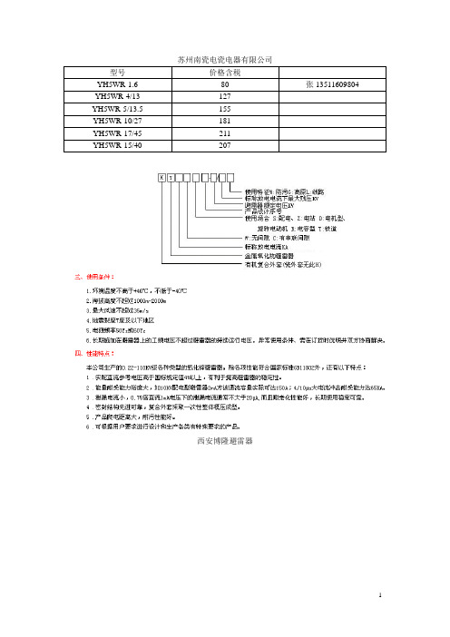
苏州南瓷电瓷电器有限公司型号价格含税YH5WR-1.6 80 张135****9804 YH5WR-4/13 127YH5WR-5/13.5 155YH5WR-10/27 181YH5WR-17/45 211YH5WR-15/40 207西安博隆避雷器类别避雷器型号避雷器额定电压(kV)系统标称电压(kV)持续运行电压(kV)直流1mA参考电压(不小于)(kV)0.75倍直流参考电压下漏流(不大于)(μA)陡坡冲击电流(不大于)(kV)雷电冲击电流(不大于)(kV)操作冲击残压(不大于)(kV)2mS方波通流容量(电流A、18次)并联补偿电容器(R)H(Y)5WR-8/13.5 5 3 4.0 7.2 40-13.5 10.5 400 6565-100 H(Y)5WR-10/27 10 6 8.0 14.4 40 27.0 21.0 400H(Y)5WR-17/44 17 10 13.6 24.0 50 46.0 35.0 400-1200H(Y)5WR-48/134(130,125) 48 35 38.1 73.0 50- 134(130,125)105 400-1200 65-100 H(Y)5WR-51/134(130,125) 51 35 40.8 73.0 50 105 400-1200 65-100H(Y)5WR-52.7/134(130,125) 52.7 35 42.2 73.0 50 105 400-1200 65-100 H(Y)5WR-54/134(130,125) 54 35 43.2 73.0 50 105 400-1200 65-100配电型无间隙金属氧化物避雷器电站型无间隙金属氧化物避雷器并联补偿电容器用无间隙金属氧化物避雷器电机型无间隙金属氧化物避雷器变压器中性点用无间隙金属氧化物避雷器带串联间隙金属氧化物避雷器电气化铁道保护用无间隙金属氧化物避雷器FCD3 系列阀式磁吹防爆避雷器低压避雷器一、概述金属氧化物避雷器是当前限制过电压最先进的一种保护电器,被广泛地用于发电、输变电、配电系统中,保护缘免受过电压的损害。
二合一和三合一说明书(2-1)

室内多功能防雷器说明书
一、功能与特点
多功能防雷器是为监控系统量身定做的专业一体化多功能电涌保护器(二合一、三合一防雷器)。
可以分别对摄像机的电源、视频、云台控制线路实施浪涌和防静电保护,最高放电电流可达10KA。
反应速度为纳秒级,可充分保护高端、昂贵的监控设备。
特点
该产品多级保护电路设计,核心元器件采用德国西门子产品;残压低、反应灵敏、通流量大;安装方便、维护简单等特点。
三、
1、防雷器串联在信号通道和被保护设备之间。
2、防雷器的输入端(IN)与输入线相连包括视频、控制485、电源,输出端(OUT)与被保护设备
相连;不可以接反,带有PE标示的线接地。
3、防雷器的PE线必须要与防雷系统地严格的等电位连接,否则将影响工作性能。
4、该产品无需特别维护,安装时尽量靠进设备端;当工作系统出现故障怀疑防雷器时,可拆除防
雷器后再检查,若还原到使用前的状态后恢复正常,则应更换防雷器。
菲尼克斯防雷器、电涌防护器使用说明

VAL-MS230 ST 和F-MS 12 ST 德国菲尼克斯浪涌保护器防雷器防雷器的工作原理:防雷器内部结构其实就是巨功率电压敏感器件,当雷击进入电源进户线路时:防雷器将过高的电压吸收和泄放到大地上,所以地线是很重要的,没有地线就没有防雷效果,只能吸收浪涌效果,当遇到过于强大的雷击时需要空气开关或熔断器(保险丝)来保护,所以空气开关和熔断器的电流要选择合适,不然烧了防雷器还和电网未断开,在空气开关后面再接熔断器是为了更保险,因为空气开关是机械动作的,不会100%可靠。
防雷器的使用必须和空气开关和熔断器配合,理论上讲:空气开关或保险丝电流越小越好,防雷器的并联只数越多效果越好,对雷电的吸收功率越大,但如果选用过大电流的空气开关是不利的,当防雷器达到极限功率时间后,如果空气开关或保险丝未断开是不行的。
使用漏电开关要接在防雷线路之后,漏电开关里面有电子线路,接在防雷线路后面可以保护漏电开关被雷击损坏。
本防雷器属于快速更换结构,当过强雷击被击穿后可以快速更换防雷器芯,不用任何工具,只从防雷器座上拔下和插上,购买时也以多买几个防雷器芯备用,防雷器芯购买请看:德国菲尼克斯PHOENIX CONTACT V AL-MS230 防雷器芯下图是:简单的浪涌保护接线图,本图不能实现防雷保护,只有浪涌保护,空气开关和溶断器大于32A时用两只防雷器并联。
下图是:简单型的防雷和浪涌保护(成本低,效果一般)。
下图是:32A典型防雷浪涌保护接线图(效果最好)。
下图是:63A以下大电流防雷浪涌保护接线图(对线路电流大的也有很好效果)。
下图是: 三相五线防雷浪涌保护接线图,电流大的要用多只并联。
VALVETRAB -MS是一个单通道、导轨安装式的Ⅱ类(C级)电涌保护器。
为了对多路导线进行电涌保护,可以将多个VALVETRAB并联在一起安装,并在接地侧桥接。
VAL MS...VF产品在保护插头中特殊设计了压敏电阻和气体放电管,可以有效限制漏电流。
电子设备的防雷浪涌保护实用指南说明书

CONTENTS PAGE (1)I ONI NTRODUCT11.1 Voltage surges and lightning strikes (1)1.2 Lightning protection — standards, devices and dangers (1)1.3 Guide to protection (1)2 LIGHTNING ACTIVITY AND VOLTAGE SURGES (1)2.1 General (1)2.2 Resistive coupling (1)2.3 Inductive coupling (2)2.4 Capacitive coupling (2)3 SURGE PROTECTION DEVICES — THE PRINCIPLES (2)3.1 Magnitude of lightning-induced surges (2)3.2 Surge protection components (3)4 SPDs FOR MAINS POWER SYSTEMS (3)4.1 General (3)4.2 ‘Ideal’ specification for a mains power SPD (4)5 SPDs FOR DATA/TELECOMMUNICATIONS SYSTEMS (4)5.1 General (4)5.2 ‘Ideal’ specification for a data/telecommunications SPD (4)6 INSTALLATION PRACTICE (5)6.1 Mains power SPDs (5)6.2 Data/telecommunications SPDs (5)7 LIGHTNING PROTECTION SYSTEMS — CHECKLIST (5)7.1 I ntroduction (5)7.2 Structural lightning protection (5)7.3 Protection for internal equipment (5)1I NTRODUCTI ON1.1 Voltage surges and lightning strikesVoltage surges are momentary increases in the normal working voltage of a system. Sometimes referred to as ‘spikes’, ‘overvoltages’ or ‘transients’, these surges can affect power cables, data/telephone cables and instrumentation wiring, causing anything from data loss to the total destruction of equipment. Typical causes include fluorescent light switching, blown fuses and nearby lightning activity — the last of these being potentially the most dangerous.Lightning storms are on the increase globally — including the UK where more than 420,000 lightning strikes to ground were recorded in 1994. Also on the increase is industry’s reliance on sensitive electronic instrumentation, com-puters and communication networks. These make uneasy bedfellows as light-ning-induced voltage surges damage or destroy delicate equipment with all the consequent costs associated with repairs, replacements and downtime.1.2 Lightning protection — standards,devices and dangersThe current Electrical Wiring Regulations (BS7671) refer to the British Stan-dard for Lightning Protection BS6651. This identifies two distinctive forms of lightning protection, i.e. one designed to protect the building structure and fabric and a second to protect sensitive equipment inside the building.The traditional mesh of copper tapes on roofs and walls and their associated earth rods, properly installed, protect the bricks and mortar but not, except to a very limited degree, electronic equipment within the building. T he latter need protecting with ‘surge protection devices’ (SPDs).SPDs do not (indeed cannot) protect equipment against direct lightning strikes. Their concern is to neutralise voltage surges on cables caused by inductive or resistive coupling from nearby lightning strikes. In particular, SPDs should be fitted on the mains power supply lines and incoming data/signal cables to/ from all critical sensitive equipment. Cables such as these — and consequently any equipment associated with them — are particularly at risk as they are partly installed outside the building where they are more vulnerable to the effects of nearby lightning strikes. A strike within 100m of cables or buildings can induce surges up to 5kV and 1.25kA.Also at great risk are sites powered from overhead cables. Any direct lightning strikes to the power network will travel along the cables to the detriment of any equipment powered by these since surges on mains power cables can rise to a level of more than 6kV and 3kA.1.3 Guide to protectionThis p ublication p rovides a n e asy-to-read g uide t o t he d angers i nduced b y l ight-ning strikes and cost-effective ways to combat these with surge protection devices.2 LIGHTNING ACTIVITY AND VOLTAGE SURGES2.1 GeneralA direct lightning strike can cause an enormous amount of physical damage. However, the indirect effects from a nearby strike can also cause damage by inducing voltage surges onto mains and data cables.Lightning-induced voltage surges are often described as a ‘secondary effect’ of lightning and there are three recognized means by which these surges are induced in mains or data/telecommunications cables:-a) Resistive coupling (see section 2.2)b) Inductive coupling (see section 2.3)c) Capacitive coupling (see section 2.4)2.2 Resistive couplingWhen lightning strikes the ground near a building it causes a massive rise in ground voltage in the vicinity. This rise in ground voltage affects electrical earthing systems (earthed pipework, etc.) and is conducted back through these into the building where it can travel through the electrical system — cre-ating havoc along its path. Additionally, any data or telecommunications cables connecting the affected building to a second building provide a path for the currents to infect that building also. See figure 1.2.3 Inductive couplingA lightning strike onto a lightning conductor forming part of the structural protective system of a building generates a large electromagnetic pulse of energy which can be picked up by nearby cables in the form of a destructive voltage surge. See figure 2.2.4 Capacitive couplingOverhead high-voltage power distribution cables are naturally prone to direct Figure 1 Resistive coupling from a lightning strike near one buildinglightning strikes. While much of the lightning energy is dissipated by integral high voltage surge protection devices, a large proportion will travel along the distribution system and, due to its high frequency nature, will capacitively cou-ple through HV/LV power transformers into the power systems of individual buildings, devastating any electronic equipment it feeds. See figure 3.3 SURGE PROTECTION DEVICES — THE PRINCIPLES3.1Magnitude of lightning induced surgesVoltage surges on cabling systems, however they may be caused, are limited in magnitude by the insulation of the cable and any electrical or electronic equipment connected to it. In other words, if a rising voltage is applied to a cabling system, a point will come when the insulation of either the cable or the associated equipment breaks down and the voltage ‘flashes over’, thuspreventing it rising any further.IEC 60664 defines practical limits for the breakdown voltage of cable insula-tion within a building. The British Standard for lightning protection, BS6651, defers to IEEE C62.41 (in which measurements of induced voltage surges on cabling systems are discussed) to determine the maximum voltage surge that is likely to travel along a cable and, hence, the maximum voltage surge that a surge protection device (SPD) must divert successfully to protect the equip-ment connected to the cable.IEEE C62.41 tells us that the largest surge that is likely to appear on the bus-bars of the main power distribution board for a building is 6kV and 3kA, de-fined as ‘Category B’ (figure 4). Hence, an SPD fitted to the board must be able to divert safely a surge of this magnitude. IEEE C62.41 also explains that the maximum surge current caused by lightning is limited by the impedance of the cabling system, which, in turn, is related to the current rating of the circuit. A low impedance 1kA busbar distribution board could possibly pass 3kA of lightning induced current, whereas a higher impedance 30A twin and earth branch circuit, some distance away from the main incoming distribution board, could pass only 200A due to its higher impedance.Figure 2 Inductive coupling from a lightning strike on a lightning conductorFigure 3 Capacitive coupling from a direct lightning strike on overhead cablesFigure 4 BS6651 and IEEE C62.41 location categoriesData/telecommunications cables linking buildings are generally considered to be in Category C, as the slower surge voltages seen on these systems (10/700µs) are not attenuated in the same way as those on mains power cabling.Further details on the nature of these surges is provided in TAN 1002.3.2 Surge protection componentsWhen selecting components for use in a surge protection device, designers are compelled, by the current state of technology, to choose between high cur-rent handling capability and high speed operation. Some possible components are strong in one of these parameters and others in the other. In practice, therefore, SPDs often make use of a combination of components, known as a ‘hybrid circuit,’ for effective protection.Lightning induced voltage surges can rise from zero to up to 6kV in about 1µs. Surge diverting components must therefore operate quickly. Fuses and circuit breakers do not provide protection as they simply cannot work quickly enough.Voltage-limiting components used in modern SPDs are usually selected from three main types:—a) Gas discharge tubes (GDTs)b) Metal oxide varistors (MOVs)c) High-speed clamping diodesGas discharge tubes can handle very high surge currents, but are relatively slow to start and can thus let through a lot of the surge before they operate (figure 5a).Metal oxide varistors can handle fairly high surge currents, but their clamping voltage rises the more surge current that passes through (figure 5b).High-speed suppression diodes can only handle relatively small surge cur-rents, but they do have very accurate and rapid voltage clamping performance (figure 5c).4 SPDs FOR MAINS POWER SYSTEMS4.1 GeneralWhen considering surge protection for a mains power system, the ability of the whole system to withstand voltage surges should be considered, i.e. the surge protection device (SPD) must be capable of limiting any surge voltages to a level considered safe for the most vulnerable piece of equipment served by the system. It must also be able to divert safely the maximum surge cur-rent likely to be experienced by the system it is protecting, i.e. the IEEE defined location category (A, B or C — see section 3.1) should be borne in mind. Generally, most low voltage power systems (240/415V) and the electronic and electrical equipment with which they are associated, can withstand volt-age surges of two to three times their normal peak operating voltage, i.e. around 1kV for 240V (rms) systems, (8/20µs, 3kA waveshape, according toBS6651, Appendix C).Figure 5 Performance of surge protection components4.2 ‘Ideal’ specification for a mains power SPDTable 1 lists the specification parameters that should be considered when selecting SPDs for mains supply applications.Table 1 Specification parameters for a mains power SPD ParameterRequired performance Limiting voltage:* <1kV(often known as ‘let-through’ voltage) Modes of operation: Phase to neutral Phase to earthNeutral to earth Peak surge current: † Category A >1kA Category B >3kACategory C >10kA Leakage current: <0.5mA (phase to earth)Indication:Visual indication of statusVolt-free contact: This should be provided for high risk applications, where remote indication of reduced protection isrequiredIP protection rating: IP40 for internal applicationsIP65 for outdoor applications Temperature/humidity: Suitable for environmentSystem impairment: The SPD should not interfere with the normal operation of the system into which it is connectedNote: Gas discharge tubes should not be connected directly across mains cables as they can shortcircuit the supplyNotes* As tested on the connection terminals of the complete SPD, when tested with the 1.2/50µs voltage and 8/20µs current waveforms appropriate to their location, e.g. 6kV/3kA for Category B, as defined in BS6651, Appendix C.† Peak surge current is an indication of the lifetime of the complete SPD, e.g. a device in which the surge protection elements will handle a peak surge of 20kA will withstand many lightning induced currents of 3kA, asdefined in BS6651, Appendix C.5 SPDs FOR DATA/TELECOMMUNICATIONSSYSTEMS 5.1GeneralWhen considering surge protection for a data /telecommunications system, the ability of the whole system to withstand voltage surges should be consid-ered, i.e. the surge protection device (SPD) must be capable of limiting any surge voltages to a level considered safe for the most vulnerable piece of equipment served by the system. It must also be able to divert safely the maxi-mum surge current likely to be experienced by the system it is protecting, i.e.the appropriate IEEE defined location categories (A, B or C — see section 3.1) should be borne in mind. As an example, cables outside buildings are‘Category C’.Generally, most data/telecommunication cabling systems and the equip-ment with which they are associated, can safely withstand voltage surges of twice their normal peak operating voltage, e.g. around 48V for 24V systems (8/20µs).Some manufacturers specify a reaction time of ’10ns’ for their devices. This figure relates to the performance of individual components within the circuit.It cannot relate to the performance of the complete SPD as the impedance ofeven short connections between the device terminals and the internal com-ponents makes such a performance impossible. I t is also misleading since the fastest voltage surge the SPD will experience is the 10/700µs waveform used to define its limiting performance. If the device was slow to operate, this would be reflected by its performance and the limiting voltage would be too high.5.2 ‘Ideal’ specification for a data/telecommunications SPDTable 2 lists the specification parameters that should be considered when selecting SPDs for data/telecommunications applications.Table 2 Specification parameters for a data/telecommunications SPDParameter Required performanceLimiting voltage:* Twice the peak operating voltage of (often known asthe circuit with which the SPD is‘let-through’voltage) usedPeak surge current: † Category C (low) 2.5kA Category C (high) 10kASystem impairment: The SPD should not interfere with the normal operation of the systemwith which it is usedInsertion loss: Expressed as an equivalent cablerun lengthBandwidth: Normally expressed at the 3dBpoint in a 50ž systemIn-line resistance: Note: If the value for in-line resistance is 0, then it is possible the SPD will not operate undersome conditions, leaving the system unprotectedVoltage standing wave An indication of the effect the SPDratio:will have on the networkShunt capacitance:This affects the bandwidthTemperature/humidity: Minimum and maximum values should be quoted Notes* As tested on the connection terminals of the complete SPD, when tested with the 10/700µs current waveforms appropriate to their location.† Peak surge current is an indication of the lifetime of the complete SPD, e.g. a device that will handle a peak surge of 10kA will withstand many lightning induced currents of 125A.Figure 6 Typical shunt SPD connection details6 INSTALLATION PRACTICE 6.1 Mains power SPDs 6.1.1Shunt connecting SPDsLong connecting leads impair the effectiveness of an SPD installation (1m of 16mm2 earthing cable can generate more than 300V along it’s length when a surge of 6kV/3kA is applied to it). Hence, the SPD should be mounted and connected as close to the electrical system it is to protect as possible. See figure 6 for three ways in which this might be done.6.1.2 In-line connecting SPDsTo reduce the risk of picking up voltage surges in cable runs caused by induc-tive and capacitive coupling, in-line connecting SPDs should be connected as close to the protected equipment as possible. See figure 7.6.2 Data/telecommunications system SPDsGenerally, all SPDs designed for protecting data and telecommunications sys-tems connect in-line. These should be located as close to either the protected equipment or to the main power earth for the protected equipment as pos-sible. The length of the SPD connections to the electrical earth of the equip-ment should be no longer than 1m in length.Connection of this earth cable can be made to either the earth terminal of the equipment itself, or to the earth bar of the electrical power supply feeding the equipment. See figure 8 for illustrations of both these forms of connection.7 LIGHTNING PROTECTION SYSTEMS —CHECKL I ST7.1 I ntroductionThis checklist is designed to help guide users through a brief visual check toestablish whether a site is effectively protected against the effects of lightning (according to BS6651, including Appendix C) both with respect to structure and electronic computer networks, telecommunications, and process and control equipment. If the answers to the questions include doubts, a special-ist should be consulted to offer advice. Eaton operates a lightning protection consultancy service staffed by experts qualified to provide sound advice from design to implementation. For details, contact your local sales representativevia: /support/distribution/index.htm.Figure 7 In-line SPD connection detailsFigure 8 Connections of data/telecommunications SPD earths7.2 Structural lightning protectionTick boxQ1 Does the building have an intact roof conductor network? (Wherever an observer stands on the roof, a lightning conductor should be visible no more than 10m away)Q2 Does the building have an intact system of down-conductors?(There should be an intact down-conductor located at least every 20m around the perimeter of the building)Q3 Does each down-conductor connect to an intact earth pit and earth rod? (Check that the down-conductor issecurely fastened to the earth rod)7.3 Protection for internal equipmentTick boxQ4 Is there a lightning surge protection device (SPD) installed on the main power distribution board/incomingpower board?(Check for the correct installation — see section 6.1.1)Q5 Is an SPD installed on the telecommunication linesfeeding modems and telemetry equipment?(Check for the correct installation — see section 6.2)Q6 If the controls section of switchgear cubicles contain sensitive electronic equipment (e.g. flowmeters, PLCs, computers, etc.) is the power feed into this section protected by a locally connected (i.e. within 1m) in-line SPD?(Check for the correct installation — see section 6.1.2)Q7 Are data/signal/network cables installed outside the building over distances of more than 10m (either underground or overhead) equipped with SPDs at the controlssection end of the cables?(Check for the correct installation — see section 6.2)Q8 Is any field-mounted equipment that is critical for the process or expensive (e.g. magflows, ultrasonic instrumentation, etc.) provided with locally-mounted(less than 1m distance) SPDs?EUROPE (EMEA): +44 (0)1582 723633 ********************THE AMERICAS: +1 800 835 7075*********************ASIA-PACIFIC: +65 6 645 9888***********************The given data is only intended as a productdescription and should not be regarded as a legal warranty of properties or guarantee. In the interest of further technical developments, we reserve the right to make design changes.Eaton Electric Limited,Great Marlings, Butterfield, Luton Beds, LU2 8DL, UK.Tel: + 44 (0)1582 723633 Fax: + 44 (0)1582 422283E-mail:********************© 2016 EatonAll Rights ReservedPublication No. AN904-1001 Rev G 211016 October 2016AUSTRALIAMTL Instruments Pty Ltd,10 Kent Road, Mascot, New South Wales, 2020, Australia Tel: +61 1300 308 374 Fax: +61 1300 308 463E-mail:*********************BeNeLuxMTL Instruments BVAmbacht 6, 5301 KW Zaltbommel The NetherlandsTel: +31 (0)418 570290 Fax: +31 (0)418 541044E-mail:*********************CHINACooper Electric (Shanghai) Co. Ltd955 Shengli Road, Heqing Industrial Park Pudong New Area, Shanghai 201201Tel: +86 21 2899 3817 Fax: +86 21 2899 3992E-mail:****************FRANCEMTL Instruments sarl,7 rue des Rosiéristes, 69410 Champagne au Mont d’Or FranceTel: +33 (0)4 37 46 16 53 Fax: +33 (0)4 37 46 17 20E-mail:*******************GERMANYMTL Instruments GmbH,Heinrich-Hertz-Str. 12, 50170 Kerpen, GermanyTel: +49 (0)22 73 98 12 - 0 Fax: +49 (0)22 73 98 12 - 2 00E-mail:*******************INDIAMTL India,No.36, Nehru Street, Off Old Mahabalipuram Road Sholinganallur, Chennai - 600 119, IndiaTel: +91 (0) 44 24501660 /24501857 Fax: +91 (0) 44 24501463E-mail:***********************ITAL YMTL Italia srl,Via San Bovio, 3, 20090 Segrate, Milano, Italy Tel: +39 02 959501 Fax: +39 02 95950759E-mail:******************JAPANCooper Crouse-Hinds Japan KK, MT Building 3F , 2-7-5 Shiba Daimon, Minato-ku,Tokyo, Japan 105-0012Tel: +81 (0)3 6430 3128 Fax: +81 (0)3 6430 3129E-mail:****************NORWA Y Norex ASFekjan 7c, Postboks 147, N-1378 Nesbru, NorwayTel: +47 66 77 43 80 Fax: +47 66 84 55 33E-mail:*************RUSSIACooper Industries Russia LLC Elektrozavodskaya Str 33Building 4Moscow 107076, RussiaTel: +7 (495) 981 3770 Fax: +7 (495) 981 3771E-mail:*******************SINGAPORECooper Crouse-Hinds Pte LtdNo 2 Serangoon North Avenue 5, #06-01 Fu Yu Building Singapore 554911Tel: +65 6 645 9864 / 5 Fax: +65 6 487 7997E-mail:***********************SOUTH KOREACooper Crouse-Hinds Korea 7F . Parkland Building 237-11 Nonhyun-dong Gangnam-gu,Seoul 135-546, South Korea.Tel: +82 6380 4805 Fax: +82 6380 4839E-mail:*******************UNITED ARAB EMIRATESCooper Industries/Eaton CorporationOffice 205/206, 2nd Floor SJ Towers, off. Old Airport Road, Abu Dhabi, United Arab EmiratesTel: +971 2 44 66 840 Fax: +971 2 44 66 841E-mail:*****************UNITED KINGDOM Eaton Electric Ltd,Great Marlings, Butterfield, Luton Beds LU2 8DLTel: +44 (0)1582 723633 Fax: +44 (0)1582 422283E-mail:********************AMERICASCooper Crouse-Hinds MTL Inc. 3413 N. Sam Houston Parkway W.Suite 200, Houston TX 77086, USA Tel: +1 281-571-8065 Fax: +1 281-571-8069E-mail:*********************。
TW-K12D(多功能)防雷版使用说明

TW-K12D(多功能)防雷版使用说明
1、插座的布置位置不能太低。
如果是墙壁插座的话,安装的位置要根据室内电器的安置情况,以及考虑插座漏电情况来确定。
明装插座离地高度不要低于1.8米,安装插座的离地高度不能低于0.3米。
2、插座的导线尽量选择铜线。
传统的插座是用铝线来做电源线的,铝线容易被氧化,使用时间长了,接头处还会出现大火的情况,这对于家庭来说不安全。
所以,安装电源插座,宜选择铜线作为导线。
3、插座上插头的数量要适当。
不能因为面板上的插孔多,就一定要将其全部插满插头,这样做容易让插座负载运行。
一旦插座超负荷使用,轻则烧坏插座,重则引发火灾,后果很严重。
4、使用插座时要注意防水。
无论是墙插还是排插,在使用电源插座时,尽量保持手是干净且干燥的,不要用湿手或者是湿抹布去触碰插座,否则容易触电。
500kV避雷器说明书

500kV系统用无间隙金属氧化物避雷器使用说明书编制:校核:会签:批准:XD05®电懂雷器有眼奏任公司XAZ XD ARRES I ER CO., LTD.二零零八年三月1用途及适用范围500kV 系统用无间隙金属氧化物避雷器(以下简称避雷器)是用于保护交流500kV 系统输变电设备免受大气过电压和操作过电压损害的保护电器。
1.1正常使用条件如下:a)环境温度不低于—40 C,不高于+ 40 C;b)海拔高度不超过1000m〜3000m;c)电源频率在48〜62Hz内;d)履冰厚度20mm;e)日照强度0.1w/cm;f)安装地点的最大风速不大于35m/s;g)地震烈度为7度及以下地区;h)避雷器顶端导线的最大水平拉力:500kV 系统为1470Ni)连续施加在避雷器上的工频过电压不超过避雷器的持续运行电压。
1.2 异常运行条件a)按上述条件制造的避雷器为我公司的标准型产品。
超过上述正常使用条件,使用单位需在合同上注明,或签订技术协议,作为制造、验收和使用依据。
b)除标准型外,我公司还提供使用在海拔3000m 及以下不同海拔地区的高原型产品;使用在地震烈度8度以上强震地区的抗震型产品,以及使用在重污秽地区具有不同爬电比距的耐污型产品;2主要规格及技术参数2.1避雷器的性能符合国家标准GB11032《交流无间隙金属氧化物避雷器》和企业标准XC/JT8001《3〜500kV交流电力系统用无间隙金属氧化物避雷器技术条件》的规定。
2.2避雷器的主要规格及技术参数见表1〜表2,外形尺寸见附图。
3结构与原理500kV 系统用无间隙金属氧化物避雷器由主体元件、绝缘底座、接线盖板、均压环等组成。
避雷器内部采用有良好伏安特性氧化锌电阻片作为主要元件,在大气过电压和操作过电压下,氧化锌电阻片呈现低阻值,避雷器的残压被限制在允许值以下,从而对被保护设备提供可靠保护。
避雷器的主体元件是密封的,每台产品出厂前均用核质谱仪进行密封检漏。
- 1、下载文档前请自行甄别文档内容的完整性,平台不提供额外的编辑、内容补充、找答案等附加服务。
- 2、"仅部分预览"的文档,不可在线预览部分如存在完整性等问题,可反馈申请退款(可完整预览的文档不适用该条件!)。
- 3、如文档侵犯您的权益,请联系客服反馈,我们会尽快为您处理(人工客服工作时间:9:00-18:30)。
Type2交流型电源电涌保护器
DS40系列
18
L N
90
9
67
V
C
14
11
12
MI
t°
Ft V :高能压敏电阻t :热脱扣机构C :遥信接点Ft :热保险丝MI :失效指示
DS41-230
Type2电源电涌保护器标称放电电流I n :20kA 最大放电电流I max :40kA 可插拔模块
内置热脱扣机构、故障显示、遥信告警可选符合IEC 61643-11.EN 61643-11标准。
工作电压
《S 》=遥信端子
《 》=保护模式:共模
《G 》=保护模式:共模/差模保护级数(2、3或4)
DS4x S-xxx /G
技术参数表
S T u
U n
U c U T U T I c I f I n I max U p I sccr
内置
gG-50A max
《S 》型或延迟型
如图
螺纹端子2.5-25mm 2(可使用汇流排接线方式)无色/红色1.5mm 2
35mm 标准导轨-40 ~ +85℃IP20
热塑性材料,符合UL94-V0国际法国欧洲美国中国交流工作电压保护模式供电系统
最大持续工作电压暂态过电压TOV-5s 暂态过电压TOV-120min 漏电流(at U c )续流
标称放电电流(8/20µs)最大放电电流(8/20µs)电压保护水平(at I n )短路耐受电流热脱扣装置熔断器
接地故障断路器CITEL 型号保护装置机械特性
符合标准产品编码
产品尺寸接线方式
正常/故障显示
最大遥信连接线截面积安装方式工作温度范围防护等级外壳材料IEC 61643-11NF EN61643-11EN 61643-11UL1449 ed.3GB18802.1DS41-690400/690V
L→N 或L/N→PE IT,TT,TN 760Vac 1000Vac 1325Vac <1mA 无20kA 40kA ≤3.5kV 25KA
DS41-600347/600V
L→N 或L/N→PE IT,TT,TN 660Vac 870 Vac 1150 Vac <1mA 无20kA 40kA ≤3.2kV 25KA
DS41-480277/480V
L→N 或L/N→PE IT,TT,TN 530Vac 700 Vac 920 Vac <1mA 无20kA 40kA ≤2.5kV 25KA
DS41-400230/400V
L→N 或L/N→PE IT,TT,TN 440Vac 580 Vac 770Vac <1mA 无20kA 40kA ≤1.8kV 25KA
DS41-385230/400V
L→N 或L/N→PE IT,TT,TN 385Vac 500Vac 650Vac <1mA 无20kA 40kA ≤1.8kV 25KA
DS41-320230/400V
L→N 或L/N→PE IT,TT,TN 320Vac 335Vac 440Vac <1mA 无20kA 40kA ≤1.5kV 25KA
DS41-280230/400V
L→N 或L/N→PE TT,TN 280Vac 335Vac 440Vac <1mA 无20kA 40kA ≤1.3kV 25KA
DS41-230230/400V
L→N 或L/N→PE TT,TN 255Vac 335Vac 440Vac <1mA 无20kA 40kA ≤1.25kV 25kA
DS41-120120/208V
L→N 或L/N→PE TT,TN 150Vac 180Vac 230Vac <1mA 无20kA 40kA ≤0.9kV 25kA
331801
331501
3310001
3314011
331201
331901
3311011
3317011
3316011
Type2交流型电源电涌保护器
DS42,DS43,DS44
4460.8
90
9
67
54
36
36
72
72
1
2
3
4
5
V
t°
MI
Ft V Ft MI
t°
V
Ft
MI
t°
G
L/N L/N L
N
L1
L2
L3
L1
L2
L3
N
L1
L2
L3
N
V Ft
MI
t°G
V
t°
MI
Ft V Ft
MI
t°
V t°
MI
Ft V Ft MI
t°
V Ft MI
t°
V Ft MI
t°
V t°
MI
Ft
V Ft
MI
t°V
Ft
MI
t°1
2
3
4
5
V :高能压敏电阻t :热脱扣机构
C :遥信接点Ft :热保险丝MI :失效指示
型 号产品编码工作电压供电系统保护模式电压保护水平
图 号
I max total L→PE L→N N→PE DS44-400/G DS44-385/G DS44-320/G DS44-280/G DS44-230/G
DS44-400DS44-385DS43-690DS43S-600DS43-480DS42-400/G DS42-385/G DS42-320/G DS42-280/G DS42-230/G DS42-400DS42-320DS42-280
461412461212461912461112461512461402461202461803461723461007461411461211461911461111461511461401461901461101
230/400V 3相+N 230/400V 3相+N 230/400V 3相+N 230/400V 3相+N 230/400V 3相+N 230/400V 3相+N 230/400V 3相+N 400/690V 3相347/600V 3相277/480V 3相230V 单相230V 单相230V 单相230V 单相230V 单相230V 单相230V 单相230V 单相
IT-TT-TNS IT-TT-TNS IT-TT-TNS TT-TNS TT-TNS TT-TNS TT-TNS IT-TNC IT-TNC IT-TNC TT-TNS TT-TNS TT-TNS TT-TNS TT-TNS TT-TNS TT-TNS TT-TNS
L/N ,N/PE L/N ,N/PE L/N ,N/PE L/N ,N/PE L/N ,N/PE L/PE ,N/PE L/PE ,N/PE L/PE L/PE L/PE L/N ,N/PE L/N ,N/PE L/N ,N/PE L/N ,N/PE L/N ,N/PE L/PE ,N/PE L/PE ,N/PE L/PE ,N/PE
40kA 40kA 40kA 40kA 40kA 160kA 160kA 120kA 120kA 120kA 40kA 40kA 40kA 40kA 40kA 80kA 80kA 80kA
-----≤1.8kV ≤1.8kV ≤3.5kV ≤3.2kV ≤2.5kV -----≤1.8kV ≤1.5kV ≤1.3kV
≤1.8kV ≤1.8kV ≤1.5kV ≤1.3kV ≤1.25kV -----≤1.8kV ≤1.8kV ≤1.5kV ≤1.3kV ≤1.25kV ---
≤1.5kV ≤1.5kV ≤1.5kV ≤1.5kV ≤1.5kV ≤1.8kV ≤1.8kV ---≤1.5kV ≤1.5kV ≤1.5kV ≤1.5kV ≤1.5kV ≤1.8kV ≤1.5kV ≤1.3kV
DS44-230/G。