(整理)海尔冰箱温度传感器资料.
冰箱温控器基础知识培训课件

鹭宫型温控器开关形式
鹭宫型温控器主要技术参数
温度感应特性 G充入方式:≤1℃/min 感温最小长度 毛细管式150mm,感温棒式探头 全部浸入 电气强度 绝缘电阻 接触电阻 寿命 1500V/1min或1800V/1S不击穿 >100MΩ <50mΩ 冰箱用20万次以上 常态 常态 常态
WDF系列温控器通用技术要求
机械式蒸气压力温控器类别
• • • • • • • • 日本鹭宫型 WDF、WPF、WSF、WXF、WM... 美国兰柯型(RANCO)K51、….K56…、K60... 丹麦丹佛斯型 日本松下型 意大利ATEA型 法国汤母斯型 日本东芝 美国GE(罗伯桫)
冰箱温控器外观样式
兰柯型
鹭宫型
鹭宫型温控器简介
冰箱温控器分类
冰箱温控器按照控制方式不同,一般分为两种:
一种是由被冷却对象的温度变化来进行控制,多采用
蒸气压力式温度控制器;另一种由被冷却对象的温差
变化来进行控制,多采用电子式温度控制器。
故冰箱温控器分为:机械式和电子式两种。
机械式分为:蒸气压力式温控器、液体膨胀式 温控器、气体吸附式温控器、金属膨胀式温控器。 其中蒸气压力式温控器又分为:充气型、液气混合
WDF系列温控器生产工艺
本体件组装------装电器件-----装动力件----毛 细管底座端成形-----强断点检查------高温存放 (60℃/48h)-----磨合(300次)----接通温度调 整-----振分螺钉调整----振分尺寸检查-----断开 温度调整----强断点检查、凸轮位置检查-----温 度特性测试-----低环温检查-----点胶---电性能 测试----接触电阻检查-----毛细管成形---清洁表 面---粘贴商标------外观检查------装箱
海尔冰箱产品说明书.pdf_1719727463.3141341
NSE654SERVICE PARTSThis parts list contains the service part numbersand wiring diagrams for this model.Check themodel number of the unit being serviced to be surethat this list is the correct one.The water cooled B series has a different watercooled condenser than the A series.Be sure tocheck the complete model number when orderinga water cooled condenser.TABLE OF CONTENTS Cabinet.................................Page2 Refrigeration...............................Page3 Water System..............................Page4 Evaporator................................Page5 Gearmotor................................Page6 Ice Level Sensor.............................Page7 Control Box...............................Page8 Wiring Diagrams.............................Page9NSE654SERVICE PARTS1211619571720161098,8a43112131422CabinetITEM PART NUMBER NUMBER DESCRIPTION 103-1419-19Screw2A30494-002Top Panel,Stainless 3A37397-001Door Track Assembly 4A24800-002Rt.Side Panel,Stainless 5A34422-001Bin Cover 6A35913-002Back Panel 7A33952-015Retainer8A34421-001Ice Storage Bin 8a A29923-001Trim strip 902-2130-34Door,Gray 1015-0620-01Moulding Right11A30497-002Upper front panel,stainless1215-0706-01Moulding,left 13A33958-001Bracket1415-0324-00Black insert 37"1515-0808-01Emblem16A24794-002Rt.Front Panel,stainless 17A33968-002Lower left front,stainless 18A27034-002Left side panel,stainless 1903-1531-01Screw 2003-1419-16Screw 2103-1638-03Screw 2203-1419-17Screw23KLP2E Leg,kit of 423NSE654SERVICE PARTSRefrigeration System14ITEM PARTNUMBER DESCRIPTION1Stem2Core3Access4Screw5A seriesB series6Water7Fan8Fan9A35911-001Fan10Air cooledAir filter11Fan1203-1404-03Screw1303-1645-01Screw1418-8721-21Compressor115/60/118-8711-50Compressor overload1518-2200-28Grommet1618-2200-27Sleeve1703-1405-40Bolt1803-1408-29Washer1902-3319-02Drier2011-0488-21Thermo Expansion valve21A32961-020Insulation Kit(3piece)2211-0501-22Hi Pressure Cut Out23A31828-002Drain casting2411-0502-21Low pressure cut outNSE654SERVICE PARTSWater SystemPal NutInlet Water FittingPlunger&seatWater Level SensorStrainerReservoir Assy,CompleteFloat AssemblyReservoir BracketPlugDrain topO-ringDrain castingDrain tube,order1Drain castingDrain casting1602-1338-00Hose clamp17A36154-003Inlet hose1813-0079-03Drain hose,2ft.req.18a13-0079-03Drain hose,1ft.req.1916-0835-01Water inlet fitting16-1039-01Male connector2013-0895-01Water inlet tubing,1ft.req.21A35913-002Back panel2216-0871-01InsertNSE654SERVICE PARTSEvaporator12456 78910111312142223ITEM PARTNUMBER NUMBER DESCRIPTION813-0704-00Gasket913-0868-01Water Shed1002-2977-01Lip Seal1113-0617-54O-Ring12A32900-020Breaker(includes10&14)1303-1544-08Soc.head screw1413-0617-45O-Ring1503-1405-52Hex Cap Screw1602-3001-01Ice Sweep1713-0871-01Water Shed1802-2978-01Lip Seal1902-3128-20Breaker cover2013-0617-52O-Ring2108-0660-01Auger Stud22A34559-020Bearing23A38071-021AugerITEM PARTNUMBER NUMBER DESCRIPTION103-1405-41Cap Screw03-1417-13Lockwasher2A33194-020Evaporator3A32962-001Insulation Half4A32962-002Insulation Half502-0929-23Water Seal6A32777-001Retaining ring for seal 702-3837-01Drip Pan8910116754321*NOTE:GEARCASE COVER INCLUDES COVER, OUTPUT SHAFT,KEY,OUTPUT GEAR,BEARINGSAND SEALITEM PART NUMBER NUMBER DESCRIPTION 113-0868-01Water Shed 2A32379-026Bolt3A32379-022Gearcase Cover*4A32379-0241st Gear and Bearings 5A32379-0232nd Gear and Bearings 6A32379-021Gasket 7A32379-020Gearcase812-2430-24Start Switch,Emerson12-2430-44Start swtich,GE split phase 912-2430-21Drive Motor 115v1012-2430-29Rotor Bearing, Emerson12-2430-49Rotor bearing, GE split phase 11A32379-027Oil, 1 Container12A33220-021Complete Assy 115 v A33220-030Gears,oil &cases,no motorGearmotor AssemblyNSE654SERVICE PARTSIce Level Sensors and Ice Chute94657611011ITEM PART NUMBER NUMBER DESCRIPTION 1A35419-020Strap kit 2A34969-001Bail clamp302-3268-01Drain tube clip holder 402-2957-02Ice chute cover 502-2958-01Ice chute body 6A37711-021Ice level sensors 7A33102-001Insulation 8A32963-001Insulation half 913-0867-01Grommet 1003-1531-01Screw1102-2973-01Chute extension2NSE654SERVICE PARTSControl Box8549810876ITEM PART NUMBER NUMBER DESCRIPTION 112-0426-01Mode Switch 2 12-2835-21 Control Board 312-2350-01Stand off 418-1903-50Potential Relay 512-2469-03Contactor 618-1901-03Start Capacitor 7A35971-002Start Capacitor Bracket 803-1531-01Screw 918-1902-45Run capacitor 10A35971-001Run capacitor bracket 1112-1213-11Bushing111NSE654SERVICE PARTSComponent Layout DiagramBUBUBULOW PRESS CONTROLHIGH PRESSCONTROL YL2L1T2T1RUN CAP125POTENTIAL RELAY START CAPBK RY365214VBKBKGNCRSRSTARTRUNOL AUGER DRIVE MOTOR2S-A114BKV(AIR COOLEDONLY)WCIRCUIT BOARDCONTROL BOXJUNCTION BOXR RBUBUCONTACTORCONDUCTIVITYPROBE BKRBKBKR789456123BIN FULLDETECTOR(PHOTO TRANS)EARTH GROUNDBKBKCOMPRESSORCOND FANY17-2701-01MODE SWITCHBUBUALL CONTROLS SHOWN IN ICE MAKING MODEUSE COPPER CONDUCTORS ONLY THIS UNIT MUST BE GROUNDEDNCCENTRIFUGAL SWITCHBIN FULL EMITTER (LED)SEE NAMEPLATE FOR SUPPLY VOLTAGE AND MAX. FUSE SIZENSE654SERVICE PARTSNSE654SERVICE PARTSSchematic DiagramT1 T2Bulletin Number:PS-14-96Bulletin Date:September 1996Subject: NME, FME, NSE, NDE and TDE550/650 Top Bearing Lubrication Two parts have been made available as helpful aids to use when lubricating the top bearing.1. 02-3559-01 is a needle that snaps onto a standard grease gun fitting. Use it to insert and deeply pack the proper lubricant into the top bearing.2. A36808-001 is a tube of the proper lubricant, also designed to fit a standard grease gun.Both numbers are in the parts price list.Needle, shown inserted into bearing SERVICE BULLETIN。
温度传感器总结
温度传感器温度是一个基本的物理量,自然界中的一切过程无不与温度密切相关。
温度传感器是最早开发,应用最广的一类传感器。
温度传感器主要可分为三种:传统分立传感器,如热电偶、热敏电阻、热敏二极管等;模拟集成传感器,如AD590、SG590、LM94022、LM35等;数字温度传感器,如DS18B20、DS1624、DS1629、DS1722、MAX6575、MAX6636、TMP275、AD7187等。
根据波与物质的相互作用规律,相继开发了声学温度传感器、激光传感器、红外传感器和微波传感器。
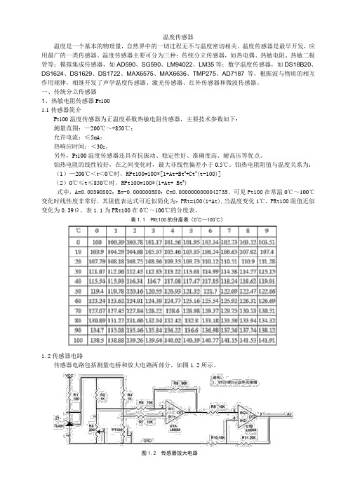
一、传统分立传感器1、热敏电阻传感器Pt1001.1传感器简介Pt100温度传感器为正温度系数热敏电阻传感器,主要技术参数如下:测量范围:—200℃~+850℃;允许电流:≤5mA;热响应时间:<30s。
另外,Pt100温度传感器还具有抗振动、稳定性好、准确度高、耐高压等优点。
铂热电阻的线性较好,在之间变化时,最大非线性偏差小于0.5℃。
铂热电阻阻值与温度关系为:(1)—200℃<t<0℃时,RPt100=100*[1+At+Bt2+Ct3(t-100)](2)0℃≤t≤850℃时,RPt100=100*(1+At+ Bt2)式中,A=0.00390802;B=-0.000000580;C=0.0000000000042735。
可见Pt100在常温0℃~100℃变化时线性度非常好,其阻值表达式可近似简化为:PRt=100(1+At),当温度变化1℃,PRt100阻值近似变化为0.39Ω。
表1.1为PRt100在0℃~100℃的分度表。
表1.1 PRt100的分度表(0℃~100℃)1.2传感器电路传感器电路包括测量电桥和放大电路两部分,如图1.2所示。
图1.2 传感器放大电路图中,R2、R3、R4和Pt100组成传感器测量电桥,为了保证电桥输出电压信号的稳定,电桥的输入电压通过TL431稳至2.5V。
从电桥获取的差分信号通过两级运放放大后输入单片机。
冰箱感温风门组件工作原理

冰箱感温风门组件工作原理
冰箱感温风门组件是冰箱的一个重要部件,它的工作原理如下:
1. 温度传感器测量冰箱内部的温度:冰箱内部安装了一个温度传感器,可以测量冰箱内部的温度。
传感器将温度信号传递给控制电路。
2. 控制电路接收温度信号并判断:控制电路接收温度传感器的信号,并根据事先设定的温度要求进行判断。
如果冰箱内部温度高于设定的温度要求,控制电路会发出指令。
3. 马达控制风门打开或关闭:在接收到控制电路的指令后,马达开始工作。
风门是连接冷冻室和冷藏室的组件,在指令的驱动下,马达会控制风门的打开或关闭。
4. 冷气流动:当风门打开时,冷气可以自由流动从冷冻室进入冷藏室。
这样可以使冷藏室的温度得到降低。
当风门关闭时,冷气的流动被阻止,使得冷藏室的温度维持在设定的要求范围内。
通过以上步骤,冰箱感温风门组件能够根据温度传感器的信号,自动调节冰箱内部的温度,保持冷藏室的温度在设定范围内,实现冷藏和冷冻的功能。
海尔 H-39 温度传感器说明书
0.1 to 3 psi 3.8 psi typ.
500 psi 500 psi
11 A SPDT –
11 A DPDT
DPDT SWITCH
PSW-232 PSW-232D
378 2 to 50 psi 418 2 to 50 psi
0.14 to 3.45 bar 0.14 to 3.45 bar
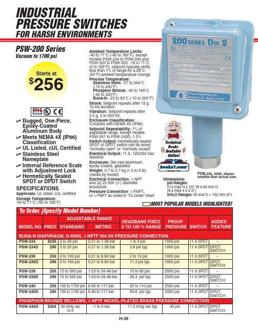
INDUSTRIAL PRESSURE SWITCHES
FOR HARSH ENVIRONMENTS
PSW-200 Series
Vacuum to 1700 psi
Starts at
$256
ߜ Rugged, One-Piece, Epoxy-Coated Aluminum Body
ߜ Meets NEMA 4X (IP66) Classification
400 psi
11 A SPDT –
PSW-225D
454 2.5 to 50 inWC 6.23 to 124.154 mbar 3.6 inWC typ.
400 psi
11 A DPDT
DPDT SWITCH
PSW-226
414 10 to 250 inWC 24.91 to 622.70 mbar 0.4 to 24 inWC
Approvals: UL listed, cUL certified Storage Temperature: -54 to 71°C (-65 to 160°F)
Ambient Temperature Limits: -40 to 71°C (-40 to 160°F), except models PSW-234 to PSW-240 and PSW-520 to PSW-525: -18 to 71°C (0 to 160°F); setpoint typically shifts less than 1% of range for a 28°C (50°F) ambient temperature change
冰箱温控器原理

冰箱温控器原理冰箱温控器是冰箱中的一个重要部件,它的作用是控制冰箱的温度,使冰箱内的食物能够保持在适宜的温度下,从而延长食物的保存时间。
冰箱温控器的原理是通过感应环境温度的变化,调节制冷系统的工作状态,以达到保持冰箱内稳定温度的目的。
冰箱温控器主要由温度传感器、控制电路和执行机构三部分组成。
温度传感器负责感知冰箱内部的温度变化,将温度信号转化为电信号并传输给控制电路。
控制电路根据接收到的温度信号,对制冷系统进行控制,调节制冷系统的运行状态,以维持冰箱内部的稳定温度。
执行机构则是根据控制电路的指令,对制冷系统进行开关控制。
在冰箱运行时,温度传感器不断地感知冰箱内部的温度变化,将感知到的温度信号传输给控制电路。
控制电路根据接收到的温度信号,判断当前温度是否在设定范围内,如果温度超出设定范围,控制电路会发出指令,调节制冷系统的运行状态,使其进行制冷或停止制冷,以维持冰箱内部的稳定温度。
执行机构则根据控制电路的指令,对制冷系统进行开关控制,实现制冷系统的启停。
冰箱温控器的原理可以简单概括为,感知温度、传输信号、控制制冷系统。
通过这一原理,冰箱温控器能够实现对冰箱内部温度的精准控制,保证食物的新鲜度和品质。
除了基本的原理外,冰箱温控器的工作还受到环境温度、制冷系统的性能、食物的存放情况等因素的影响。
在高温环境下,冰箱温控器需要更加频繁地调节制冷系统的运行状态,以保持冰箱内部的稳定温度;制冷系统的性能越好,冰箱温控器的调节精度也会更高;而食物的存放情况则会影响到冰箱内部的温度分布,从而对冰箱温控器的工作产生影响。
总的来说,冰箱温控器是冰箱中的一个关键部件,它通过感知温度、传输信号、控制制冷系统的工作状态,实现对冰箱内部温度的精准控制。
在日常使用中,我们需要注意保持冰箱通风良好、避免阳光直射、定期清洁冰箱等,以确保冰箱温控器的正常工作,延长冰箱的使用寿命,保证食物的新鲜度和安全性。
海尔 J-1J 非接触红外温度传感器说明书
Non-Contact Infrared Temperature SensorWith RS485 ModbuS ® RTu InterfaceoS210-C4 SeriesOptionalU W ide Temperature Range from -20 to 500°C (-4 to 932ºF)Ub uilt-In RS485 ModbuS RTu Interface U C onfigurable Emissivity Setting and Signal Processing U M ax, Min Average and Instantaneous Readings; Peak or Valley Hold; Reflected Energy Compensation U 2:1, 15:1, 30:1 or Close Focus optics U F ast Response with High Stability U S tainless Steel Housing, Sealed to IP65U Q uick and Easy Installation U o ptional Air/Water Cooled Housing, Air Purge Collar, Laser Sighting Tool and Mounting brackets U o ptional dP240 Touch-Screen Terminal for Configuring and displaying data from up to 8 IR SensorsThe OS211 Series is a range of high quality, low cost, compact sensors which measure the temperature of inaccessible or moving objects and materials. They measure temperatures from -20 to 500°C (-4 to 935ºF), accurately and consistently, with an outstanding response time of 240 ms. Two-way digital communications via a built-in RS485 mOdbuS RTu interface enables the user to adjust the emissivity setting; compensate for reflected energy; apply filtering; select maximum and minimum, averageoS211-C4 infrared temperature sensor with dP240 touch screen terminal shown smaller than actual size.Compact stainless steel IP65 housing.or instantaneous readings; and peak or valley hold processing. up to 32 sensors can be installed on a single multidrop network. All the IR sensors are fitted with precision germanium lenses for accurate optics. These compact sensors are small enough to fit almost anywhere and their rugged stainless steel housings make them ideal for applications where cleanliness and hygiene are paramount.The optional dP240 is a 320 x 240 pixel touch screen terminal with a 89 mm (3.5") color TFTdisplay. It allows the user to display data from up to eight infrared sensors and configure each sensor individually. The configuration parameters include emissivity setting, signal averaging, peak or valley hold processing and reflected energy compensation. There are two versions available. Each one provides all of the features above, however, the enhanced dP240-AR also provides analogue transmission for up to 4 sensors, plus two adjustable alarm outputs per sensor for all 8 sensors.DP240-AR DP240Dimensions: mm (in)2 to 6 (0.09 to 0.24)130 (5.12)130 (5.12)50(1.97)40(1.57)4 (0.15)100(3.9)140 (5.5)87(3.4)Panel cut-out 132 x 89(5.20 x 3.5") -0 ±1 mmSpecifications (oS211)Temperature Range: -20 to 500°C(-4 to 932ºF)Interface: RS485 mOdbuS® RTuAccuracy: ±1% of reading or ±1ºCwhichever is greaterRepeatability: ±0.5% of reading or ±0.5ºC whicheveris greaterEmissivity: 0.2 to 1.0Response Time, t90: 240 ms (90% response)Spectral Range: 8 to 14 μmSupply Voltage: 12 Vdc nominal (6 to 13 Vdc)Supply Current: 50 mA maximumbaud Rate: 9600 baud*Format: 8 data bits, no parity, 1 stop bit*MechanicalConstruction: Stainless steeldimensions: 18 d x 103 mm L (0.70 x 4.05")Thread Mounting: m16 x 1 mm pitchCable Length: 1 m (3.3') (longer lengths available to order)Weight with Cable: 95 g (3.35 oz)EnvironmentalRating: IP65Ambient Temperature: 0 to 70ºC (32 to 158ºF)Relative Humidity: 95% max non-condensing* Other configurations available upon requestSpecifications (dP240)display: LCd type TFT 320 x 240, 3.5" touchscreen resistiveSupply Voltage: 12 to 24 VdcPower Consumption: 8 WAmbient Temperature Range: 0 to 45°C (32 to 113ºF)Relative Humidity: 35 to 95%, non-condensingEnvironmental Rating: IP54 front, IP30 housingdimensions:dP240: 140 W x 100 T x 44 mm ddP240-AR: 140 W x 100 T x 65 mm doutputs: (dP240-AR only) 4 analogue outputs, 0 to 10 Vdc,16 programmable alarm outputs,12/24 Vdc, 700 mA,(3 a max per block of 8 outputs)Hardware and Software data Serial Port EXP1:RS485 mOdbuS RTu interface for infrared sensorsSerial Port CoM2: RS485/RS232 interface for seconddisplay (read only)130 (5.12)130 (5.12)50(1.97)40(1.57)4 (0.15)100(3.9)140 (5.5)87(3.4)Panel cut-out 132 x 89(5.20 x 3.5") -0 ±1 mm130 (5.12)50(1.97)40(1.57)4 (0.15)100(3.9)140 (5.5)87(3.4)Panel cut-out 132 x 89(5.20 x 3.5") -0 ±1 mmPower Supply130 (5.12)50(1.97)40(1.57)4 (0.15)100(3.9)140 (5.5)87(3.4)Panel cut-out 132 x 89(5.20 x 3.5") -0 ±1 mmOMEGACARE SM extended warranty program isavailable for models shown on this page. Ask yoursales representative for full details when placingan order. OMEGACARE SM covers parts, labor andequivalent loaners.oS210-LSTL.oS210-FbL.oS210-APL.oS210-AbL.Fixed Mounting bracketAdjustable Mounting bracketThe adjustable mounting bracket consists of a fixed mounting bracket plus another L-shapedbracket. When assembled as shown the adjustable mounting bracket offers a rigid support for the sensor and allows fine adjustment in two planes.Air Purge CollarThe laser sighting tool screws onto the front of the sensor during installationComes complete with sensor head, 1 m (3.3') cable, USB cable, software, and operator’s manual.Ordering Examples: OS151-C4, configurable infrared temperature sensor with 15:1 optics and RS485 MOdBUS ® RTU interface.OS211-C4-CE(3), configurable infrared temperature sensor with 2:1 optics and RS485 MOdBUS ® RTU interface and 3 m (9.8') of additional extension cable. OCW-3, OMEGACARE SM extends standard 2 year warranty to a total 5 years.1 m (3.3') cable is included as standard on every sensor. Extended cable is added to that length, add suffix to model number. Insert cable length in meters.。
海尔冰箱传感器资料
海尔冰箱传感器资料F1 冷藏蒸发器传感器短路或开路F2 环境温度传感器短路或开路F3 冷藏空间传感器短路或开路F4 冷冻温度传感器短路或开路F5 负7度温度传感器短路或开路传感器培训教材一、定义及原理:1、一组定义:冰箱及其他家电行业普遍使用温度传感器作为感受特定部位温度并通过控制系统转换成电信号来控制系统按规定模式运行,冰箱及其他家电行业使用的传感器主要为直热式负温度系数热敏电阻器。
①热敏电阻器定义:电阻值随其阻体温度变化而变化的热敏感半导体电阻器;热敏电阻器有正温度系数热敏电阻器、负温度系数热敏电阻器②负温度系数(NTC)热敏电阻器:在工作范围内,零功率电阻值随温度增加而减小的热敏电阻。
③直热式热敏电阻器:不带加热器的热敏电阻器④直热式负温度系数热敏电阻器:是由电流通过热敏元件和(或)由环境温度的变化而获得其阻值变化的负温度系数热敏电阻器⑤绝缘型热敏电阻器:能经受试验规范所规定的绝缘电阻和耐电压试验的热敏电阻器2、一组特性参数:①零功率电阻值:在规定温度下测量热敏电阻器的电阻值,由于电阻体内部发热引起的电阻值变化相对于总的测量误差来说可以忽略不计时测得的电阻值②最大电压;在环境温下,不使热敏电阻器引起失控所允许连续施加的最大直流电压③耗散系数δ:在规定环境条件下,热敏电阻器耗散功率的变化与热敏电阻体相应温度变化之比。
④δ-热敏系数τ:在零功率条件下,当温度发生突变时,热敏电阻体的温度变化了始末两个温度差的63.2%所需的时间⑤绝缘电阻:在规定环境条件下,直热式热敏电阻器连在一起的引出端与外层封装面之间的直流电阻值⑥绝缘电压:在连续工作条件下,允许加到直热式热敏电阻器连在一起的引出端与外层封装面之间的最高峰电压⑦电阻-温度特性负温度系数热敏电阻器的电阻温度特性可用下式近似表示R=Ae(BT)R---温度为T时热敏电阻器的电阻值A---与热敏电阻器材料物理特性和几何尺寸有关的系数T---绝对温度(K)B---热敏系数:在两个温度下零功率电阻值的自然对数之差与两温度倒数之差的比值,B=T1*T2/(T2-T1)㏑(R1/R2)二、海尔传感器特点及安装注意要点a) 海尔冰箱使用的传感器有两大类i. 冷藏用传感器:引线为白色,感温头有圆头和方头两种ii. 冷冻用传感器:引线为黑色,使用时感温头外部封装有黑色热缩套。
电冰箱温度传感器
摘要近年来随着计算机在社会领域的渗透,EDA的应用正在不断地走向深入,设计者在E DA软件平台上,用硬件描述语言VHDL完成电冰箱温度控制系统设计。
在实时检测和自动控制的应用系统中,电冰箱温度控制系统是利用温度传感器DS18B20采集电冰箱冷藏室和冷冻室的温度,利用EDA技术,从而达到智能控制的目的。
本系统可实现电冰箱冷藏室和冷冻室的温度设置、开门报警等功能。
本文在第一章介绍了电冰箱的系统组成及工作原理,第二章论述了本控制系统的硬件设计部分。
第三章论述了系统的软件设计部分。
通过对直冷式电冰箱制冷系统的改进,实现了电冰箱的双温双控,使电冰箱能根据使用条件的变化迅速合理地调节制冷量,且节能效果良好。
IP核往往是作为一个核心部件来使用,所以单片机方面知识是不够的,还应根据具体硬件结构,以及针对具体应用对象特点的软件结合,以作完善。
关键词:EDA 温度传感器电冰箱温度控制ⅠAbstractWith the infiltration in the social field of the computer in recent years, the appli cation of EDA is moving towards deepening constantly, drive tradition is it measure cr escent benefit to upgrade day to control at the same time.. The electric refrigerator te mperature control system is uses the temperature sensor DS18B20 gathering electric ref rigerator cold-storageroom and the freezing room temperature, use the EDA technology thus achieves the intelligent control the goal. This system may realize the electric refri gerator cold-storageroom and the freezing room temperature establishment, the electric r efrigerator automatically defrosts, opens the gate to report to the police and so on the function.This article introduced in the first chapter the electric refrigerator system compositi on and the principle of work, the second chapter elaborated this control system hardwa re design part. Third chapter elaborated the system software design part.By improving the refrigerating system of refrigerator and applying the vague-contr ol technology, the goal of double-temperature, double-control has been realized;it makes possible for the refrigerator to regulate the amount of cold air in a speedy and ration al way. Thus, power saving is availableIn measuring in real time and automatically controlled one-chip computer applicati on system, the one-chip computer often uses as a key part, only one-chip computer res pect knowledge is not enough, should also follow the structure of the concrete hardwar e , and direct against and use the software of target's characteristic to combine concretl y, in order to do perfectlyKey words:EDA; The temperature sensor ;The electric refrigerator;Temperature contr olⅡ目录摘要 (Ⅰ)ABSTRACT (Ⅱ)目录 (Ⅲ)引言 (1)1 总的设计方案 (2)1.1总体方案简介 (2)1.2方案选择 (6)2系统硬件设计 (7)2.1系统结构图 (7)2.2微处理器 (8)2.3温度传感器 (9)2.4LED简介 (11)2.5功能按键 (11)2.6压缩机,风机,电磁阀控制 (12)2.7过欠压保护 (13)3 EDA设计 (14)3.1VHDL顶层设计 (14)3.2传感器产生信号CLK (15)3.3计时模块 (16)3.4显示模块 (18)4技术总结 (25)5结束语 (26)6参考文献 (27)7致谢 (28)Ⅲ引言现代工业设计、工程建设及日常生活中常常需要用到温度控制,早期温度控制主要应用于工厂中,例如钢铁的水溶温度,不同等级的钢铁要通过不同温度的铁水来实现,这样就可能有效的利用温度控制来掌握所需要的产品了。
冰箱电器件介绍
图中1:干簧管2:磁环3:外壳4:引线磁控温度开关的动作原理:干簧管又称为磁簧开关,是一种密封的磁控性机械开关,磁环为一种铁磁材料(又称铁氧体),根据电磁学原理,任何铁磁物质都有一个临界温度,高于这个温度的铁磁性就消失。
这个临界温度叫做铁磁质的居里点,磁控温度开关中的磁环通过材料配方使其居里点在10℃~14℃。
则环境温度低于10℃时磁环的磁性恢复,干簧管触点动作闭合,环境温度高于14℃时磁环的磁性消失,干簧管触点断开。
温度熔断器温度熔断器使用在无霜冰箱的加热化霜回路中,是一种超温保护用的安全元件,避免因为加热化霜控制回路故障导致的高温及火灾隐患。
当温度达到设定温度时,它能够发生一次性动作而不能复位。
在冰箱中使用的温度熔断器的动作温度一般为72℃。
图示为内部结构,1:陶瓷绝缘2:星形触片3:热敏丸4:引线5:外壳6:断路弹簧7:压缩弹簧工作原理:为弹簧反应式有机化合物温度熔断器。
从图中可以看出,在动作前,引线与触电片在断路弹簧与压缩弹簧的压力下保持良好的接触,并通过外壳构成导电通路。
当温度熔断器感受到的温度超过动作温度时,感温体(热敏丸)熔融,压缩弹簧释放,在断路弹簧推力作用下,引线与触片迅速脱离,切断电源,起到保护作用。
这种温度熔断器的感温体不会变质,稳定性好,动作温度精度高,电流容量也较大,同时响应速度快。
但应用中应注意外壳带电。
双稳态电磁阀(二位三通电磁阀)二位三通电磁阀用于在冰箱中通过电路切换制冷系统的走向。
传统二位三通电磁阀有两个状态,即通电时一个状态,断电时为另一个状态。
图中的两块磁铁安装时保持极性相对的状态,这样钢质阀芯在磁力线正对的位置被排斥而只能保持在左或右的位置,当外部的线圈通电时,可使阀芯根据驱动脉冲的极性克服磁铁的磁力转换到对应位置。
双稳态电磁阀通过磁保持在不通电时在两个位置均能保持稳定状态,即平时不耗电,仅在换向时瞬时耗电,无驱动脉冲及断电后均保持原状态。
所以具有省电、线圈不发热、可靠性高等优点。
- 1、下载文档前请自行甄别文档内容的完整性,平台不提供额外的编辑、内容补充、找答案等附加服务。
- 2、"仅部分预览"的文档,不可在线预览部分如存在完整性等问题,可反馈申请退款(可完整预览的文档不适用该条件!)。
- 3、如文档侵犯您的权益,请联系客服反馈,我们会尽快为您处理(人工客服工作时间:9:00-18:30)。
海尔冰箱温度传感器资料时间:2010-04-10 10:31来源:未知作者:admin 点击: 185次F1 冷藏蒸发器传感器短路或开路 F2 环境温度传感器短路或开路 F3 冷藏空间传感器短路或开路 F4 冷冻温度传感器短路或开路 F5 负7度温度传感器短路或开路传感器培训教材一、定义及原理: 1、一组定义:冰箱及其他家电行业普遍使用温度传感器作为感受特定部F1 冷藏蒸发器传感器短路或开路F2 环境温度传感器短路或开路F3 冷藏空间传感器短路或开路F4 冷冻温度传感器短路或开路F5 负7度温度传感器短路或开路传感器培训教材一、定义及原理:1、一组定义:冰箱及其他家电行业普遍使用温度传感器作为感受特定部位温度并通过控制系统转换成电信号来控制系统按规定模式运行,冰箱及其他家电行业使用的传感器主要为直热式负温度系数热敏电阻器。
①热敏电阻器定义:电阻值随其阻体温度变化而变化的热敏感半导体电阻器;热敏电阻器有正温度系数热敏电阻器、负温度系数热敏电阻器②负温度系数(NTC)热敏电阻器:在工作范围内,零功率电阻值随温度增加而减小的热敏电阻。
③直热式热敏电阻器:不带加热器的热敏电阻器④直热式负温度系数热敏电阻器:是由电流通过热敏元件和(或)由环境温度的变化而获得其阻值变化的负温度系数热敏电阻器⑤绝缘型热敏电阻器:能经受试验规范所规定的绝缘电阻和耐电压试验的热敏电阻器2、一组特性参数:① 零功率电阻值:在规定温度下测量热敏电阻器的电阻值,由于电阻体内部发热引起的电阻值变化相对于总的测量误差来说可以忽略不计时测得的电阻值② 最大电压;在环境温下,不使热敏电阻器引起失控所允许连续施加的最大直流电压③ 耗散系数δ:在规定环境条件下,热敏电阻器耗散功率的变化与热敏电阻体相应温度变化之比。
④ δ-热敏系数τ:在零功率条件下,当温度发生突变时,热敏电阻体的温度变化了始末两个温度差的63.2%所需的时间⑤ 绝缘电阻:在规定环境条件下,直热式热敏电阻器连在一起的引出端与外层封装面之间的直流电阻值⑥ 绝缘电压:在连续工作条件下,允许加到直热式热敏电阻器连在一起的引出端与外层封装面之间的最高峰电压⑦ 电阻-温度特性负温度系数热敏电阻器的电阻温度特性可用下式近似表示R=Ae(BT)R---温度为T时热敏电阻器的电阻值A---与热敏电阻器材料物理特性和几何尺寸有关的系数T---绝对温度(K)B---热敏系数:在两个温度下零功率电阻值的自然对数之差与两温度倒数之差的比值,B=T1*T2/(T2-T1)㏑(R1/R2)二、海尔传感器特点及安装注意要点a) 海尔冰箱使用的传感器有两大类i. 冷藏用传感器:引线为白色,感温头有圆头和方头两种ii. 冷冻用传感器:引线为黑色,使用时感温头外部封装有黑色热缩套。
b) 冷冻、冷藏传感器温度参数表冷冻传感器阻值对应表偏差 2%温度下限值基准值上限值温度下限值基准值上限值-30 32.78 33.84 34.920 20 2.346 2.493 2.648-29 30.92 31.88 32.860 21 2.241 2.384 2.534-28 29.17 30.04 30.930 22 2.141 2.280 2.426-27 27.53 28.32 29.120 23 2.047 2.180 2.322-26 25.99 26.7 27.420 24 1.956 2.086 2.224-25 24.54 25.19 25.840 25 1.871 1.997 2.130-24 23.18 23.77 24.350 26 1.789 1.911 2.041-23 21.91 22.43 22.960 27 1.712 1.830 1.956-22 20.71 21.18 21.650 28 1.638 1.753 1.875-21 19.58 20 20.430 29 1.568 1.679 1.798-20 18.52 18.9 19.280 30 1.501 1.609 1.724-19 17.49 17.86 18.240 31 1.437 1.542 1.654-18 16.51 16.89 17.260 32 1.377 1.478 1.587-17 15.60 15.97 16.340 33 1.319 1.418 1.523-16 14.74 15.11 15.480 34 1.264 1.360 1.462-15 13.93 14.3 14.660 35 1.212 1.304 1.404-14 13.17 13.53 13.900 36 1.162 1.252 1.348-13 12.46 12.81 13.170 37 1.114 1.201 1.295-12 11.79 12.14 12.490 38 1.069 1.153 1.244 -11 11.16 11.5 11.850 39 1.026 1.108 1.196 -10 10.56 10.9 11.240 40 0.984 1.064 1.149 -9 10.01 10.33 10.670 41 0.945 1.022 1.105 -8 9.479 9.800 10.130 42 0.907 0.982 1.063 -7 8.982 9.296 9.618 43 0.871 0.944 1.022 -6 8.514 8.821 9.136 44 0.837 0.908 0.984 -5 8.073 8.373 8.681 45 0.804 0.873 0.947 -4 7.657 7.950 8.251 46 0.773 0.839 0.911 -3 7.265 7.551 7.844 47 0.743 0.808 0.877 -2 6.895 7.173 7.460 48 0.714 0.777 0.845 -1 6.546 6.817 7.097 49 0.687 0.748 0.8140 6.216 6.480 6.753 50 0.661 0.720 0.7841 5.905 6.162 6.427 51 0.636 0.693 0.7552 5.610 5.861 6.119 52 0.612 0.668 0.7283 5.332 5.576 5.828 53 0.589 0.643 0.7024 5.070 5.306 5.552 54 0.567 0.620 0.6775 4.821 5.051 5.290 55 0.546 0.597 0.6536 4.586 4.810 5.042 56 0.526 0.576 0.6307 4.364 4.581 4.807 57 0.507 0.555 0.6078 4.154 4.365 4.584 58 0.488 0.535 0.5869 3.955 4.160 4.373 59 0.471 0.516 0.56610 3.766 3.965 4.173 60 0.454 0.498 0.54611 3.588 3.781 3.983 61 0.437 0.480 0.52712 3.419 3.606 3.802 62 0.422 0.464 0.50913 3.259 3.440 3.631 63 0.407 0.448 0.49214 3.107 3.283 3.468 64 0.393 0.432 0.47515 2.963 3.134 3.313 65 0.379 0.417 0.45916 2.826 2.992 3.167 66 0.366 0.403 0.44417 2.697 2.858 3.027 67 0.353 0.389 0.42918 2.574 2.730 2.894 68 0.341 0.376 0.41519 2.457 2.609 2.768 69 0.329 0.364 0.401 温度下限值基准值上限值70 0.318 0.351 0.38871 0.307 0.340 0.37672 0.297 0.329 0.36373 0.287 0.318 0.35274 0.277 0.307 0.34175 0.268 0.297 0.33076 0.259 0.288 0.31977 0.251 0.279 0.30978 0.243 0.270 0.30079 0.235 0.261 0.29080 0.227 0.253 0.28181 0.220 0.245 0.27382 0.213 0.237 0.26483 0.206 0.230 0.25684 0.200 0.223 0.24885 0.194 0.216 0.24186 0.188 0.209 0.23487 0.182 0.203 0.22788 0.176 0.197 0.22089 0.171 0.191 0.21490 0.166 0.185 0.20791 0.161 0.180 0.20192 0.156 0.175 0.19693 0.151 0.169 0.19094 0.147 0.165 0.18595 0.142 0.160 0.17996 0.138 0.155 0.17497 0.134 0.151 0.16998 0.130 0.146 0.16599 0.126 0.124 0.160100 0.123 0.138 0.156冷藏传感器阻值对应表偏差 2%温度下限值基准值上限值温度下限值基准值上限值-30 31.36 33.07 34.86 20 2.352 2.446 2.543-29 29.58 31.16 32.81 21 2.247 2.339 2.434-28 27.91 29.37 30.89 22 2.147 2.237 2.330-27 26.35 27.69 29.09 23 2.052 2.140 2.231-26 24.88 26.12 27.40 24 1.962 2.047 2.136-25 23.50 24.64 25.82 25 1.876 1.960 2.046-24 22.20 23.25 24.34 26 1.794 1.876 1.961-23 20.99 21.95 22.95 27 1.717 1.796 1.879-22 19.84 20.73 21.65 28 1.643 1.721 1.802-21 18.76 19.58 20.43 29 1.573 1.649 1.727-20 17.75 18.50 19.28 30 1.506 1.580 1.657-19 16.79 17.49 18.20 31 1.442 1.514 1.590-18 15.90 16.54 17.19 32 1.381 1.452 1.525-17 15.05 15.64 16.24 33 1.324 1.392 1.464-16 14.26 14.80 15.35 34 1.269 1.336 1.405-15 13.51 14.00 14.51 35 1.216 1.281 1.350-14 12.80 13.25 13.72 36 1.166 1.230 1.296-13 12.13 12.55 12.98 37 1.119 1.181 1.245-12 11.51 11.89 12.28 38 1.073 1.134 1.197-11 10.91 11.27 11.62 39 1.030 1.089 1.150-10 10.36 10.68 11.00 40 0.988 1.046 1.106-9 9.828 10.12 10.42 41 0.949 1.005 1.063-8 9.331 9.60 9.874 42 0.911 0.966 1.023-7 8.861 9.108 9.357 43 0.875 0.928 0.984-6 8.418 8.643 8.870 44 0.841 0.892 0.947-5 7.999 8.204 8.411 45 0.808 0.858 0.911-4 7.603 7.790 7.978 46 0.777 0.826 0.877-3 7.228 7.398 7.569 47 0.747 0.794 0.845-2 6.874 7.029 7.184 48 0.718 0.764 0.813-1 6.540 6.680 6.820 49 0.691 0.736 0.7830 6.223 6.350 6.477 50 0.664 0.708 0.7551 5.911 6.038 6.165 51 0.639 0.682 0.7272 5.617 5.743 5.870 52 0.615 0.657 0.7013 5.339 5.464 5.590 53 0.592 0.633 0.6764 5.076 5.201 5.326 54 0.570 0.610 0.6525 4.828 4.951 5.075 55 0.549 0.588 0.6296 4.593 4.714 4.837 56 0.529 0.567 0.6067 4.370 4.491 4.612 57 0.510 0.546 0.5858 4.160 4.279 4.399 58 0.491 0.527 0.5659 3.961 4.078 4.196 59 0.473 0.508 0.54510 3.772 3.887 4.004 60 0.456 0.490 0.52611 3.504 3.707 3.822 61 0.440 0.473 0.50812 3.425 3.536 3.649 62 0.424 0.457 0.49113 3.261 3.373 3.485 63 0.409 0.441 0.47414 3.112 3.219 3.329 64 0.395 0.426 0.45815 2.968 3.073 3.181 65 0.381 0.411 0.44316 2.832 2.935 3.040 66 0.368 0.397 0.42817 2.702 2.803 2.906 67 0.355 0.384 0.41418 2.579 2.678 2.779 68 0.343 0.371 0.40019 2.463 2.559 2.658 69 0.331 0.358 0.387c) 安装注意要点i. 各传感器感温头必须安装在设计规定的固定夹内,冷藏蒸发器传感器、-7度传感器必须紧贴到蒸发器板上,方向位置要正确,其中冷藏蒸发器传感器为方形感温头,为提高感温灵敏性感温元件是偏向一侧设置的,其对立面上有“Haier”标记,固定时必须将带“Haier”标记的对立面紧贴在蒸发器板上.ii. 传感线及感温头部分必须密封完好,无破损、折裂避免水分入侵,造成参数漂移;传感线不能被感温盘压住,应从感温盘的缺口中穿出。