Maxon 直流电机样本10_EN_EC45
沃伦森电气
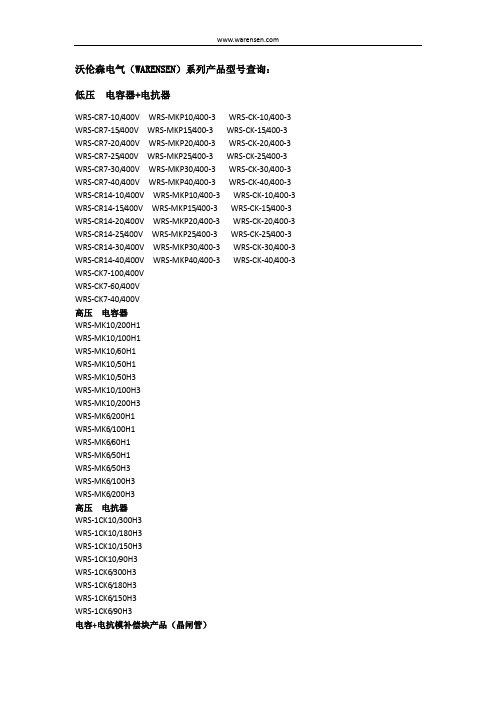
沃伦森电气(WARENSEN)系列产品型号查询:低压电容器+电抗器WRS-CR7-10/400V WRS-MKP10/400-3 WRS-CK-10/400-3 WRS-CR7-15/400V WRS-MKP15/400-3 WRS-CK-15/400-3 WRS-CR7-20/400V WRS-MKP20/400-3 WRS-CK-20/400-3 WRS-CR7-25/400V WRS-MKP25/400-3 WRS-CK-25/400-3 WRS-CR7-30/400V WRS-MKP30/400-3 WRS-CK-30/400-3 WRS-CR7-40/400V WRS-MKP40/400-3 WRS-CK-40/400-3 WRS-CR14-10/400V WRS-MKP10/400-3 WRS-CK-10/400-3 WRS-CR14-15/400V WRS-MKP15/400-3 WRS-CK-15/400-3 WRS-CR14-20/400V WRS-MKP20/400-3 WRS-CK-20/400-3 WRS-CR14-25/400V WRS-MKP25/400-3 WRS-CK-25/400-3 WRS-CR14-30/400V WRS-MKP30/400-3 WRS-CK-30/400-3 WRS-CR14-40/400V WRS-MKP40/400-3 WRS-CK-40/400-3 WRS-CK7-100/400VWRS-CK7-60/400VWRS-CK7-40/400V高压电容器WRS-MK10/200H1WRS-MK10/100H1WRS-MK10/60H1WRS-MK10/50H1WRS-MK10/50H3WRS-MK10/100H3WRS-MK10/200H3WRS-MK6/200H1WRS-MK6/100H1WRS-MK6/60H1WRS-MK6/50H1WRS-MK6/50H3WRS-MK6/100H3WRS-MK6/200H3高压电抗器WRS-1CK10/300H3WRS-1CK10/180H3WRS-1CK10/150H3WRS-1CK10/90H3WRS-1CK6/300H3WRS-1CK6/180H3WRS-1CK6/150H3WRS-1CK6/90H3电容+电抗模补偿块产品(晶闸管)WRS-CRT7-30/1-400VWRS-CRT7-60/2-400VWRS-CRT7-60/1-400VWRS-CRT7-90/1-400VWRS-CRT7-60/1-400VWRS-CRT7-90/1-400VWRS-CRT7-60/2-400VWRS-CRT7-60/1-400VWRS-CRT7-90/1-400VWRS-CRT7-60/1-400VWRS-CRT7-90/1-400VWRS-CRT7-60/1-400VWRS-CRT7-90/1-400VWRS-CRT7-90/1-400VWRS-CKT7-240/4-400VWRS-CKT7-360/6-400VWRS-CRT14-30/2-400VWRS-CRT14-30/2-400VWRS-CRT14-30/1-400VWRS-CRT14-30/2-400VWRS-CRT14-60/2-400VWRS-CRT14-60/2-400VWRS-CRT14-60/1-400VWRS-CRT14-60/2-400VWRS-CRT14-60/1-400VWRS-CRT14-60/2-400VWRS-CRT14-90/1-400VWRS-CRT14-60/2-400VWRS-CRT14-60/1-400VWRS-CRT14-90/1-400VWRS-CRT14-60/2-400VWRS-CRT14-60/1-400VWRS-CRT14-90/1-400VWRS-CRT14-60/1-400VWRS-CRT14-90/1-400VWRS-CRT14-60/1-400VWRS-CRT14-90/1-400VWRS-CKT14-240/4-400VWRS-CKT14-360/6-400V电容+电抗补偿模块产品(接触器)WRS-CRS7-30/2-400VWRS-CRS7-30/2-400VWRS-CRS7-30/1-400VWRS-CRS7-60/2-400VWRS-CRS7-60/2-400VWRS-CRS7-60/1-400VWRS-CRS7-60/2-400VWRS-CRS7-60/1-400VWRS-CRS7-60/2-400VWRS-CRS7-90/1-400VWRS-CRS7-60/2-400VWRS-CRS7-60/1-400VWRS-CRS7-90/1-400VWRS-CRS7-60/2-400VWRS-CRS7-60/1-400VWRS-CRS7-60/1-400VWRS-CRS7-90/1-400VWRS-CKS7-240/4-400VWRS-CKS7-360/6-400VWRS-CRS14-30/2-400VWRS-CRS14-30/1-400VWRS-CRS14-60/2-400VWRS-CRS14-60/1-400VWRS-CRS14-60/2-400VWRS-CRS14-60/1-400VWRS-CRS14-60/2-400VWRS-CRS14-90/1-400VWRS-CRS14-60/2-400VWRS-CRS14-60/1-400VWRS-CRS14-60/2-400VWRS-CRS14-60/1-400VWRS-CRS14-90/1-400VWRS-CRS14-90/1-400VWRS-CRS14-60/1-400VWRS-CKS14-240/4-400VWRS-CKS14-360/6-400V纯电容补偿模块产品(晶闸管)WRS-CT7-30/2-400VWRS-CT7-30/1-400VWRS-CT7-60/2-400VWRS-CT7-60/1-400VWRS-CT7-90/1-400VWRS-CT7-100/1-400V纯电容补偿模块产品(接触器)WRS-CS7-30/2-400VWRS-CS7-30/1-400VWRS-CS7-60/1-400V WRS-CS7-90/1-400V WRS-CS7-100/1-400V智能电容器WRS-IC-450/10WRS-IC-450/15WRS-IC-450/20WRS-IC-450/25WRS-IC-450/30WRS-IC-450/40WRS-IC-450/50WRS-IC-450/60WRS-IC-450/70智能电容器(电抗器)WRS-ICR7-480/10WRS-ICR7-480/15WRS-ICR7-480/20WRS-ICR7-480/24WRS-ICR7-480/30WRS-ICR7-480/35WRS-ICR7-480/40WRS-ICR7-480/45WRS-APF模块产品WRS-APF25/400VWRS-APF35/400VWRS-APF50/400VWRS-APF60/400VWRS-APF75/400VWRS-APF100/400VWRS-SVG模块产品WRS-SVG50/400VWRS-SVG100/400V静止无功发生器WRS-SVG WDSVG-12/1000-N WDSVG-12/2000-N磁控式动态补偿滤波装置WMSVC-12/600-600-N WMSVC-12/1000-1000-N WMSVC-12/1200-1200-N WMSVC-12/600-600-W WMSVC-12/1000-1000-W WMSVC-12/1200-1200-W 高压无功补偿装置WMC-12/1000-3N WMC-12/1200-4N WMC-12/1600-4N WMC-12/2000-5N WMC-6/1000-3W WMC-6/1200-4W WMC-6/1600-4W WMC-6/2000-5WWMC-12/180-1N WMC-12/200-1N WMC-12/300-1N WMC-6/180-1N WMC-6/200-1N WMC-6/300-1N高压线路装置WMXC-6/50+100J WMXC-6/100+100J WMXC-6/200+100J WMXC-6/100+200J WMXC-6/100+100 WMXC-12/50+100J WMXC-12/100+100J WMXC-12/200+100J WMXC-12/100+200J WMXC-12/100+100 低压有源滤波装置WUAPF-400/50-2N WUAPF-400/75-2N WUAPF-400/100-3N WUAPF-400/125-3N WUAPF-400/150-3N WUAPF-400/200-4N 低压无功补偿装置WMTC-400/90-4N WMTC-400/120-3N WMTC-400/180-4N WMTC-400/240-4N WMTC-400/300-5N WMTC-400/360-6N WMTC-400/480-6N 低压无源滤波装置WTSF400-100/3-N WTSF400-200/4-N WTSF400-300/5-N低压控制器WRS-DK-12TWRS-DK-21TWRS-DK-12SWRS-DK-21S高压控制器WRS-HK-700智能电容器控制器WRS-IK-200电容器综合保护单元WRS-HB-1000电能质量在线监测装置WRS-600S动态补偿调节开关WRS-TD1永磁式电容投切真空开关WRS-ZNT12/630-Y多功能电力仪表WRS650AA-9K1WRS650AV-9K1WRS650AA-9K4WRS650AV-9K4WRS650-AE-9WRS650E-9SUIWRS650E-9SUIYWRS650E-9S4WRS650E-9SYWRS650Z-9H4WRS650Z-9HYWRS650Z-9FYWRS730E-9S4WRS730AA-9K4WRS730E-9SUIWRS780M(P)M:塑壳P:金属壳导轨式电能表WRSDS11WRSDS111WRSDS111EWRSDS111EFWRSTS333WRSTS333EWRSTS333EF电力监控组态软件WRS-1000综合智能操控装置WRS-910WRS-920WRS-930WRS-940WRS-950导轨式预付费电能表单相:DDS8500Y-BJ三相:DTS8500Y-BJ WRS-DDS580Y-DT WRS-DDS580Y-DK WRS-DDS580Y-DH WRS-DDS580Y-DTP WRS-DDS580Y-DKP WRS-DDS580Y-DHP WRS-DTS580Y-DT WRS-DTS580Y-DK WRS-DTS580Y-DH用电管理系统WRS-A型用电管理系统WRS-B型用电管理系统WRS-C型用电管理系统WRS-D型用电管理系统谐波保护器WRS-BMS100-400V WRS-BMS500-400V WRS-BMS1000-400V WRS-BMS1000E-400V。
美达尔Moeller系列U-PKZ0欠压发电器说明书
Eaton 073145Eaton Moeller® series U-PKZ0 Undervoltage release PKZ0(4),PKE, AC, 208 V 60 Hz, Screw terminalsEspecificaciones generalesEaton Moeller® series U-PKZ0Accessory Undervoltage Release073145401508073145068 mm90 mm24 mm0.129 kgCECSA File No.: 165628UL 508CSAULUL File No.: E36332CSA-C22.2 No. 14UL Category Control No.: NLRV IEC/EN 60947-4-1CSA Class No.: 3211-05U-PKZ0(208V60HZ)Product Name Catalog NumberEANProduct Length/Depth Product Height Product Width Product Weight Certifications Model CodeScrew connection Can be fitted to left side of the motor protection switchAccessoriesEMERGENCY STOP or EMERGENCY switching-off device inaccordance with IEC/EN 60204 when combined with circuitbreakerMotor safety switchMotor protective circuit-breakerAC-25 °C 55 °C 2 x (0.75 - 2.5) mm² 1 x (0.75 - 2.5) mm²1 x (18 - 14)2 x (18 - 14)42 V 480 V 24 V 250 V 0,7- 0,35 x Uc 0.85 - 1.1 V x Uc 0 V0 V208 VElectric connection type Mounting positionProduct categorySuitable asSuitable forUsed withVoltage typeAmbient operating temperature - minAmbient operating temperature - maxTerminal capacity (solid/flexible with ferrule)Terminal capacity (solid/stranded AWG)Rated operational voltage (Ue) at AC - min Rated operational voltage (Ue) at AC - max Rated operational voltage (Ue) at DC - min Rated operational voltage (Ue) at DC - max Drop-out voltagePick-up voltageRated control supply voltage (Us) at AC, 50 Hz - min Rated control supply voltage (Us) at AC, 50 Hz - max Rated control supply voltage (Us) at AC, 60 Hz - min Rated control supply voltage (Us) at AC, 60 Hz - max208 V0 V0 V5 VA, Pull-in power, Coil in a cold state and 1.0 x Us 5 VA, Pull-in power, Coil in a cold state and 1.0 x Us 3 VA, Coil in a cold state and 1.0 x Us3 VA, Coil in a cold state and 1.0 x Us 0 W0 W0 W0 A0.5 WMeets the product standard's requirements.Meets the product standard's requirements.Meets the product standard's requirements.Meets the product standard's requirements.Meets the product standard's requirements.Does not apply, since the entire switchgear needs to be evaluated.Does not apply, since the entire switchgear needs to be evaluated.Rated control supply voltage (Us) at DC - minRated control supply voltage (Us) at DC - maxNumber of contacts (change-over contacts)Number of contacts (normally closed contacts)Number of contacts (normally open contacts)Power consumption, pick-up, 50 Hz Power consumption, pick-up, 60 Hz Power consumption, sealing, 50 Hz Power consumption, sealing, 60 Hz Equipment heat dissipation, current-dependent PvidHeat dissipation capacity PdissHeat dissipation per pole, current-dependent PvidRated operational current for specified heat dissipation (In) Static heat dissipation, non-current-dependent Pvs10.2.2 Corrosion resistance10.2.3.1 Verification of thermal stability of enclosures10.2.3.2 Verification of resistance of insulating materials to normal heat10.2.3.3 Resist. of insul. mat. to abnormal heat/fire by internal elect. effects10.2.4 Resistance to ultra-violet (UV) radiation10.2.5 Lifting10.2.6 Mechanical impactMeets the product standard's requirements.Does not apply, since the entire switchgear needs to be evaluated.Meets the product standard's requirements.Does not apply, since the entire switchgear needs to be evaluated.Does not apply, since the entire switchgear needs to be evaluated.Is the panel builder's responsibility.Is the panel builder's responsibility.Is the panel builder's responsibility.Is the panel builder's responsibility.Is the panel builder's responsibility.The panel builder is responsible for the temperature rise calculation. Eaton will provide heat dissipation data for the devices.Is the panel builder's responsibility. The specifications for the switchgear must be observed.Is the panel builder's responsibility. The specifications for the switchgear must be observed.The device meets the requirements, provided the information in the instruction leaflet (IL) is observed.DA-DC-00004882.pdfDA-DC-00004892.pdfDA-DC-00004886.pdfDA-DC-00004787.pdfDA-DC-00004879.pdfDA-DC-00004911.pdfDA-DC-00004912.pdfDA-DC-00004935.pdfDA-DC-00004910.pdfDA-DC-00004951.pdfDA-DC-00004915.pdfDA-DC-00004921.pdfDA-DC-00004851.pdfDA-DC-00004883.pdfDA-DC-00004878.pdfDA-DC-00004890.pdfDA-DC-00004913.pdfDA-DC-00004962.pdfDA-DC-00004937.pdfDA-DC-00004952.pdfDA-DC-00004960.pdfDA-DC-00004884.pdfDA-DC-00004945.pdfDA-DC-00004880.pdfDA-DC-00004891.pdfDA-DC-00004920.pdfDA-DC-00004961.pdfDA-DC-00004881.pdfDA-DC-00004953.pdfDA-DC-00004944.pdfDA-DC-00004914.pdfeaton-manual-motor-starters-release-u-pkz0-accessory-dimensions.eps eaton-manual-motor-starters-release-u-pkz0-accessory-3d-drawing.eps eaton-manual-motor-starters-shunt-releases-u-pkz0-accessory-3d-drawing.eps10.2.7 Inscriptions10.3 Degree of protection of assemblies10.4 Clearances and creepage distances10.5 Protection against electric shock10.6 Incorporation of switching devices and components10.7 Internal electrical circuits and connections10.8 Connections for external conductors10.9.2 Power-frequency electric strength10.9.3 Impulse withstand voltage10.9.4 Testing of enclosures made of insulating material10.10 Temperature rise10.11 Short-circuit rating10.12 Electromagnetic compatibility10.13 Mechanical functionDeclarations of conformityDibujosEaton Corporation plc Eaton House30 Pembroke Road Dublin 4, Ireland © 2023 Eaton. All Rights Reserved. Eaton is a registered trademark.All other trademarks areproperty of their respectiveowners./socialmediaDA-CE-ETN.U-PKZ0(208V60HZ)eaton-manual-motor-starters-undervoltage-u-pkz0-accessory-wiring-diagram.epsDA-DC-00004244.pdf DA-DC-00004232.pdf DA-DC-00004245.pdf DA-DC-00004544.pdf DA-DC-00004601.pdf DA-DC-00004067.pdf DA-DC-00004206.pdf DA-DC-00003914.pdf DA-DC-00004069.pdf DA-DC-00004230.pdf DA-DC-00004109.pdf DA-DC-00004246.pdf DA-DC-00004545.pdf DA-DC-00004108.pdf IL03402034Z DA-CD-a_pkz DA-CS-a_pkzeCAD modelEsquemas eléctricosInformes de certificación Instrucciones de montaje mCAD model。
杭州德易姆电力设备有限公司电子版说明书+(1)

DK/DKM 多回转系列 DK/DKM 多回转系列
2 产品特点
1 全中文菜单 高分辨率的点阵式液晶显示,以超大数字实时显示阀门的开度大小,以全中文显示操作菜单,并 根据工作情况实时汉字显示报警信息、工作状态:高亮度LED发光管指示阀门的开、关极限位置。
2 非侵入设计,免开盖调试 DK/DKM多回转系列智能型电动执行器的现场操作采用了非侵入式的双层结构设计。旋钮操作由 磁钢和隔离在机壳内的霍尔传感器来实现。 工作参数设置、系统状态查询均可通过“操作旋纽” 或 “红外设定器”完成,无需打开电气罩,使得环境中的灰尘、潮气等有害物质不能进入执行器 的内部,极大的提高了电气控制部分的可靠性和安全性。
3 箱体双密封,双防护设计 箱体静配合处配有 O 型圈、 动配合处配有骨架油封,箱体达到IP68 的防护等级(常规为IP67, 如需IP68请在订货时说明)。电气接线箱设计采用了双密封结构,即使现场接线期间移去接线端 盖也能起到密封作用,能有效阻止灰尘、潮气等物质对执行器内部元件的损害。防爆型箱体可适 合于IIA、IIB、IIC级 T1-T4 级爆炸性气体环境的1、2区场所等危险作业环境工作。如需防爆功 能,请在订货时说明。
公司秉承“质量第一、信誉第一、用户至上”的宗旨,积极推行并通过了IS09001;2000 质量管理体系认证,并严格按照标准进行生产。所有产品均通过国家权威机构检测并认证,关 键的机械零部件采用国际一流的加工中心制造,所有电路板的焊接均采用进口全自动贴片焊接 设备加工,拥有一批经验丰富、不断追求创新的高素质研发人员,强大的售后服Байду номын сангаас队伍。这些 都为“DEM”这个品牌的质量、性能等提供的强大的支持与保证。
D K / D K M多 回 转 系 列 智 能 型 电 动 执 行 器
ASD-A2样本
J : 400V / 3000 r/min K : 400V / 2000 r/min L : 400V / 1500 r/min M : 400V / 1000 r/min
編碼器形式
1 : 增量型 ,20-bit 2 : 增量型 ,17-bit 3:2500 ppr
A : 絕對型, 單圈解析度 : 17-bit 多圈解析度 : 16-bit
4000
3000
2000
1000
0
-1000
-2000
-3000
-4000
-5000
070 10
20
30
40
50
60
70
Time(ms)
Speed
Speed
Delay 1
Time
Time
Speed
Time
上位機送出
軸1
位置脈波命令
軸2
位置脈波參考命令
伺服系統對應參照表
220V 系列
馬達
Motor 系列
型號 ASD-A2-0743ASD-A2-0743ASD-A2-0743ASD-A2-1043ASD-A2-1543ASD-A2-2043ASD-A2-3043ASD-A2-0743ASD-A2-1043ASD-A2-1543ASD-A2-2043ASD-A2-2043ASD-A2-0743ASD-A2-1043ASD-A2-1543ASD-A2-3043ASD-A2-4543ASD-A2-5543ASD-A2-7543ASD-A2-1543-
0.90 1.55 2.60
瞬時最大輸出電流 (A) 2.70 4.65 7.80
5.10
15.30
7.30
13.40 19.40 2.60 7.30 8.30
Powermax45 熔炼机穿刺图表说明书

Duramax® Machine Torch Cut Charts for the Powermax45®Cut Charts Guide810050Revision0January2018Hypertherm Inc.Etna Road, P.O. Box 5010Hanover, NH 03755 USA603-643-3441 Tel (Main Office)603-643-5352 Fax (All Departments)*******************(MainOfficeEmail)800-643-9878 Tel (Technical Service)********************************(TechnicalServiceEmail)800-737-2978 Tel (Customer Service)*******************************(CustomerServiceEmail)866-643-7711 Tel (Return Materials Authorization)877-371-2876 Fax (Return Materials Authorization)*******************************(RMAemail)Hypertherm México, S.A. de C.V.Avenida Toluca No. 444, Anexo 1,Colonia Olivar de los Padres Delegación Álvaro Obregón México, D.F. C.P. 0178052 55 5681 8109 Tel 52 55 5683 2127 Fax******************************(TechnicalServiceEmail)Hypertherm Plasmatechnik GmbHSophie-Scholl-Platz 563452 Hanau Germany00 800 33 24 97 37 Tel 00 800 49 73 73 29 Fax31 (0) 165 596900 Tel (Technical Service)00 800 4973 7843 Tel (Technical Service)************************************(TechnicalServiceEmail)Hypertherm (Singapore) Pte Ltd.82 Genting Lane Media CentreAnnexe Block #A01-01Singapore 349567, Republic of Singapore 65 6841 2489 Tel 65 6841 2490 Fax*****************************(MarketingEmail)******************************(TechnicalServiceEmail)Hypertherm Japan Ltd.Level 9, Edobori Center Building 2-1-1 Edobori, Nishi-ku Osaka 550-0002 Japan 81 6 6225 1183 Tel 81 6 6225 1184 Fax***************************(MainOfficeEmail)******************************(TechnicalServiceEmail)Hypertherm Europe B.V.Vaartveld 9, 4704 SE Roosendaal, Nederland 31 165 596907 Tel 31 165 596901 Fax31 165 596908 Tel (Marketing)31 (0) 165 596900 Tel (Technical Service)00 800 4973 7843 Tel (Technical Service)************************************(Technical Service Email)Hypertherm (Shanghai) Trading Co., Ltd.B301, 495 ShangZhong Road Shanghai, 200231PR China86-21-80231122 Tel 86-21-80231120 Fax86-21-80231128 Tel (Technical Service)********************************(Technical Service Email)South America & Central America: Hypertherm Brasil Ltda.Rua Bras Cubas, 231 – Jardim Maia Guarulhos, SP – Brasil CEP 07115-03055 11 2409 2636 Tel*************************(TechnicalServiceEmail)Hypertherm Korea Branch#3904. APEC-ro 17. Heaundae-gu. Busan.Korea 4806082 (0)51 747 0358 Tel 82 (0)51 701 0358 Fax******************************(MarketingEmail)******************************(Technical Service Email)Hypertherm Pty LimitedGPO Box 4836Sydney NSW 2001, Australia 61 (0) 437 606 995 Tel 61 7 3219 9010 Fax***********************(MainOfficeEmail)******************************(Technical Service Email)Hypertherm (India) Thermal Cutting Pvt. LtdA-18 / B-1 Extension,Mohan Co-Operative Industrial Estate,Mathura Road, New Delhi 110044, India 91-11-40521201/ 2/ 3 Tel 91-11 40521204 Fax***************************(MainOfficeEmail)******************************(Technical Service Email)1/28/16© 2018 Hypertherm Inc. All rights reserved.Powermax, Duramax, FineCut, and Hypertherm are trademarks of Hypertherm Inc. and may be registered in the United States and/or other countries. All other trademarks are the property of their respective holders.Environmental stewardship is one of Hypertherm’s core values, and it is critical to our success and our customers’ success. We are striving to reduce the environmental impact of everything we do. For more information: /environment.Duramax Machine Torch Cut Charts for the Powermax45Powermax45Cut Charts Guide 8100503Using the cut chartsUse the cut charts in this document:⏹Only for Duramax ® machine torches on the Powermax45⏹As a starting pointAdjust the variables in the cut charts as needed to achieve optimal results for your cutting equipment and environment.The cut charts are based on the latest process development from the Powermax45XP and provide a wider range of material thicknesses than previous 45A cut charts for Duramax torches.If you are using a T45m torch with the Powermax45, use the cut charts in the Powermax45 Operator Manual (805780). For Powermax45XP cut charts, refer to the Powermax45XP Operator Manual (809240). Download the manuals at /docs .Cut charts are provided for each set of mechanized cutting consumables. A consumable diagram with part numbers precedes each cut chart.Cut charts are included for:⏹Cutting mild steel, stainless steel, and aluminum at 45A with air using shielded consumables⏹Cutting mild steel and stainless steel with air using FineCut consumables ⏹Cutting stainless steel at 45A with F5gas using shielded consumablesEach cut chart may contain the following information:⏹Amperage setting –The amperage setting at the top of the page applies to all the settings given on that page. In FineCut ® charts, the amperage setting for each thickness is included in the cut chart.⏹Material Thickness –Thickness of the workpiece (metal plate being cut).⏹Torch-to-Work Distance –For shielded consumables, the distance between the shield and the workpiece during cutting. For unshielded consumables, the distance between the nozzle and the workpiece during cutting. This is also known as cut height.⏹Initial Pierce Height –Distance between the shield (shielded) or the nozzle (unshielded) and the workpiece when the torch is fired, prior to descending to the cut height.⏹Pierce Delay Time –Length of time the triggered torch remains stationary at the pierce height before the torch starts the cutting motion.⏹Best Quality Settings (cut speed and voltage)–Settings that provide the starting point for finding the best cut quality (best angle, least dross, best cut-surface finish). Adjust the speed for your application and table to obtain the desired result.Duramax Machine Torch Cut Charts for the Powermax454810050Cut Charts Guide Powermax45⏹Production Settings (cut speed and voltage)–70% to 80% of the maximum speedratings. These speeds result in the greatest number of cut parts, but not necessarily the best possible cut quality.The arc voltage increases as the consumables wear, so the voltage setting may need to be increased to maintain the correct torch-to-work distance. Some CNCs monitor the arc voltage and adjust the torch lifter automatically.⏹Kerf Width –Width of material removed by the cutting process. The kerf widths were obtained with the “Best Quality” settings and are for reference only. Differences between installations and material composition may cause actual results to vary from those shown.Each cut chart lists hot and cold gas flow rates.⏹Hot flow rate –Plasma is on, the system is operating at running current, and the system is in a steady state at the default system pressure (cutflow, or automatic mode).⏹Cold flow rate –Plasma is off and the system is in a steady state with gas flowing through the torch at the default system pressure (postflow).Hypertherm collected the cut chart data under laboratory test conditions using new consumables.Duramax Machine Torch Cut Charts for the Powermax45Powermax45Cut Charts Guide8100505Duramax Machine Torch Cut Charts for the Powermax456810050Cut Charts Guide Powermax45Mild Steel – 45A – Air – ShieldedMetricMaterial Thickness Torch-to-Work DistanceInitial Pierce Height Pierce Delay Time Best Quality Settings Production SettingsKerf Width Cut Speed Voltage Cut Speed Voltage mmmmmm%secondsmm/min voltsmm/min voltsmm21.53.82500.255601287910125 1.433960128559012840.428001283960128 1.560.614301302110127810201331385130 1.7100.8780136920134 1.8121540140690138 1.916Edge Start310146400141 2.120170152240147 2.3251101571451543EnglishMaterial Thickness Torch-to-Work Distance Initial Pierce Height Pierce Delay Time Best Quality Settings Production SettingsKerf Width Cut Speed Voltage Cut Speed Voltage inchesinchesinches%secondsin/min voltsin/min voltsinches16GA0.060.152500.12491283201250.05314GA 0.22251283201250.05410GA 0.41291281811280.0573/160.5851291221270.0591/40.648130721270.0613/80.833136381330.0691/21181********.0775/8Edge Start131********.0823/47151101450.0867/8615471510.1031415761540.119Gas flow rate –slpm /scfh151/320Hot (cutflow)184/390Cold (postflow)220817220854(220953 for ohmic sensing)220941220857220842Duramax Machine Torch Cut Charts for the Powermax45Powermax45Cut Charts Guide 8100507Stainless Steel – 45A – Air – ShieldedMetricMaterial Thickness Torch-to-Work DistanceInitial Pierce Height Pierce Delay Time Best Quality Settings Production SettingsKerf Width Cut Speed Voltage Cut Speed Voltage mmmmmm%secondsmm/min voltsmm/min voltsmm21.53.82500.1562012678301290.630.2328512947251280.940.419951302960129 1.160.611451311695131 1.288301341100134 1.4100.8605137870137 1.612 4.6300 1.2380141540139 1.816Edge Start240145320142 2.420160149205146 3.1EnglishMaterial Thickness Torch-to-Work Distance Initial Pierce Height Pierce Delay Time Best Quality Settings Production SettingsKerf Width Cut Speed Voltage Cut Speed Voltage inchesinchesinches%secondsin/min voltsin/min voltsinches16GA0.060.152500.12371253201280.01714GA 0.22301263201290.02210GA 0.4901301341280.0413/160.563131931300.0441/40.640131591310.0473/80.826137291360.0611/20.18300 1.212142191400.0755/8Edge Start10145131420.0963/4714891450.1167/8515161490.137Gas flow rate –slpm /scfh151/320Hot (cutflow)184/390Cold (postflow)220817220854(220953 for ohmic sensing)220941220857220842Duramax Machine Torch Cut Charts for the Powermax458810050Cut Charts Guide Powermax45Aluminum – 45A – Air – ShieldedMetricMaterial Thickness Torch-to-Work DistanceInitial Pierce Height Pierce Delay Time Best Quality Settings Production SettingsKerf Width Cut Speed Voltage Cut Speed Voltage mmmmmm%secondsmm/min voltsmm/min voltsmm21.53.82500.178901219585134 1.330.248501307120129 1.540.43670133565012960.520601393095132 1.680.613301391830136 1.7100.78601421015140 1.912Edge Start6201447451422163601523401482.5EnglishMaterial Thickness Torch-to-Work Distance Initial Pierce Height Pierce Delay Time Best Quality Settings Production SettingsKerf Width Cut Speed Voltage Cut Speed Voltage inchesinchesinches%secondsin/min voltsin/min voltsinches1/100.060.152500.22401263201310.0561/80.41701312631280.0603/161201341841300.0611/40.5701371041320.0633/80.736141421390.0731/2Edge Start21145261430.0825/815152141480.1003/4815891530.117Gas flow rate –slpm /scfh151/320Hot (cutflow)184/390Cold (postflow)220817220854(220953 for ohmic sensing)220941220857220842Duramax Machine Torch Cut Charts for the Powermax45Powermax45Cut Charts Guide 8100509Mild Steel – FineCut – Air – Shielded and UnshieldedMetricMaterial ThicknessCurrent Torch-to-Work DistanceInitial Pierce Height Pierce Delay TimeRecommended Kerf Width Cut Speed Voltage mmAmmmm%secondsmm/min voltsmm0.5401.53.82500.08250780.70.68250780.80.18250780.61450.28250780.71.50.4640078 1.22480078 1.330.525007840.6190078EnglishMaterial ThicknessCurrent Torch-to-Work Distance Initial Pierce Height Pierce Delay TimeBest Quality Settings Kerf Width Cut Speed Voltage inchesAinchesinches%secondsin/min voltsinches26GA400.060.152500.0325780.02524GA 325780.02922GA 0.1325780.02420GA 325780.02018GA 450.2325780.04316GA 0.4250780.04614GA 200780.04912GA 0.5120780.05210GA95780.051Gas flow rate –slpm /scfh155/330Hot (cutflow)215/460Cold (postflow)220955 (deflector)220948 (shield)220854220953 (ohmic)220930220947220842Duramax Machine Torch Cut Charts for the Powermax4510810050Cut Charts Guide Powermax45Stainless Steel – FineCut – Air – Shielded and UnshieldedMetricMaterial ThicknessCurrent Torch-to-Work DistanceInitial Pierce Height Pierce Delay TimeRecommended Kerf Width Cut Speed Voltage mmAmmmm%secondsmm/min voltsmm0.5400.52.04000.08250680.60.68250680.50.80.18250681450.28250680.61.50.4615070 1.024*******.5255080 1.440.61050841.5EnglishMaterial ThicknessCurrent Torch-to-Work Distance Initial Pierce Height Pierce Delay TimeBest Quality Settings Kerf Width Cut Speed Voltage inchesAinchesinches%secondsin/min voltsinches26GA400.020.084000.0325680.02424GA 325680.02122GA 0.1325680.01820GA 325680.01718GA 450.2325680.03616GA 0.4240700.03914GA 200700.04012GA 0.5120800.04910GA0.675800.055Gas flow rate –slpm /scfh155/330Hot (cutflow)215/460Cold (postflow)220955 (deflector)220948 (shield)220854220953 (ohmic)220930220947220842Duramax Machine Torch Cut Charts for the Powermax45Powermax45Cut Charts Guide 81005011Mild Steel – FineCut Low Speed – Air – Shielded and UnshieldedMetricMaterial ThicknessCurrent Torch-to-Work DistanceInitial Pierce Height Pierce Delay TimeRecommended Kerf Width Cut Speed Voltage mmAmmmm%secondsmm/min voltsmm0.5301.5 3.82500.03800690.60.63800680.80.13800701*400.23800720.81.5*0.43800752453700760.730.5275078 1.340.61900781.5EnglishMaterial ThicknessCurrent Torch-to-Work Distance Initial Pierce Height Pierce Delay TimeBest Quality Settings Kerf Width Cut Speed Voltage inchesAinchesinches%secondsin/min voltsinches26GA300.060.152500.0150700.02624GA 150680.02422GA 0.1150700.02520GA 1507118GA 400.2150730.03116GA*0.4150750.02914GA*45150760.02712GA 0.5120780.05210GA95780.051Gas flow rate –slpm /scfh155/330Hot (cutflow)215/460Cold (postflow)*Not a dross-free cut.220955 (deflector)220948 (shield)220854220953 (ohmic)220930220947220842Duramax Machine Torch Cut Charts for the Powermax4512810050Cut Charts Guide Powermax45Stainless Steel – FineCut Low Speed – Air – Shielded and UnshieldedMetricMaterial ThicknessCurrent Torch-to-Work DistanceInitial Pierce Height Pierce Delay TimeRecommended Kerf Width Cut Speed Voltage mmAmmmm%secondsmm/min voltsmm0.5300.5 2.04000.03800690.70.63800690.80.13800691400.23800690.61.50.42900690.52275069 1.33450.5255080 1.440.61050801.5EnglishMaterial ThicknessCurrent Torch-to-Work Distance Initial Pierce Height Pierce Delay TimeBest Quality Settings Kerf Width Cut Speed Voltage inchesAinchesinches%secondsin/min voltsinches26GA300.020.084000.0150690.02824GA 1506922GA 0.1150690.02520GA 150690.02318GA 400.21456916GA 0.4115690.02214GA 110690.02112GA 450.5120800.04910GA0.675800.055Gas flow rate –slpm /scfh155/330Hot (cutflow)215/460Cold (postflow)220955 (deflector)220948 (shield)220854220953 (ohmic)220930220947220842Duramax Machine Torch Cut Charts for the Powermax45Powermax45Cut Charts Guide 81005013Stainless Steel – 45A – F5 – ShieldedWhen used with a Powermax system, F5 should be used only to cut stainless steel.For more information on cutting with F5, download the Use F5 to Cut Stainless Steel (809060) Application Note at /docs .F5 is not recommended for thicknesses less than 7mm or 1/4inch or for use with FineCut consumables.MetricMaterial Thickness Torch-to-Work DistanceInitial Pierce Height Pierce Delay Time Best Quality Settings Production SettingsKerf Width Cut Speed Voltage Cut Speed Voltage mmmmmm%secondsmm/min voltsmm/min voltsmm81.53.82500.8630150860144 2.110435153525147 2.312Edge Start340156440150 2.5EnglishMaterial Thickness Torch-to-Work Distance Initial Pierce Height Pierce Delay Time Best Quality Settings Production SettingsKerf Width Cut Speed Voltage Cut Speed Voltage inchesinchesinches%secondsin/min voltsin/min voltsinches1/40.060.152500.632147471410.0753/80.8181********.0881/2Edge Start12157161510.101Gas flow rate –slpm /scfh149/315Hot (cutflow)184/390Cold (postflow)220817220854(220953 for ohmic sensing)220941220857220842。
禾川外部轴电机参数及尺寸20210512
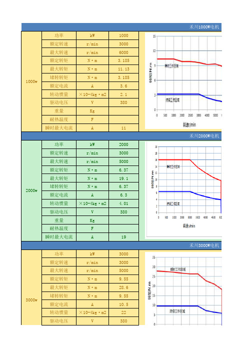
功率kW 1000额定转速r/min3000最大转速r/min6000额定转矩N·m 3.185最大转矩N·m11.13堵转转矩N·m 3.185额定电流A 3.6转动惯量×10-4kg·m2 2.1驱动电压V380
重量Kg
耐热温度F
瞬时最大电流A11
功率kW2000额定转速r/min3000最大转速r/min5000额定转矩N·m 6.37最大转矩N·m19.1堵转转矩N·m 6.37额定电流A 6.3转动惯量×10-4kg·m2 4.01驱动电压V380
重量Kg
耐热温度F
瞬时最大电流A19
功率kW3000额定转速r/min3000最大转速r/min5000额定转矩N·m9.55最大转矩N·m28.6堵转转矩N·m9.55额定电流A10.5转动惯量×10-4kg·m222驱动电压V380禾川1000W电机
3000w 禾川2000W电机
1000w
2000w
禾川3000W电机
重量Kg
耐热温度F
瞬时最大电流A32
功率kW5000额定转速r/min2000最大转速r/min4000额定转矩N·m23.9最大转矩N·m71.6堵转转矩N·m31额定电流A21转动惯量×10-4kg·m2166.6驱动电压V380
重量Kg
耐热温度F
瞬时最大电流A70禾川5000W电机
5000w。
海特克柱塞马达样本-HA6V
产品外观及简介
开式回路和闭式回路 规格8 0、10 7、1 6 0 高压范 围 至3 5 M P a
目录
特点…………………………………………………………………………………………………………………………… 147 剖视图………………………………………………………………………………………………………………………… 147 型号说明……………………………………………………………………………………………………………………… 148 技术参数……………………………………………………………………………………………………………………… 149 HD液控 变 量 … … … …… … … … … … … … … … … … ………………………………………………………………………… 150 HA高压 自 动 变 量 … …… … … … … … … … … … … … ………………………………………………………………………… 151 外形尺寸……………………………………………………………………………………………………………………… 152
规格的计算
流量
qv
=
V g·n· ηv —
1000
[L / m i n]
输出转速
N
=
Q·1 0 0 0·ηv —
Vg
[r / m i n]
输出扭矩
M
=
— V g· △p·ηmh
=
1 . 5 9 V g· △p·ηmh —
[N
m]
2π
10
或 M =— K M· △P·ηmh 10
[N m]
输出功率
P=
控 制 起 点 在V gmin 控 制 终 点 在V gmax。
爱森 Moeller 系列 PKZM0 电机保护断路器 产品说明说明书
Eaton 039427Eaton Moeller® series PKZM0 Motor-protective circuit-breaker, 3p+1N/O+1N/C, Ir=1.6-2.5A, screw connectionGeneral specificationsEaton Moeller® series PKZM0 Motor-protective circuit-breaker039427401508039427376 mm 93 mm 54 mm 0.326 kgIEC/EN 60947-4-1 VDE 0660CSA-C22.2 No. 60947-4-1-14 UL CE CSAUL Category Control No.: NLRV CSA Class No.: 3211-05 UL 60947-4-1 UL File No.: E36332 IEC/EN 60947 CSA File No.: 165628 UL CSAProduct NameCatalog Number EANProduct Length/Depth Product Height Product Width Product Weight CertificationsTurn buttonPhase-failure sensitivity (according to IEC/EN 60947-4-1, VDE 0660 Part 102)Auxiliary switchMotor protectionPhase failure sensitiveThree-pole ATEX dust-ex-protection, PTB 10, ATEX 3013, Ex II(2) GD100,000 operations100,000 OperationsCan be snapped on to IEC/EN 60715 top-hat rail with 7.5 or15 mm height.40 Operations/hIII3Motor protective circuit breakerFinger and back-of-hand proof, Protection against direct contact when actuated from front (EN 50274)6000 V AC25 g, Mechanical, according to IEC/EN 60068-2-27, Half-sinusoidal shock 10 msBranch circuit: Manual type E if used with terminal, or suitable for group installations, (UL/CSA)Also motors with efficiency class IE3≤ 0.25 %/K, residual error for T > 40°-5 - 40 °C to IEC/EN 60947, VDE 0660-25 - 55 °C, Operating rangeActuator type FeaturesFitted with: Functions Number of poles Explosion safety category for dust Lifespan, electricalLifespan, mechanicalMounting positionOperating frequencyOvervoltage categoryPollution degreeProduct categoryProtectionRated impulse withstand voltage (Uimp) Shock resistanceSuitable forTemperature compensationAltitude Terminal capacity (flexible with ferrule)Max. 2000 m-25 °C55 °C25 °C40 °C40 °C80 °CDamp heat, cyclic, to IEC 60068-2-30 Damp heat, constant, to IEC 60068-2-781 x (0.75 - 1.5) mm²2 x (0.75 - 1.5) mm²1 x (0.75 - 2.5) mm², Control circuit cables2 x (0.75 - 2.5) mm², Control circuit cables18 - 1018 - 1410 mm1 Nm, Screw terminals, Control circuit cables 1.7 Nm, Screw terminals, Main cable50 Hz60 Hz2.5 A0.37 kW0.75 kW690 V690 V2.5 A60 kA DC, up to 250 V DC, Main conducting paths 65 kA, 480 Y/277 V, SCCR (UL/CSA) 0.5 HP 0.17 HPAmbient operating temperature - minAmbient operating temperature - maxAmbient operating temperature (enclosed) - min Ambient operating temperature (enclosed) - max Ambient storage temperature - minAmbient storage temperature - maxClimatic proofing Terminal capacity (solid)Terminal capacity (solid/stranded AWG)Stripping length (main cable)Tightening torqueRated frequency - minRated frequency - maxRated operational current (Ie)Rated operational power at AC-3, 220/230 V, 50 Hz Rated operational power at AC-3, 380/400 V, 50 Hz Rated operational voltage (Ue) - minRated operational voltage (Ue) - maxRated uninterrupted current (Iu)Short-circuit currentShort-circuit current rating (type E)Assigned motor power at 200/208 V, 60 Hz, 3-phase Assigned motor power at 230/240 V, 60 Hz, 1-phaseAccessories required BK25/3-PKZ0-E65 kA, 240 V, SCCR (UL/CSA)50 kA, 600 Y/347 V, SCCR (UL/CSA)± 20% tolerance, Trip blocks38.8 A, Irm, Setting range max.Basic device fixed 15.5 x Iu, Trip Blocks 0.5 HP1 HP 1.5 HPScrew terminals 1.6 A2.5 AOverload trigger: tripping class 10 A5.16 W0 W1.72 W2.5 A0 WMeets the product standard's requirements. Meets the product standard's requirements. Meets the product standard's requirements. Meets the product standard's requirements.Motor Starters in System xStart - brochureSave time and space thanks to the new link module PKZM0-XDM32MEProduct Range Catalog Switching and protecting motorsSwitching and protecting motors - catalogeaton-manual-motor-starters-characteristic-characteristic-curve-008.eps eaton-manual-motor-starters-characteristic-characteristic-curve-009.eps eaton-manual-motor-starters-characteristic-characteristic-curve-010.epsDA-DC-00004921.pdfDA-DC-00004892.pdfeaton-manual-motor-starters-pkz-dimensions-003.epseaton-manual-motor-starters-pkz-dimensions.epseaton-manual-motor-starters-pkz-dimensions-002.epseaton-manual-motor-starters-pkzm0-3d-drawing-008.epseaton-manual-motor-starters-mounting-3d-drawing-002.epseaton-general-ie-ready-dilm-contactor-standards.epsShort-circuit release Assigned motor power at 230/240 V, 60 Hz, 3-phase Assigned motor power at 460/480 V, 60 Hz, 3-phase Assigned motor power at 575/600 V, 60 Hz, 3-phaseConnection Overload release current setting - minOverload release current setting - maxTripping characteristicEquipment heat dissipation, current-dependent PvidHeat dissipation capacity PdissHeat dissipation per pole, current-dependent PvidRated operational current for specified heat dissipation (In) Static heat dissipation, non-current-dependent Pvs10.2.2 Corrosion resistance10.2.3.1 Verification of thermal stability of enclosures10.2.3.2 Verification of resistance of insulating materials to normal heat10.2.3.3 Resist. of insul. mat. to abnormal heat/fire by internal elect. effects BrochuresCatalogues Characteristic curve Declarations of conformity DrawingsMeets the product standard's requirements.Does not apply, since the entire switchgear needs to be evaluated.Does not apply, since the entire switchgear needs to be evaluated.Meets the product standard's requirements.Does not apply, since the entire switchgear needs to be evaluated.Meets the product standard's requirements.Does not apply, since the entire switchgear needs to be evaluated.Does not apply, since the entire switchgear needs to be evaluated.Is the panel builder's responsibility.Is the panel builder's responsibility.Is the panel builder's responsibility.Is the panel builder's responsibility.Is the panel builder's responsibility.The panel builder is responsible for the temperature rise calculation. Eaton will provide heat dissipation data for the devices.Is the panel builder's responsibility. The specifications for the switchgear must be observed.eaton-manual-motor-starters-circuit-breaker-pkzm0-3d-drawing.epsDA-CE-ETN.PKZM0-2,5_NHI11IL03407011ZIL03402034ZWIN-WIN with push-in technologyeaton-motor-protective-circuit-breaker-pkzm0-overload-monitoring-exe-manual-mn03402003z-de-de-en-us.pdfIL122023ZUDA-CS-pkzm0_nhi11DA-CD-pkzm0_nhi1110.2.4 Resistance to ultra-violet (UV) radiation10.2.5 Lifting10.2.6 Mechanical impact10.2.7 Inscriptions10.3 Degree of protection of assemblies10.4 Clearances and creepage distances10.5 Protection against electric shock10.6 Incorporation of switching devices and components 10.7 Internal electrical circuits and connections10.8 Connections for external conductors10.9.2 Power-frequency electric strength10.9.3 Impulse withstand voltage10.9.4 Testing of enclosures made of insulating material 10.10 Temperature rise10.11 Short-circuit rating10.12 Electromagnetic compatibility eCAD model Installation instructions Installation videos Manuals and user guides mCAD modelEaton Corporation plc Eaton House30 Pembroke Road Dublin 4, Ireland © 2023 Eaton. All rights reserved. Eaton is a registered trademark.All other trademarks areproperty of their respectiveowners./socialmediaIs the panel builder's responsibility. The specifications for the switchgear must be observed.The device meets the requirements, provided the information in the instruction leaflet (IL) is observed.10.13 Mechanical function。
纳美电机产品简介说明书
SINGLE PHASE, 56C FRAME, TEFC1/3 HP—2 HP; 2 or 4-Pole High Starting TorquesCapacitor Start / Capacitor Run Design Rolled Steel Construction Removable FeetSINGLE PHASE, COMPRESSOR DUTY, ODP3 HP–5 HP; 2 or 4-Pole High Starting TorqueCapacitor Start / Capacitor Run Design Rolled Steel ConstructionTHREE -PHASE, 56C FRAME, TEFC1/3 HP—3 HP; 2 or 4-Pole High Starting Torque Rolled Steel Construction Removable FeetTHREE -PHASE, TEFC1 HP—10 HP;2 or 4-Pole High Starting Torque Rolled Steel ConstructionTHREE -PHASE, OPEN DRIP PROOF1 HP—20 HP;2 or 4-Pole High Starting Torque Rolled Steel ConstructionWASHDOWN DUTY MOTORS STAINLESS STEEL1/3 HP—20 HP; 2, 4 or 6-Pole C -Flange w/ Feet or Round Body Inverter Duty (20:1 VT; 10:1 CT)CLOSE COUPLED PUMP MOTORS1 HP—75 HP;2 or 4-Pole Totally Enclosed Fan Cooled Inverter Duty (20:1 VT; 10:1 CT)EXPLOSION PROOF MOTORS1—250 HP; 2, 4 or 6-PoleAll Motors Meet or Exceed UL 674 SpecificationAs Required By OSHA For Installation and Use In Hazardous LocationsTotally Enclosed Explosion Proof (TEXP) Inverter Rated (10:1 VT; 5:1 CT)OIL WELL PUMP MOTORS, TEFC2 HP—150 HP; 6 or 8-PoleNEMA Design D; High Slip (5%—8% Slip) Special Purpose Oil Well Pump Motors Inverter Duty (20:1 VT; 10:1 CT)OIL WELL PUMP MOTORS, ODP7.5 HP—100 HP; 6-PoleNEMA Design D; High Slip (5%—8% Slip) Special Purpose Oil Well Pump Motors Inverter Duty (20:1 VT; 10:1 CT)VERTICAL HOLLOW SHAFT PUMP MOTORS10 HP—500 HP; 4-PoleExtra High Thrust / Double Stacked Bearings AvailableInverter Rated (10:1 VT) or Inverter Duty (20:1 VT)ROTARY UNIT MOTOR FOR ROTARY PHASE CONVERTER3 HP—60 HP; 4-PoleFor Use with Rotary Phase Converters To Run Three Phase Equipment From Single Phase PowerTotally Enclosed Fan CooledSHAFT MOUNT REDUCERS & ACCESSORIES2—10 Box SizeGear Ratios: 15:1 or 25:1Screw Conveyor Adaptors Available Repair Kits Also AvailableCONTROLS:Safety/Disconnect Switches Across the Line Starters (ATL) Part Wind Starters (PWS) Soft StartersVFDs (Available in NEMA 3R, 4, 4X and 12)MOTOR SLIDE BASESAvailable 56—505U FrameSingle -Adjusting Screw Type (56—145T Frame) Double -Adjusting Screw Type (182T—505U Frame)GENERAL PURPOSEINVERTER DUTY MOTORS1 HP—300 HP; 2, 4, 6 or 8-Pole NEMA Design BTotally Enclosed Fan Cooled or Open Drip ProofInverter Duty (20:1 VT; 10:1 CT)ALUMINUM FRAMEINVERTER DUTY MOTORS1 HP—10 HP;2 or 4-Pole Totally Enclosed Fan Cooled Inverter Duty (20:1 VT; 10:1 CT)SINGLE PHASE, FARM DUTY, TEFC1/3 HP—10 HP; 2 or 4-Pole High Starting TorquesManual Overload Protection (1/3 HP—5 HP) Capacitor Start / Capacitor Run Design Rolled Steel ConstructionCRUSHER DUTY MOTORS1 HP—600 HP; 4, 6 or 8-Pole NEMA Design CTotally Enclosed Fan CooledInverter Duty (20:1 VT; 10:1 CT) (1 HP—300 HP) Inverter Rated (10:1 VT; 5:1 CT) (250 HP—600 HP)ROUND BODY MOTORS1 HP—30 HP; 4-Pole; 1800 RPM C -Flange without FeetTotally Enclosed Fan Cooled Inverter Duty (20:1 VT; 10:1 CT)SAFETY SWITCHES – HEAVY DUTY30 AMP—1200 AMP 480 VAC / 600 VAC3-Pole / 3-Wire / Non -Fused or Fused NEMA 3R EnclosureVFD–ECONOMY1 HP—800 HP Variable Torque ½ HP—600 HP Constant Torque Siemens Series DriveNon -Combo, Circuit Breaker or Fused NEMA 3R, 4, 4X or 12 EnclosureSOFT STARTERS–CRUSHER/ULTRA20 HP—800 HPSAF MS6 Series DevicesUltra Heavy Duty (500% FLA for 30 Seconds) Full Start -Rated ContactorCircuit Breaker w/ Through Door NEMA 3R or 4/12 EnclosureSOFT STARTERS15 HP—300 HPSiemens 3RW40 Series Device Normal Duty or Heavy Duty Non -Combo or Circuit Breaker NEMA 3R, 4X or 4/12 EnclosurePART WIND STARTERS10 HP—200 HPIEC Rated Contactors Circuit Breaker or Fused NEMA 3R EnclosureACROSS THE LINE START-ERSNEMA 1—NEMA 5NEMA Full Rated ContactorCircuit Breaker or Fused w/ FlangedVFD–STANDARD1 HP—800 HP Variable Torque ½ HP—600 HP Constant Torque Siemens Series Drive Circuit Breaker or FusedNEMA 3R, 4, 4X or 12 EnclosureVFD–POSITIVE DISPLACEMENT PUMP3 HP—600 HPSiemens Series Drive Constant TorqueCircuit Breaker w/ Flanged NEMA 3R EnclosureVFD–IRRIGATION1 HP—800 HPSiemens Series Drive24/7 Programmable & 0—10 Backspin Timer Variable TorqueCircuit Breaker or Fused NEMA 3R EnclosureVFD–SUBMERSIBLE½ HP—200 HPSiemens Series Drive24/7 Programmable & 0—10 Backspin Timer Variable TorqueCircuit Breaker or Fused NEMA 3R EnclosureVFD–WASHDOWN/STAINLESS1 HP—200 HP Variable Torque ½ HP—150 HP Constant Torque Siemens Series Drive Circuit Breaker or Fused NEMA 4X EnclosureVFD–BEAM PUMP1 HP—200 HPSiemens Series Drive ReGen Avoidance Design Constant TorqueCircuit Breaker w/ Flanged NEMA 3R EnclosureCUSTOM PANELSMotor Controls Panel Customization Made EasyNAE Motor Controls offers customers the ability to custom configure and order their control panel to meet their specific needs and have it shipped quickly. All NAE packaged panels are backed by our 2 year warranty and eligible for up to 6 years of protection with the “NO Hassle ” Chassis Exchange program.NO Hassel Bumper to Bumper Chassis Exchange ProgramOptional three (3) year Warranty with Lightning & Surge Protection including NAE ’s “No Hassel ” Chassis Exchange program.Scan or visit our website at to learn more.。
MAXON 电机完全手册(全系列)_MAXON MOTOR 完全手册1
PDF 文件使用 "pdfFactory Pro" 试用版本创建
PDF 文件使用 "pdfFactory Pro" 试用版本创建
PDF 文件使用 "pdfFactory Pro" 试用版本创建
PDF 文件使用 "pdfFactory Pro" 试用版本创建
PDF 文件使用 "pdfFactory Pro" 试用版本创建
PDF 文件使用 "pdfFactory Pro" 试用版本创建
PDF 文件使用 "pdfFactory Pro" 试用版本创建
PDF 文件使用 "pdfFactory Pro" 试用版本创建
PDF 文件使用 "pdfFactory Pro" 试用版本创建
PDF 文件使用 "pdfFactory Pro" 试用版本创建
PDF 文件使用 "pdfFactory Pro" 试用版本创建
PDF 文件使用 "pdfFactory Pro" 试用版本创建
PDF 文件使用 "pdfFactory Pro" 试用版本创建
PDF 文件使用 "pdfFactory Pro" 试用版本创建
PDF 文件使用 "pdfFactory Pro" 试用版本创建
PDF 文件使用 "pdfFactory Pro" 试用版本创建
PDF 文件使用 "pdfFactory Pro" 试用版本创建