Design For Manufacturing- level I
Design for Manufacturing and Assembly

Design for Manufacturing and Assembly Design for Manufacturing and Assembly (DFMA) is a process that involves designing a product with the aim of ensuring that it can be manufactured and assembled easily, efficiently, and cost-effectively. The DFMA process is critical to the success of any product development project. It is essential to consider DFMA early in the design process to minimize the cost of production and ensurethat the product meets the required quality standards. This article will explore the importance of DFMA and how it can be implemented in product design.DFMA is essential in product design because it helps to reduce the cost of production. By designing a product that is easy to manufacture and assemble, the cost of production is significantly reduced. When a product is designed with manufacturing and assembly in mind, it is easier to identify potential issues that could increase the cost of production. For instance, if a product has complex parts that are difficult to manufacture, it will take more time and effort to produce, which will increase the cost of production. By designing a product that is easy to manufacture and assemble, the cost of production is minimized, and the product becomes more affordable to consumers.Another important aspect of DFMA is that it helps to improve product quality. When a product is designed with manufacturing and assembly in mind, it is easier to identify potential quality issues. For instance, if a product has parts that are difficult to assemble, there is a higher likelihood that the product will have defects. By designing a product that is easy to assemble, the likelihood of defects is reduced, and the product quality is improved. This, in turn, enhances customer satisfaction and loyalty.DFMA also helps to reduce the time it takes to bring a product to market. When a product is designed with manufacturing and assembly in mind, the time it takes to produce the product is significantly reduced. This is because the product is designed in a way that makes it easy to manufacture and assemble. As a result, the product can be produced quickly, and it can be brought to market faster. This is critical in today's fast-paced business environment, where time-to-market is a critical success factor.Incorporating DFMA into product design requires a collaborative effort between the design team and the manufacturing team. The design team needs to work closely with the manufacturing team to ensure that the product is designed in a way that makes it easy to manufacture and assemble. The manufacturing team, on the other hand, needs to provide feedback to the design team on the manufacturability and assembly of the product. This feedback is critical in identifying potential issues and making necessary design changes.In conclusion, DFMA is an essential process in product design. It helps to reduce the cost of production, improve product quality, and reduce time-to-market. Incorporating DFMA into product design requires a collaborative effort between the design team and the manufacturing team. By designing a product that is easy to manufacture and assemble, the product becomes more affordable to consumers, and customer satisfaction and loyalty are enhanced. Therefore, it is critical to consider DFMA early in the design process to ensure that the product meets the required quality standards and is cost-effective to produce.。
manufacturing readiness level -回复

manufacturing readiness level -回复什么是制造成熟度水平(Manufacturing Readiness Level,简称MRL)?制造成熟度水平(MRL)是评估和衡量新产品或技术在制造方面准备就绪程度的一种工具。
它是由美国国防部开发的,旨在帮助制造业界评估和提升技术和产品的制造成熟度。
通过使用MRL,制造商可以在产品开发过程的各个阶段中了解到产品或技术的制造准备情况,以及关键制造能力的不足之处。
MRL是由九个不同的等级组成,从1级到9级,级别越高,代表产品或技术的制造成熟度越高。
以下将逐级详细介绍每个级别:1级:研究开发阶段(Basic Research)在1级,产品或技术的基础研究正在进行中,还没有进入实际制造的阶段。
该等级的评估目的是确定技术选择的可行性,并开始进行初步的科学研究。
2级:技术概念证明(Technology Concept)在2级,初步的概念验证已经完成,技术方案的可行性经过了初步分析。
这个阶段通常涉及到模型的建立、实验室测试和理论验证。
3级:实验室验证(Laboratory Validation)在3级,技术方案的实验室验证已经完成,初步的技术参数和性能指标得到了验证。
这个阶段通常会使用不完全的设备和材料进行测试,以确定技术在实践中的可行性。
4级:实验室验证(Laboratory Validation)在4级,技术方案的实验室验证已经完成,产品或技术的性能参数已经评估。
这个阶段通常会使用逼真的设备和原材料进行测试,以验证技术在实际操作中的稳定性和可控性。
5级:组件验证(Component Validation)在5级,关键部件和元件的验证已经完成。
这个阶段涉及到在现实环境中测试和验证零部件的性能参数,以确保它们能够满足产品的整体需求。
6级:系统验证(System Validation)在6级,整个系统的验证已经完成。
这个阶段涉及到在实际环境中测试和验证整个系统的性能参数,以确保它能够满足产品的需求和规格。
DFM概述

两Via孔距离太 近,可能造成渗 镀,微short
Via孔的孔环太 小,可能使该 via孔破
Pad与PTH/ NPTH 孔重叠,造成该pad 被孔钻掉
Via孔与PTH孔距 离太近,可能造成 渗镀,微short
21
Via 孔的防焊层只开 部分,将导致该via 內进绿漆,造成拒焊
DFM的优点
企业追求目标: 低成本、高产出、良好的供货能力。长期高可靠性的
空接线,该线段无 实际作用
solder mask与外层 pad的annular ring距 离太近
加大etch shrink值之后 所产生的一些碎铜
20
因两区域间的导通距离只
有1.8mil, 故放大etch shrink值后, 即造成两区域
HDI Microvia (HDI盲埋孔分析)
Via 孔的防焊层只开 部分,將导致该via 內进绿漆,造成拒焊
《 可制造性设计DFM》
Dr. Pan kailin E-mail: pankl@
DFM、DFR、DFx介绍
• DFM: Design for Manufacturing 可制造性设计
• DFT: Design for Test
可测试性设计
• DFD: Design for Diagnosibility 可分析性设计
Dr. Pan kailin E-mail: pankl@
电子组装的现状与趋势
绿色制造(重点是无铅、无卤素); 更小、更薄、更复杂与高密度; 设计与制造分离,设计验证与工艺验证成本
高、周期长; 混合装配
– 插装与表贴混装 – 无铅与有铅混装 (兼容性问题突出) 从批量上看,多品种、小批量
测试点和测试点靠太近, 造成测试时的干涉
Design for X

DFM Method
Proposed Design
Estimate the Manufacutring Costs
Reduce the Costs of Components
N Good enough ? Y
Acceptable Design
DFM Method
• Estimate the manufacturing costs. • Reduce the costs of components. • Reduce the costs of assembly. • Reduce the costs of supporting production. • Consider the impact of DFM decisions on
Elements of the Manufacturing Cost of a Product
Manufacturing Cost
Components
Standard
Custom
Raw Material
Processing
Assembly
Labor
Equipment and Tooling
Tooling
Gathering DFM Information
• Sketches, drawings, product specifications, and design alternatives.
• A detailed understanding of production and assembly processes
IEEE Xplore Full-Text PDF_
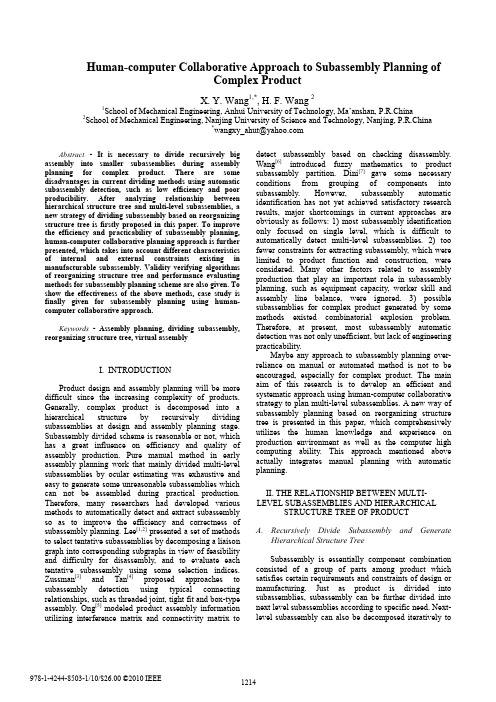
Abstract - It is necessary to divide recursively big assembly into smaller subassemblies during assembly planning for complex product. There are some disadvantages in current dividing methods using automatic subassembly detection, such as low efficiency and poor producibility. After analyzing relationship between hierarchical structure tree and multi-level subassemblies, a new strategy of dividing subassembly based on reorganizing structure tree is firstly proposed in this paper. To improve the efficiency and practicability of subassembly planning, human-computer collaborative planning approach is further presented, which takes into account different characteristicsof internal and external constraints existing in manufacturable subassembly. Validity verifying algorithmsof reorganizing structure tree and performance evaluating methods for subassembly planning scheme are also given. To show the effectiveness of the above methods, case study is finally given for subassembly planning using human-computer collaborative approach.Keywords - Assembly planning, dividing subassembly, reorganizing structure tree, virtual assemblyI. INTRODUCTIONProduct design and assembly planning will be more difficult since the increasing complexity of products. Generally, complex product is decomposed into a hierarchical structure by recursively dividing subassemblies at design and assembly planning stage. Subassembly divided scheme is reasonable or not, which has a great influence on efficiency and quality of assembly production. Pure manual method in early assembly planning work that mainly divided multi-level subassemblies by ocular estimating was exhaustive and easy to generate some unreasonable subassemblies which can not be assembled during practical production. Therefore, many researchers had developed various methods to automatically detect and extract subassembly so as to improve the efficiency and correctness of subassembly planning. Lee[1,2] presented a set of methodsto select tentative subassemblies by decomposing a liaison graph into corresponding subgraphs in view of feasibility and difficulty for disassembly, and to evaluate each tentative subassembly using some selection indices. Zussman[3] and Tan[4] proposed approaches to subassembly detection using typical connecting relationships, such as threaded joint, tight fit and box-type assembly. Ong[5] modeled product assembly information utilizing interference matrix and connectivity matrix to detect subassembly based on checking disassembly. Wang[6] introduced fuzzy mathematics to product subassembly partition. Dini[7] gave some necessary conditions from grouping of components into subassembly. However, subassembly automatic identification has not yet achieved satisfactory research results, major shortcomings in current approaches are obviously as follows: 1) most subassembly identification only focused on single level, which is difficult to automatically detect multi-level subassemblies. 2) too fewer constraints for extracting subassembly, which were limited to product function and construction, were considered. Many other factors related to assembly production that play an important role in subassembly planning, such as equipment capacity, worker skill and assembly line balance, were ignored. 3) possible subassemblies for complex product generated by some methods existed combinatorial explosion problem. Therefore, at present, most subassembly automatic detection was not only unefficient, but lack of engineering practicability.Maybe any approach to subassembly planning over-reliance on manual or automated method is not to be encouraged, especially for complex product. The main aim of this research is to develop an efficient and systematic approach using human-computer collaborative strategy to plan multi-level subassemblies. A new way of subassembly planning based on reorganizing structure tree is presented in this paper, which comprehensively utilizes the human knowledge and experience on production environment as well as the computer high computing ability. This approach mentioned above actually integrates manual planning with automatic planning.II. THE RELATIONSHIP BETWEEN MULTI-LEVEL SUBASSEMBLIES AND HIERARCHICALSTRUCTURE TREE OF PRODUCTA.Recursively Divide Subassembly and GenerateHierarchical Structure TreeSubassembly is essentially component combination consisted of a group of parts among product which satisfies certain requirements and constraints of design or manufacturing. Just as product is divided into subassemblies, subassembly can be further divided into next level subassemblies according to specific need. Next-level subassembly can also be decomposed iteratively toHuman-computer Collaborative Approach to Subassembly Planning ofComplex ProductX. Y. Wang1,*, H. F. Wang 21School of Mechanical Engineering, Anhui University of Technology, Ma’anshan, P.R.China2School of Mechanical Engineering, Nanjing University of Science and Technology, Nanjing, P.R.China*wangxy_ahut@lower level subassemblies until the granularity meets the engineering requirements. Product structure hierarchy is finally generated due to all the parent-child relationships between both assembly units that may be subassembly or part type. Structure tree shown in Fig.1 is actually a graph expression of structure hierarchy, on which leaf node represents part, intermediate node denotes subassembly. The distribution of intermediate nodes on structure tree maps to divided scheme of various level subassemblies. When subassembly division is changed, the members of corresponding intermediate node are surely modified. On the other hand, adjusting the members of certain intermediate node implies altering the construction of corresponding subassembly.During digital product assembly, engineer firstly preassembly various-level subassemblies to get entire assembly model information, including primary structure tree of product. Specifically, at the beginning of product preassembly, it is difficult for engineer to considerate thoughtfully all constraints and only once be able to get an accurate and reasonable divided scheme of subassembly for manufacturing. To modify those unreasonable subassemblies, engineer can adjust the members of corresponding intermediate node on structure tree in digital system by some interactive means, such as transfer, add and delete node. The modifying method mentioned above is actually to redivide and replan subassembly by reorganizing structure tree (shown inFig.2). Obviously, digital system should also provide some reasonableness analysis for new planned subassemblies. Some algorithms of verifying reasonable subassembly will be introduced in the following sections.B. Necessary Conditions From Grouping of Parts IntoSubassembly for ManufacturingSubassembly divided schemes of product maybe are different at different development stages. During the design process, the factors that drive grouping of parts into subassembly usually depend on subsystem function implement, design task assign, subsystem outsourcing supplier and so on, which often ignore the assembly feasibility of subassembly in the future manufacturing [8]. However, at the stage of assembly planning, subassembly divided scheme must satisfy at least two hard constraints so as to execute feasibly the future manufacturing, namely spatial adjacency and non-obstruction. The two constraints are also necessary conditions from grouping of parts into subassembly for manufacturing.Spatial adjacency constraint indicates that there must be direct or indirect mate relationship between arbitrary both parts in subassembly, otherwise the subassembly would be spontaneously disassembled. Non-obstruction constraint requests subassembly to be collision-free for the other parts being assembled. Spatial adjacency of subassembly is verified by checking connectivity of mate relationship graph in this paper, which is an improved method based on traditional way in [7]. Non-obstruction of subassembly is verified using compressed interference matrix relative to its parent assembly that was also presented in [7].III. MULTI-LEVEL SUBASSEMBLIES PLANNING BASED ON HUMAN-COMPUTERCOLLABORATIVE STRATEGYSince the complexity of product and the diversity of manufacturing environment, there are many constrain conditions to subassembly division during assembly planning. These conditions are classified into two types: inner hard constraint and external soft constraint. Inner hard constraint is actually the requirements of geometric feasibility and derived from product construction, which includes spatial adjacency and non-obstruction. If hard constraint just relied on manual visual estimation, poor accuracy and low efficiency would be inevitable. Some verification algorithms introduced in the previous section are used and rapidly performed by computer to avoid the above disadvantages. External soft constraint mainly refers to some requirements resulted from manufacturing environment, such as assembly equipment capability, worker skill, production rhythm, etc. These soft constraints are often uncertain and it is difficult for most of them to be expressed quantitatively. To efficiently plan subassembly of complex product, a human-computer collaborative approach is used, in which hard and soft constraint are respectively dealt with by computer andFig.2. Reorganizing structure tree and redividing subassemblyOriginal structure treeNew structure treeSubassembly / imermediate node Part / leaf nodeFig.1. Multi-level subassemblies and hierarchical structure treeProduct assembly / root nodeengineer. There are three main stages in this approach (shown in Fig.3): reorganizing structure tree, verifying geometric feasibility and evaluating overall scheme.At the first stage, reorganizing operation to structure tree is performed by engineer in digital assembly system with interactive visualization interface. After considering some soft constraints, including product construction, manufacturing resource and production environment, the engineer can adjust structure tree by adding, transferring and deleting node on the tree to redefine the members of subassembly. During the reorganizing process, engineer can also search heuristic knowledge database of assembly process and observe 3-D product model to help him make decision. Digital assembly system checks reorganizing action in real time to prevent invalid and illegal operation.At the second stage ,assembly system verifies geometric feasibility(hard constraint) for every redefined subassembly according to verifying algorithms. Finally, the overall performance of subassembly scheme is evaluated to provide engineer some analytical data.On the other hand, some assembly information would change as structure tree reorganized. Assembly system must be able to provide dynamic management service to maintain the consistency, integrality and correctness of assembly model during reorganizing structure tree.IV. VALIDITY VERIFICATION FOR REORGANIZATION AND PERFORMANCE EVALUATION FOR SUBASSEMBLY SCHEMEIt is inevitable for engineer to make some mistakes during reorganizing structure tree by human-computer interaction, for which some subassemblies maybe would be unable to be assembled in the future manufacturing. Digital assembly system should verify engineering validity for reorganization. The flow of verifying validity shown in Fig.3 has two main processes: 1) detect validity of reorganizing action, 2) verify geometry feasibility.A. Validity Detecting Method for Reorganizing ActionValidity detecting for reorganizing action is to check engineer if he performs invalid operation that violates the basic rules. These rules are as follows:Rule 1: when add A node as child of B node, if B was leaf type node then adding operation is invalid.Rule 2: when transfer A node as child of B node, if B was leaf type node then transferring operation is invalid.Rule 3: when transfer A node as child of B node, if B was a descendant of A node then transferring operation is invalid.Fig.3. Human-computer collaborative planning for manufacturable subassemblyRule 4: when delete A node, if A had at least one child node or A was leaf type node then deleting operation is invalid.The above four nonsensical action are respectively shown in Fig.4 by ①,②,③ and ④. If reorganizing operation violated the rules mentioned above, assembly system would warn engineer the action errors.B. Verifying Method for Geometry Feasibility ofSubassemblyAfter passing reorganizing action check, subassembly implied on structure tree is only possible subassembly. If possible subassembly changed into feasible subassembly for manufacturing, it must satisfy two hard constraint conditions mentioned in the above section: spatial adjacency in itself and non-obstruction for other parts. 1) Verifying Method for Spatial AdjacencyAll mate relationships between both next-level units among subassembly were represented by an undirected graph, in which node denotes assembly unit and edge represents mate relationship. If this graph was connected, the subassembly could pass the verification for spatial adjacency, otherwise digital assembly system would search all connected subgraphs and advise engineer to modify further the subassembly members with some suggestions generated by those subgraphs. 2) Verifying Method for non-obstructionTo detect possible subassembly if it interferes its brother-node type part to be assembled, the verifying procedures is as following.Step1: get the interference matrix of the subassembly and that of its parent assembly.Step2: calculate the compressed interference matrix about the parent assembly relative to the subassembly.Step3: search corresponding parts in compressed interference matrix which all directions do not have degree of freedom of movement. If the corresponding part does not exist, the subassembly is collision-free for the other parts to be assembled, otherwise those corresponding parts could not be assembled to expected position since this subassembly obstruction, and verifying process turns to next step.Step4: search parent assembly of every corresponding part.If assembly system detected the obstruction of possible subassembly, it would be able to show engineerdetailed information generated in step4, by which engineer could be guided to next correct reorganization.Verifying spatial adjacency is relatively simple and computing time is less, so the sequence of verifying geometry feasibility is firstly to verify spatial adjacency, then to verify non-obstruction, which can prevent complex and exhausting computation for subassembly not pass spatial adjacency verification to avoid meaningless verification.C. Performance Evaluation to Overall Scheme ofSubassembly PlanningTwo factors are considered to evaluate the manufacturing performance of the overall planned result (namely new structure tree).1) Parallelity of whole assemblyParl(P )= n /m (1)where P denotes whole product, n is the number of parts of P and m denotes the number of subassemblies on structure tree. The smaller Parl (P ) value is, the better production parallelity of overall subassembly scheme can be gotten.2) Stability of overall subassemblywhere S i denotes the i th subassembly, P and m represent the same meanings as formula (1). Stab(S ) indicates the stability of single subassembly S , which is calculated by degree of separation freedom of subassembly introduced in [9].V. CASE TESTWe have conducted several assembly cases to test and verify the subassembly planning approach described above in DPAS (Digital Preassembly System) developed by our research group. Part model constructed in commerce CAD system can be assembled in DPAS by exporting mediate format [10]. Here a small universal transmission device is taken as case test.The universal transmission machine had been decomposed into three main subassembly system (shown in Fig.5) at preassembly stage. However, some ofFig.5. Original structure tree of machineB(on second level)A(on second level) mS P mi i /)Stab()Stab(1∑==(2)Transfer node Add new node Delete nodeFig.4. Invalid operation actionPart node Subassembly nodesubassemblies could not actually be assembled in the future production because it is difficult for engineer to considerate all hard and soft constraints about manufacturing. For example, left bracket subsystem and right bracket subsystem had same rotating function and were designed in the same subassembly—pitching system. They are not adjacent in this case, so pitching system would be unable to be assembled at manufacturing stage. According to manufacturing requirements, engineer can modify those unreasonable subassemblies by reorganizing original structure tree. DPAS checks reorganizing action in real time during reorganization and gives some warning information about invalid operation. Verifying module of geometry feasibility in DPAS can been enable by engineer to verify the producibility of subassembly. If a subassemlby did not pass verification of geometry feasibility, the DPAS would give detailed analysis report for engineer to help him correctly replan subassembly. Reorganized result is partly shown in Fig.6, which actually is new structure tree of universal transmission device for manufacturing. Comparing between Fig.5 and Fig.6, we could find that left and right bracket subassembly had been transferred from second level to first level, a new subassembly called left bracket subcomponents had been created.During the reorganizing process, engineer could conveniently plan subassembly by drawing tree node andobserving timely new subassembly in visualization. At the same time, digital assembly system automatically manage and maintain the change of assembly model informationresulted from reorganizing structure tree[11].VI. CONCLUSIONReasonable division of multi-level subassemblies for complex product has always been one of difficult problems existing in assembly planning. A new human-computer collaborative method is presented to improve the efficiency and manufacturability of subassemblyplanning in this paper, which has the followingcharacteristics:1) Take reorganizing structure tree as important means of subassmebly planning. The relationship between multi-level subassemblies and structure tree is inverselyused in this method. The aim of reorganizing structure tree is to generate more reasonable subassembly.2) Utilize human-computer collaborative strategy to guarantee the efficiency and practicability of subassembly planning. During subassembly planning, the soft contraints related to manufacturing are considered by engineer and the hard constraints are rapidly verified by computer using corresponding algorithms.3) Perform subassembly planning in digital assembly environment. Subassembly planning using reorganization is operated by engineer in digital environment with intuitive visualization. In addition, some fuction modules, including assembly information maintenance and feasibility verification, are running in the background of digital assembly system.REFERENCES[1] S. Lee, Y. G. Shin, “Assembly planning based onsubassembly extraction,” in Proceedings of the IEEE International Conference on Robotics and Automation , 1990, pp.1606-1611.[2] S. Lee, “Subassembly identification and evaluation forassembly planning,” IEEE Transaction on Systems, Man, and Cybernetics , vol.24, no.3, pp.493-503, 1994.[3] E.Zussman, E.Lenz, M. Shpitalni, “An approach to theautomatic assembly planning problem,” Annals of the CIRP , vol.39, no.1, pp.33-36, 1990.[4] G. Y. Tan, G. H.Li, D.Chen, “Subassembly recognition andassembly sequence planning based on graph”(in Chinese) , Robot , vol.23, no.1, pp.68-72, 2001.[5] N. S.Ong ,Y. C.Wong, “Automatic subassembly detectionfrom a product model for disassembly sequence generation,” International Journal of Advanced Manufacturing Technology , vol.15, no.6, pp.425-431, 1999. [6] Y. W. Wang, Q. J.Fan, Y. W. Peng, “Product subassemblypartition method based on fuzzy clustering” (in Chinese) , Mechanical Science and Technology ,vol.20,no.2, pp.299-301, 2001.[7] G. Dini, M. Santochi, “Automated sequencing andsubassembly detection in assembly planning,” Annals of the CIRP , vol.41, no.1, pp.1-4, 1992.[8] U. Jayaram, Y. J. Kim, S. Jayaram, “Reorganizing CADassembly models(as-designed) for manufacturing simulations and planning(as-built) ,” ASME on Journal of Computing and Information Science in Engineering , vol.4, no.6, pp.98-108, 2004.[9] X. Y. Wang, Y. L. Zhang, H. F. Wang, and F.Q. Nan,“Unstability discrimination and clamping scheme selection of subassembly for assembly process planning” (in Chinese), China Mechanical Engineering ,vol.18,no.16, pp.1957-1961, 2007.[10] X. Y. Wang, Y. L. Zhang, F. Zhang, and F.Q. Nan,“DADS: a product digital assembly design system”, in Proceedings of International Conference on Mechanical Engineering and Mechanics , 2005, Nanjing, pp.1210-1215. [11] X. Y. Wang, H. F. Wang, Y. L. Zhang, Q. X. Wang,“Reorganizable assembly model for assembly planning(Accepted for publication)” (in Chinese), Computer Integrated Manufacturing System , in press.Fig.6. New structure tree after reorganization。
质量英语英文缩写

英文缩写中文名称英文全名SPC 统计过程控制Statistical Process ControlUSL 规格上限Upper Specification LimitLSL 规格下限Lower Specification LimitUCL 管制上限Upper control limitLCL 管制下限Lower control limitPCL 前置管制中心限Per-control Central LimitUPCL 前置管制上限Upper Per-control LimitLPCL 前置管制下限Lower Per-control LimitANOV A 变异数分析Analysis of VarianceBSC 平衡计分卡Balanced ScoreboardCI 信赖区间Confidence interval管制图Control chartCTQ 质量关键Critical to qualityDPMO 百万个机会的缺点数Defects per million opportunitiesDPM 每百万单位的缺点数Defects per millionDPU 单位缺点数Defects per unitDFSS 六个希格玛设计Design for six sigmaDOE 实验设计Design of experiment制造设计Design of manufacturingFMEA 故障模式与失效分析Failure mode and effect analysis故障率Failure rateGage R & R 量规重复能力与重制能力Gage repeatability & reproducibility 直方图Histogram假设检定Hypothesis testingKM 知识管理Knowledge ManagementMRP 物料需求规划Material require planning常态分配Normal distributionQFD 质量机能展开Quality function deployment6 σ 六个希格玛Six Sigmaσ, s 标准差Standard deviationσ2, S2 变异数VarianceABC 作业制成本制度Activity-Based CostingBTF 计划生产Build To ForecastBTO 订单生产Build To OrderCPM 要径法Critical Path MethodCPM 每一百万个使用者会有几次抱怨Complaint per Million CRM 客户关系管理Customer Relationship ManagementCRP 产能需求规划Capacity Requirements PlanningCS 顾客满意度Customer SatisfactionCTO 客制化生产Configuration To OrderDVT 设计验证Design Verification TestingDSS 决策支持系统Decision Support SystemEC 设计变更/工程变更Engineer ChangeEC 电子商务Electronic CommerceEMC 电磁相容Electric Magnetic CapabilityEOQ 基本经济订购量Economic Order QuantityERP 企业资源规划Enterprise Resource PlanningFMS 弹性制造系统Flexible Manufacture SystemFQC 成品质量管理Finish or Final Quality ControlIPQC 制程质量管理In-Process Quality ControlIQC 进料质量管理Incoming Quality ControlISO 国际标准组织International Organization for Standardization ISAR 首批样品认可Initial Sample Approval RequestJIT 实时管理Just In TimeMES 制造执行系统Manufacturing Execution SystemMO 制令Manufacture OrderMPS 主生产排程Master Production ScheduleMRO 请修(购)单Maintenance Repair OperationMRP 物料需求规划Material Requirement PlanningMRPII 制造资源计划Manufacturing Resource PlanningNFCF 更改预估量的通知Notice for Changing ForecastOEM 委托代工Original Equipment ManufactureODM 委托设计与制造Original Design & ManufactureOPT 最佳生产技术Optimized Production TechnologyOQC 出货质量管理Out-going Quality ControlPDCA PDCA管理循环Plan-Do-Check-ActionPO 订单Purchase OrderQA 质量保证Quality AssuranceQC 质量管理Quality ControlQCC 品管圈Quality Control CircleQE 质量工程Quality EngineeringRMA 退货验收Returned Material ApprovalROP 再订购点Re-Order PointSCM 供应链管理Supply Chain ManagementSFC 现场控制Shop Floor ControlSO 订单Sales OrderSOR 特殊订单需求Special Order RequestTOC 限制理论Theory of ConstraintsTPM 全面生产管理Total Production ManagementTQC 全面质量控制Total Quality ControlTQM 全面质量管理Total Quality ManagementWIP 在制品Work In ProcessQE Quality Engineering品质工程QA Quality Assurance品质保证PCs Pieces个(根、块等)CTN Carton卡通箱PAL Pallet/ski栈板PO Purchasing Order采购订单MO Manufacture Oder生产单D/C Date Code生产日期码^ Cy#R3rID/C Identification Order(供应商)识别码L/N Lot Number批号P/N Part Number料号OEM Original Equipment Manufacture原设备制造QTY Quantity数量NG Not Good不行,不合格C=0 Critical=0极严重不允许APP Approve核准,认可,承认CHK Check确认ASSY Assembly装配,组装LRR Lot Reject Rate批退率QS:Quality system品质系统CS:Coutomer Sevice 客户服务QC:Quality control品质管理IQC:Incoming quality control 进料检验LQC:Line Quality Control 生产线品质控制IPQC:In process quality control 制程检验FQC:Final quality control 最终检验OQC:Outgoing quality control 出货检验QA:Quality assurance 品质保证SQA:Source(supplier) Quality Assurance 供应商品质保证(VQA)CQA:Customer Quality Assurance客户质量保证PQA:Process Quality Assurance 制程品质保证QE:Quality engineer 品质工程CE:component engineering零件工程EE:equipment engineering设备工程ME:manufacturing engineering制造工程TE:testing engineering测试工程PPE:Product Engineer 产品工程IE:Industrial engineer 工业工程ADM: Administration Department行政部RMA:客户退回维修CSDI:检修PC:producing control生管MC:mater control物管GAD: General Affairs Dept总务部A/D: Accountant /Finance Dept会计LAB: Laboratory实验室DOE:实验设计HR:人资PMC:企划RD:研发W/H:仓库SI:客验PD: Product Department生产部PA:采购(PUR: Purchaing Dept)SMT:Surface mount technology 表面粘着技术MFG:Manufacturing 制造MIS:Management information system 资迅管理系统DCC:document control center 文件管制中心厂内作业中的专有名词QT:Quality target品质目标QP:Quality policy目标方针QI:Quality improvement品质改善CRITICAL DEFECT:严重缺点(CR)MAJOR DEFECT:主要缺点(MA)MINOR DEFECT:次要缺点(MI)MAX:Maximum最大值MIN:Minimum最小值DIA:Diameter直径DIM:Dimension尺寸LCL:Lower control limit管制下限UCL:Upper control limit管制上限EMI:电磁干扰ESD:静电防护EPA:静电保护区域ECN:工程变更ECO:Engineering change order工程改动要求(客户)ECR:工程变更需求单CPI:Continuous Process Improvement 连续工序改善Compatibility:兼容性Marking:标记DWG:Drawing图面Standardization:标准化Consensus:一致Code:代码ZD:Zero defect零缺点Tolerance:公差Subject matter:主要事项Auditor:审核员BOM:Bill of material物料清单Rework:重工ID:identification识别,鉴别,证明PILOT RUN: (试投产)FAI:首件检查FPIR:First Piece Inspection Report首件检查报告FAA:首件确认SPC:统计制程管制CP: capability index(准确度)CPK: capability index of process(制程能力)PMP:制程管理计划(生产管制计划)MPI:制程分析DAS:Defects Analysis System 缺陷分析系统PPB:十亿分之一Flux:助焊剂P/N:料号L/N:Lot Number批号Version:版本Quantity:数量Valid date:有效日期MIL-STD:Military-Standard军用标准ICT: In Circuit Test (线路测试)ATE:Automatic Test Equipment自动测试设备MO: Manafacture Order生产单T/U: Touch Up (锡面修补)I/N:手插件P/T:初测F/T: Function Test (功能测试-终测)ASY:组立P/K:包装TQM:Total quality control全面品质管理MDA:manufacturing defect analysis制程不良分析(ICT) RUN-IN:老化实验HI-pot:高压测试FMI:Frequency Modulation Inspect高频测试DPPM: Defect Part Per Million(不良率的一种表达方式:百万分之一) 1000PPM即为0.1% Corrective Action: (CAR改善对策)ACC:允收REJ:拒收S/S:Sample size抽样检验样本大小SI-SIV:Special I-Special IV特殊抽样水平等级CON:Concession / Waive特采ISO:国际标准化组织ISA:Industry Standard Architecture工业标准体制结构OBA:开箱稽核FIFO:先进先出PDCA:管理循环Plan do check action计划,执行,检查,总结WIP:在制品(半成品)S/O: Sales Order (业务订单)P/O: Purchase Order (采购订单)P/R: Purchase Request (请购单)AQL:acceptable quality level允收品质水准LQL;Limiting quality level最低品质水准QVL:qualified vendor list合格供应商名册AVL :认可的供货商清单(Approved Vendor List)QCD: Quality cost delivery(品质,交期,成本)MPM:Manufacturing project management制造专案管理KPI:Key performance indicate重要绩效指标MVT:Manufacturing Verification Test制造验证试产Q/R/S:Quality/Reliability/Service质量/可靠度/服务STL:ship to line(料到上线)NTF:No trouble found误判CIP:capacity improvement plan(产能改善计划)MRB:material review board(物料审核小组)MRB:Material reject bill退货单JIT:just in time(即时管理)5S:seiri seiton seiso seiketsu shitsuke(整理,整顿,清扫,清洁,修养)SOP:standard operation process(标准作业程序)SIP:Specification inspection process制程检验规格TOP: Test Operation Process (测试作业流程)WI: working instruction(作业指导书)SMD:surface mounting device(表面粘着原件)FAR:failure aualysis report故障分析报告CAR:Corrective action report改善报告BPR:企业流程再造 (Business Process Reengineering)ISAR :首批样品认可(Initial Sample Approval Request)-JIT:实时管理 (Just In Time)QCC :品管圈 (Quality Control Circle)Engineering Department (工程部)TQEM: Total Quality Environment Management(全面品质环境管理)PD: Production Department (制造)LOG: Logistics (后勤支持)Shipping: (进出口)AOQ:Average Output Quality平均出货质量AOQL:Average Output Quality Level平均出货质量水平FMEA:failure model effectiveness analysis失效模式分析CRB: Change Review Board (工程变更会议)CSA:Customer Simulate Analysis客户模拟分析SQMS:Supplier Quality Management System供应商品质管理系统QIT: Quality Improvement Team 品质改善小组QIP:Quality Improvement Plan品质改善计划CIP:Continual Improvement Plan持续改善计划M.Q.F.S: Material Quality Feedback Sheet (来料品质回馈单) SCAR: Supplier Corrective Action Report (供货商改善对策报告) 8D Sheet: 8 Disciplines sheet ( 8D单)PDCA:PDCA (Plan-Do-Check-Action) (管理循环)MPQ: Material Packing Quantity (物料最小包装量)DSCN: Delivery Schedule Change Notice (交期变更通知) QAPS: Quality Assurance Process Sheet (品质工程表)DRP :运销资源计划 (Distribution Resource Planning)DSS:决策支持系统 (Decision Support System)EC :电子商务 (Electronic Commerce)EDI :电子资料交换 (Electronic Data Interchange)EIS :主管决策系统 (Excutive Information System)ERP:企业资源规划 (Enterprise Resource Planning)FMS :弹性制造系统 (Flexible Manufacture System)KM :知识管理 (Knowledge Management)4L :逐批订购法 (Lot-for-Lot)LTC :最小总成本法 (Least Total Cost)LUC :最小单位成本 (Least Unit Cost)MES :制造执行系统 (Manufacturing Execution System)MPS :主生产排程 (Master Production Schedule)MRP :物料需求规划 (Material Requirement Planning)MRPⅡ:制造资源计划 (Manufacturing Resource Planning)OEM :委托代工 (Original Equipment Manufacture)ODM :委托设计与制造 (Original Design & Manufacture) OLAP:线上分析处理 (On-Line Analytical Processing)OLTP:线上交易处理 (On-Line Transaction Processing)OPT :最佳生产技术 (Optimized Production Technology) PDCA:PDCA管理循环 (Plan-Do-Check-Action)PDM:产品数据管理系统 (Product Data Management))RCCP:粗略产能规划 (Rough Cut Capacity Planning)SCM :供应链管理 (Supply Chain Management)SFC :现场控制 (Shop Floor Control)TOC:限制理论 (Theory of Constraints)TQC :全面品质管制 (Total Quality Control)FYI/R:for your information/reference仅供参考ASAP:尽快S/T:Standard time标准时间TPM:total production maintenance:全面生产保养ESD Wrist strap:静电环IT:information technology信息技术,资讯科学CEO:Chief Executive Officer执行总裁COO:Chief Operaring Officer首席业务总裁SWOT:Strength,Weakness,Opportunity,Threat优势,弱点,机会,威胁Competence:专业能力Communication:有效沟通Cooperation:统御融合Vibration Testing:振动测试IDP:Individual Development Plan个人发展计划MRP:Material Requirement Planning物料需求计划MAT'S:Material材料LRR:Lot Rejeet Rate批退率ATIN:Attention知会3C:Computer ,Communication , Consumer electronic消费性电子5W1H:When , Where , Who , What , Why , Ho5M: Man , Machine , Material , Method , Measurement人,机器,材料,方法,测量4MIE: Man,Material,Machine,Method,Environment人力,物力,财务,技术,时间(资源)7M1I: Manpower , Machine , Material , Method, Market , Management , Money , Information人力,机器,材料,方法, 市场,管理,资金,资讯1 Accuracy 准确度2 Action 行动3 Activity 活动4 Analysis Covariance 协方差分析5 Analysis of Variance 方差分析6 Approved 承认7 Attribute 计数值8 Average 平均数9 Balance sheet 资产负债对照表10 Binomial 二项分配11 Brainstorming Techniques 脑力风暴法12 Cause and Effect Matrix 因果图(鱼骨图)13 CL:Center Line 中心线14 Check Sheets 检查表15 Complaint 投诉16 Conformity 合格(符合)17 Control 控制18 Control chart 控制(管制)图19 Correction 纠正20 Correlation Methods 相关分析法21 CPI: continuouse Process Improvement 连续工序改善22 Cross Tabulation Tables 交叉表23 CS: Customer Sevice 客(户)服(务)中心24 DSA: Defects Analysis System 缺陷分析系统25 Data 数据 Description:品名26 DCC: Document Control Center 文控中心27 Decision 决策、判定28 Defects per unit 单位缺点数29 Description 描述30 Device 装置31 Do 执行32 DOE: Design of Experiments 实验设计33 Element 元素34 Engineering recbnology 工程技35 Environmental 环境36 Equipment 设备37 Estimated accumulative frequency 计算估计累计数38 EV: Equipment Variation 设备变异39 External Failure 外部失效,外部缺陷40 FA: Failure Analysis 失效分析41 Fact control 事实管理42 Fatigue 疲劳43 FMEA: Failure Mode and Effect Analysis失效模式与效果分析44 FPY: First-Pass Yield (第一次通过)合格率45 FQA: Final Quality Assurance 最终品质保证46 FQC: Final Quality control 最终品质控制47 Gauge system 测量系统48 Grade 等级49 Histogram 直方图50 Improvement 改善51 Initial review 先期审查52 Inspection 检验53 Internal Failure 内部失效、内部缺陷54 IPQC: In Process Quality Control 制程品质控制55 IQC: Incomming Quality Control 来料品质控制56 IS International Organization for Standardization 国际标准化组织57 LCL: Lower Control limit 管制下限58 LQC: Line Quality Control 生产线品质控制59 LSL: Lower Size Limit 规格下限60 Machine 机械61 Manage 管理62 Materials 物料63 Measurement 测量64 Median 中位数65 MSA: Measurement System Analysis 测量系统分析66 Occurrence 发生率67 Operation Instruction 作业指导书68 Organization 组织69 Parto 柏拉图70 PPM:Parts per Million (百万分之)不良率71 Plan 计划72 Policy 方针73 Population 群体74 PQA: Process Quality Assurance 制程品质保证75 Practice 实务(践)76 Prevention 预防77 Probability 机率78 Probability density function 机率密度函数79 Procedure 流程80 Process 过程81 Process capability analysis 制程能力分析(图)82 Process control and Process capability制程管制与制程能力83 Product 产品84 Production 生产85 Projects 项目86 QA: Quality Assurance 品质保证87 QC: Quality Control 品质控制88 QE: Quality Engineering 品质工程89 QFD: Quality Function Desgin 品质机能展开(法)90 Quality 质量91 Quality manual 品质手册92 Quality policy 品质政策(质量方针)93 Random experiment 随机试验94 Random numbers 随机数95 R:Range 全距(极差)96 Reject 拒收97 Repair 返修98 Repeatusility 再现性99 Reproducibility 再生性100 Requirement 要求101 Responsibilities 职责102 Review 评审103 Reword 返工104 Rolled yield 直通率105 RPN: Risk Priority Number 风险系数106 Sample 抽样,样本107 Sample space 样本空间108 Sampling with replacement 放回抽样109 Sampling without replacement 不放回抽样110 Scatter diagram 散布图分析111 Scrap 报废112 Simple random sampling 简单随机取样113 Size 规格114 SL: Size Line 规格中心线115 Stratified random sampling 分层随机抽样116 SOP: Standard Operation Procedure 标准作业书117 SPC: Statistical Process Control 统计制程管制118 Specification 规范119 SQA: Source(Supplier) Quality Assurance 供货商品质保证120 Stage sampling 分段随机抽样121 Standard Deviation 标准差122 Sum of squares 平方和123 Taguchi-method 田口(试验)方法124 Theory 原理125 TQC: Total Quality Control 全面品质控制126 TQM: Total Quality Management 全面品质管理127 Traceablity 追溯128 Training 培训129 UCL: Upper Control Limit 管制(控制)上限130 USL: Upper Size Limit 规格上限131 Validation 确认132 Variable 计量值133 Verification 验证134 Version 版本135 VOC: Voice of Customer 客户需求136 VOE: Voice of Engineer 工程需求137 Inventory stock report:库存清单报告138 Sales order report:出货报告质量人员名称类QC quality control 品质管理人员FQC final quality control 终点质量管理人员IPQC in process quality control 制程中的质量管理人员OQC output quality control 最终出货质量管理人员IQC incoming quality control 进料质量管理人员TQC total quality control 全面质量管理POC passage quality control 段检人员QA quality assurance 质量保证人员OQA output quality assurance 出货质量保证人员QE quality engineering 质量工程人员质量保证类FAI first article inspection 新品首件检查FAA first article assurance 首件确认CP capability index 能力指数CPK capability process index 模具制程能力参数SSQA standardized supplier quality audit 合格供货商质量评估FMEA failure model effectiveness analysis 失效模式分析FQC运作类AQL Acceptable Quality Level 运作类允收质量水平S/S Sample size 抽样检验样本大小ACC Accept 允收REE Reject 拒收CR Critical 极严重的MAJ Major 主要的MIN Minor 轻微的Q/R/S Quality/Reliability/Service 质量/可靠度/服务P/N Part Number 料号L/N Lot Number 批号AOD Accept On Deviation 特采UAI Use As It 特采FPIR First Piece Inspection Report 首件检查报告PPM Percent Per Million 百万分之一制程统计品管专类SPC Statistical Process Control 统计制程管制SQC Statistical Quality Control 统计质量管理GRR Gauge Reproductiveness & Repeatability 量具之再制性及重测性判断量可靠与否DIM Dimension 尺寸DIA Diameter 直径N Number 样品数其它质量术语类QIT Quality Improvement Team 质量改善小组ZD Zero Defect 零缺点QI Quality Improvement 质量改善QP Quality Policy 目标方针TQM Total Quality Management 全面质量管理RMA Return Material Audit 退料认可7QCTools 7 Quality Control Tools 品管七大手法通用之件类ECN Engineering Change Notice 工程变更通知(供货商)ECO Engineering Change Order 工程改动要求(客户)PCN Process Change Notice 工序改动通知PMP Product Management Plan 生产管制计划SIP Standard Inspection Procedure 制程检验标准程序SOP Standard Operation Procedure 制造作业规范IS Inspection Specification 成品检验规范BOM Bill Of Material 物料清单PS Package Specification 包装规范SPEC Specification 规格DWG Drawing 图面系统文件类ES Engineering Standard 工程标准CGOO China General PCE龙华厂文件IWS International Workman Standard 工艺标准ISO International Standard Organization 国际标准化组织GS General Specification 一般规格部类PMC Production & Material Control 生产和物料控制PCC Product control center 生产管制中心PPC Production Plan Control 生产计划控制MC Material Control 物料控制DC Document Center 资料中心QE Quality Engineering 质量工程(部)QA Quality Assurance 质量保证(处)QC Quality Control 质量管理(课)PD Product Department 生产部LAB Laboratory 实验室IE Industrial Engineering 工业工程R&D Research & Design 设计开发部生产类PCs Pieces 个(根,块等)PRS Pairs 双(对等)CTN Carton 卡通箱PAL Pallet/skid 栈板PO Purchasing Order 采购订单MO Manufacture Order 生产单D/C Date Code 生产日期码ID/C Identification Code (供货商)识别码SWR Special Work Request 特殊工作需求L/N Lot Number 批号P/N Part Number 料号OEM Original Equipment Manufacture 原设备制造PC Personal Computer 个人计算机CPU Central Processing Unit 中央处理器A.S.A.P As Soon As Possible 尽可能快的E-MAIL Electrical-Mail 电子邮件N/A Not Applicable 不适用QTY Quantity 数量I/O input/output 输入/输出NG Not Good 不行,不合格C=0 Critical=0 极严重不允许APP Approve 核准,认可,承认CHK Check 确认ASS'Y Assembly 装配,组装T/P True Position 真位度5WIH When, Where, Who, What, Why, How to6M Man, Machine, Material, Method, Measurement, Message4MTH Man, Material, Money, Method, Time, How 人力,物力,财务,技术,时间(资源) SQA Strategy Quality Assurance 策略质量保证DQA Design Quality Assurance 设计质量保证MQA Manufacture Quality Assurance 制造质量保证SSQA Sales and service Quality Assurance 销售及服务质量保证LRR Lot Reject Rate 批退率SPS Switching power supply 电源箱DT Desk Top 卧式(机箱)MT Mini-Tower 立式(机箱)DVD Digital Video DiskVCD Video Compact DiskLCD Liquid Crystal DisplayCAD Computer Aided DesignCAM Computer Aided ManufacturingCAE Computer Aided EngineeringPCB Printed Circuit Board 印刷电路板CAR Correction Action Report 改善报告NG Not Good 不良WDR Weekly Delivery Requirement 周出货要求PPM Percent Per Million 百万分之一TPM Total Production Maintenance 全面生产保养MRP Material Requirement Planning 物料需计划OS Operation System 操作系统TBA To Be Assured 待定,定缺D/C Drawing ChangeP/P Plans & ProcedureEMI Electrical-Music Industry 电子音乐工业Electrical Magnetic Interference 电子干扰RFI Read Frequency Input 读频输入MMC Maximum Material ConditionMMS Maximum Material SizeLMC Least Material ConditionLMS Least Material SizeLED lighting-emitting diode 发光二极管QBR Quarter Business RecordCIP Continuous improvement processFGI Forecasted Goal InventoryCNC Computerized numeral controllerB2C Business to customerB2B Business to businessA VL Approved vendor listPOP Procedure of packagingEOL End of lifeVDCS Vender defect correcting sheetPDCS Process defect correcting sheetGRN Goods receiving noteA/R Accounting receivableA/P Accounting payableAQL Acceptable Quality Level 运作类允收品质水准S/S Sample size 抽样检验样本大小ACC Accept 允收REE Reject 拒收CR Critical 极严重的MAJ Major 主要的MIN Minor 轻微的AOQ Average Output Quality 平均出厂品质AOQL Average Output Quality Level 平均出厂品质Q/R/S Quality/Reliability/Service 品质/可靠度服务MIL-STD Military-Standard 军用标准S I-S IV Special I-Special IV 特殊抽样水准等级P/N Part Number 料号L/N Lot Number 特采AOD Accept On Deviation 特采UAI Use As It 首件检查报告FPIR First Piece Inspection Report 百万分之一PPM Percent Per Million 批号制程统计品管专类SPC Statistical Process Control 统计制程管制SQC Statistical Quality Control 统计品质管制R Range 全距AR Averary Range 全距平均值UCL Upper Central Limit 管制上限LCL Lower Central Limit 管制下限MAX Maximum 最大值MIN Minimum 最小值GRR Gauge Reproducibility&Repeatability 量具之再制性及重测性判断量可靠与否DIM Dimension 尺寸DIA Diameter 直径FREQ Frequency 频率N Number 样品数QCC Quality Control Circle 品质圈QIT Quality Improvement Team 品质改善小组PDCA Plan Do Check Action 计划执行检查总结ZD Zero Defect 零缺点QI Quality Improvement 品质改善QP Quality Policy 目标方针TQM Total Quality Management 全面品质管理MRB Material Reject Bill 退货单LQL Limiting Quality Level 最低品质水准RMA Return Material Audit 退料认可QAN Quality Amelionrate Notice 品质改善活动ADM Absolute Dimension Measuremat 全尺寸测量QT Quality Target 品质目标7QCT ools 7 Quality Controll T ools 品管七大手法通用之件类ECN Engineering Change Notes 工程变更通知(供应商) ECO Engineering Change Order 工程改动要求(客户) PCN Process Change Notice 工序改动通知PMP Product Management Plan 生产管制计划SIP Specification In Process 制程检验规格SOP Standard Operation Procedure 制造作业规范IS Inspection Specification 成品检验规范BOM Bill Of Material 物料清单PS Package Specification 包装规范SPEC Specification 规格DWG Drawing 图面。
APQP-Timing-Chart---APQP-进度表
Model Year(s) 车型年号:Part Number(s) 零件号:Supplier 供应商:Q.A. Manager Q.A经理:SQE: Program Name 项目名称:Part Name 零件名:DUNS Number 邓白氏号:Phone 电话:Phone 电话:Manufacturing Location 制造点:Date Revised 修订日期:( Legend 图注:Planned 计划Actual 实际)
Model Year(s) 车型年号:Part Number(s) 零件号:Supplier 供应商:Q.A. Manager Q.A经理:SQE: Program Name 项目名称:Part Name 零件名:DUNS Number 邓白氏号:Phone 电话:Phone 电话:Manufacturing Location 制造点:Date Revised 修订日期:( Legend 图注:Planned 计划Actual 实际)
Model Year(s) 车型年号:Part Number(s) 零件号:Supplier 供应商:Q.A. Manager Q.A经理:SQE: Program Name 项目名称:Part Name 零件名:DUNS Number 邓白氏号:Phone 电话:Phone 电话:Manufacturing Location 制造点:Date Revised 修订日期:( Legend 图注:Planned 计划Actual 实际)。
麦肯锡:运营绩效(英文版)
savings targeted for 2003
Overall financial impact
• From 1996 to 2000, CAGR
of revenues and net income 15% and 30%, respectively, in spite of plunge in aluminum prices
50% increase
1997
2000
1997
EVA (ROIC minus cost of capital) Per cent
1997
2000
2000
7% decrease
* Based on a set of 132 companies in 10 sectors (Industrial Machinery, Ferrous, Non Ferrous, Consumer Durables, Chemicals,
a factor of five
• P/E 20+ points higher
than other major players
• Make-to-order supply chain • Inventory level 60% lower • Receivables turns 45% higher
“excellent” companies for analysis
– ROIC > WACC (from 95-99) – ROIC > Industrial average
• Short-listed 12
“excellent companies” based on qualitative review of operations
Design for Manufacturing and Assembly
a cost reduction of an existing successful product (Kodak FunSaver camera) – Requires detailed information – For comparison of qualitatively close alternatives – Example: Boothroyd&Dewhurst method and CAD tools
Design for Manufacturing and Assembly
• Homework 3 Engineering Ethics due by COB on today
• Read Design Mistakes and submit ballot in class W 10/31
• Project 3 team report due by COB on W 10/31
8
DFA Index (Boothroyd-Dewhurst)
theoretical min # of parts x 3 seconds divided by
estimated total assembly time
Used to rate and compare design alternatives
4
Understanding Manufacturing Costs
5
DFMA – Basic Common Sense Rules 1. Minimize the number of parts 2. Simplify how the parts go together
(工厂管理)工厂英文经典知识缩写
英文经典知识缩写AF Acceleration factorALT Accelerated life testANOVA Analysis of VarianceAOQL Average Outgoing Quality LevelAPO Auto Power OffAPQP Advanced Product Quality Planning and Control Plan ARE Area OptionsASIC Application Specific Integrated CircuitASSP Application Specific Standard PartATE Automatic test equipmentATO Assembly To OrderAVL RFQ IMPUT CHECKLIST里面用到BAC BackupBCI Bulk current injectionBD Business DeveloperBFR Batch Failure Ratebo BochumBOM Bill of MaterialBU Business Unitc acceptance level (= number of failed components accepted) CBD Cost Break DownCDM Contract Design ManufacturerCDM Charge Device Model –discharge typeCDM Original Design done by Partner specifically to support NokiaCDN Coupling and Decoupling Network.CE Concurrent EngineeringCE Concurrent Engineering (used for product development) CE. E0...E5 Concurrent Engineering (CE) Product Program MilestonesCEM Contract Electronic ManufacturerCER. FILTERS, MONOBL. DUPLEXERS Powder mixing, Block pressing, FiringCI Capacity ImplementationCIM Custom In MouldCLUSTER Group of companies, head by one Cluster leader CM Cost ManagementCMO Customer & Market Operationsco CopenhagenCOC Certificate of complianceCOO Country of OriginCp, Cpk Process Capability indicesCpk Capability IndexCPL Cost Part listCQE Component Quality EngineerCQP Component Quality PlanningCQS Component Quality SpecialistCR Change RequestCRR Component review reportCRYSTALS Crystal wafer manufacturingCSA Current State AnalysisCSMC-TPAT Customs-Trade Partners Against TerrorismCTS Cost Target SettingD Draft, first version of the documentda DallasDC DirectDC Direct CurrentDCN Design change noticeDES Deselect allDFA Design For AssemblyDFBA Design for Board AssemblyDFDS Design for Demand SupplyDfE Design for EnvironmentDFFA Design for Final AssemblyDFM Design For Manufacturing (includes DFPT, DFBA, DFFA) DFMEA Design Failure Mode and Effects AnalysisDFPT Design for Production TestDGDI-EL. DUPLEXERS Resonator preparingDIR Design Improvement ReportsDocMan Type of Lotus Notes database (for documents) DOE Design Of ExperimentDOE Design Of ExperimentDPM Defects Per MillionDSB Demand Supply BalanceDSN Demand Supplier NetworkDUT Device Under TestDV Demand VolumeDVRE0...E5 Concurrent Engineering (CE) MilestonesE0..E5 Concurrent engineering (CE) milestonesECN Engineering Change NoticeEFR Early Failure RateELMECH Electro MechanicalEMC Electro Magnetic CompatibilityEMI Electro Magnetic InterferenceEMS Environmental Management Sys-temEN European NormEoL End of LifeEPA ESD protected areaERPes EspooESD Electrostatic dischargeESDS Electrostatic discharge sensitive deviceESI Early Supplier InvolvementETA Estimate to be arriveEUT Equipment Under TestEV Enclosed volumeEVM Enhancements Version ManagementF Final, document to be archivedFA Failure AnalysisFAC Fully anechoic chamberFAQ Frequently Asked QuestionsFAI First article inspectionFEM Finite Element ModellingFFR Field Failure RateFIL Filter..FIML Fabric Inmold Labeling, same with CIM Custom In Mould FIT Failures in TimeFMEA Failure Mode and Effect AnalysisFORFOT 第一次试模FR Failure RateG.A. General AssemblyGauge R&R Gauge Repeatability and Reproducibility GCPMGD&T Geometrical Dimensioning & TolerancesGRP ground reference planeGRR Gauge Repeatability and ReproducibilityHBM Human Body ModelHBM Human Body Model –discharge typeHCP horizontal coupling planeHIGH Highlight selectedhk Hong KongHUB Warehousing and Shipping functionality locationICDR Integrated Circuit Design ReviewsICDR IC Design ReviewID Industrial DesignIFR Intrinsic Failure RateIMD Insert Mold DecorationIME Inject Mold EquipmentIML Insert Mold LabelingIML IN MOLD LABELINGIPQC In Process Quality ControlIPR Intellectual Property RightsISO International Standardization Organization jk JyväskyläJR&D Joint Research and developmentKCR Key Component ReviewKO Kick OffLA License Agreementla Los AngelesLAB LabelLCL Lower Control LimitLL Lesson LearnedLRVP Long Range Volume PlanLSL Lower Specification LimitLSSE Light SW Subcontractor EvaluationM&O Mechanics & OutsourcingM/C machineM3 Global quality databaseMAR Mechanics Acceptance ReportMAR’s Mechanical Acceptance Report’s MatCoMaMC Measuring CentreMD Mechanics DesginMDF Material Data FormMDFs material data formsME Manufacturing EngineerMECH MechanicsMFI Melt flow indexMISMM Machine Model –discharge typeMOR Monthly Operation ReviewMOSS Visual Quality Criteria’s procedureMPL Material Project LeaderMPL / M Material Project Leader / Manager MPL/MPM Material Project Leader/ ManagerMPM Material Project ManagerMR Measurements ReportMRPⅡMS Manufacturing SolutionsMS MilestoneMSA Measurement System AnalysisMSID Moisture-Sensitive IdentificationMSM Mechnical Supplier ManagementMSM Mechanics Sourcing ManagerMTO Make TO OrderMTS Mechanical Technology SourcingMULTIL.PRODUCTS Ceramic powder manuf, Sheet forming, Cutting, Printing, FiringNC non connectNCTNDA Non Disclosure AgreementNET Nokia NetworksNET NetworksNGP Nokia Global ProcessesNGS Nokia Global StandardsNGSW Nokia Global Supplier WebNMP Nokia Mobile Phones LtdNOSS Nokia Supplier Status databaseNPI Nokia Product IntegrationNPI New Product IntroductionNPSQS Nokia Part Specific Quality StandardsNRT Nokia Rapid ToolingNSL Nokia Substance ListNSM Nokia Supplier ManualNSR Nokia Supplier RequirementNTP Normal temperature and pressure, see laboratory environmentOAP Original Accessory PartnerOCAP Out-of-Control Action PlanOCV Open Circuit VoltageODM Original Design ManufacturerODM Original Design done by Partner independently OEM Original Equipment ManufactureOEM Original Design done by NokiaOPL Operations Project LeaderOQC Outgoing Quality ControlORS Operating Resource SourcingOT Over timeOTD On time deliveryou OuluPA Process AssessmentPA Product AgreementPC Product CreationPC PolycarbonatePCBAPCN Process Change NoticePCNs product change notification casesPCQE Program Component Quality EngineerPCQM Program Component Quality ManagerPD Product DeliveryPDM Product Development ManagerPDM Product Data ManagementPDM Product Data Management SystemPDT Project Development TeamPE Product Engineering (used for product in mass production)PFMEA Process Failure Mode and Effect AnalysisPGP Pretty Good PrivacyPI Product ImplementationPIRPLM Product Line ManagementPLP Product Lifetime ProfitabilityPLRM Program Loading Road mapPM Product ManagerPM Purchasing ManagerPM Project ManagerPM/MP Partner Manufacturing/Manufacturing Partner PMA Project Manager AssistantPMCPMM Program Portfolio ManagementPMT Project Management TeamPO Purchasing OrderPOKA-YOKE Mistake ProofingPOP Package Operation ProcedurePop-Port System connector in NOKIA mobile devices POWER AMPS MMIC and/or IC manufacturingPp, Ppk Process Performance IndicesPPA Product Purchase AgreementPPAP Production Part Approval ProcessPPM Product Program Managerppm Parts per millionPQ Process QualificationPQGFP Package qualification guideline for programs PQM Program Quality ManagerPQP Program Quality PlanPQP Package Qualification ProcedurePR1/2PTO Package TO OrderPV Product ValidationPVD Physical Vapor DepositionPWB Printed Wire BoardQA quality assurenQBR Quarterly Business ReviewQC quality controlQE Quality EngineerQFD Quality Function DeploymentQM quality managementQSR Quality System RequirementQTE Quality Technician EngineerQTE Quality and Technology EngineerQTE / QTM Quality Technology Engineer / ManagerQTE / QTM Quality Technology Engineer / ManagerQTM Quality and Technology ManagerQTY QuantityR&D Research and DevelopmentR&R Roles and ResponsibilitiesR&T Research and TechnologyRAM Random Access MemoryRamp Up/SAREC ReconsiderREL Related toRFP Request For ProposalRFQ Request For QuotationRIPS Recently Introduced Product SupportRMA Return Material AuthorizationSASAC semi anechoic chamberSAW /BAW FILTERS, SAW DUPLEXERS Die wafer manufacturing SCP Service Channel PreparationSEM Scanning Electron MicroscopeSG Save as groupSHO Showsi SingaporeSIDSIP Standard Inspection ProcedureSLI Supply Line Implementation processSLM Supply Line ManagementSLP Supply Line Preparation processSO Solution OfferingSOP Standard Operation ProcedureSOW statement of workSPC Statistical Process ControlSPPM Senior Product Program ManagerSPR Standard Product Requirement (Nokia)SQA Supplier Quality AssuranceSQC statistical quality controlSQE Supply Quality EngineerSQM Supply Quality Managerss sample sizeSTA Short Term AvailabilitySVP Senior Vice PresidentSW Softwaresy SydneyTCRM Technology Competence RoadmapTEC Technology Platformto TokyoTP Technology PlatformTPETPR Technical Product RequirementTPUtre TampereU Update, all updated documents that are not final U/I Voltage / CurrentU/I Voltage / CurrentUCL Upper Control LimitUG Use groupUI User Interfaceul Ulmvc Vancouver¨VCO IC manufacturing (discrete transistors, other ICs) VCTCXO Crystal wafer and IC (LSI-VCTCXO) manufacturing VIS VisibleVPQCT Volume Production Quality Control TestVQD Visual Quality EngineerVQE Visual Quality EngineerVQR Visual Quality RequirementsWBS Work Breakdown Structure。
- 1、下载文档前请自行甄别文档内容的完整性,平台不提供额外的编辑、内容补充、找答案等附加服务。
- 2、"仅部分预览"的文档,不可在线预览部分如存在完整性等问题,可反馈申请退款(可完整预览的文档不适用该条件!)。
- 3、如文档侵犯您的权益,请联系客服反馈,我们会尽快为您处理(人工客服工作时间:9:00-18:30)。
6
Best practice
In generally, the design team needs to understand how is the product being built Specifically Design for the processes to be used to build the product you are designing:
<1> If products will be built by standard processes, design teams must understand them and design for them
<2> If processes are new, then design teams must concurrently design the new processes as they design the product.
Concurrent Engineering
Concurrent Engineering is the practice of concurrently developing products and their manufacturing processes. (1) If existing processes are to be utilized, then the product must be designed for these processes. (2) If new processes are to be utilized, then the product and the process must be developed concurrently.
3
Old Practice
Over the wall concept
Design
Manufacturing
4
Different Design Methodologies & Scenarios
P/L design & configure
To meet the requirement of product design, process, quality
Scenario 2
The Good New Days of Product Development Teams
DFX
One way that manufacturability can be assured is by developing products in multi-functional teams with early and active participation from Manufacturing, Marketing (and even customers), Finance, Industrial Designers, Quality, Service, Purchasing, Vendors, Regulation Compliance specialists, Lawyers, and factory works. The team works together to not only design for functionality, but also to optimize cost, delivery, quality, reliability, ease of assembly, testability, ease of service, shipping, human factors, styling, safety, customization, expandability, and various regulatory and environmental compliance.
Design for Manufacturability and Concurrent Engineering are proven design methodologies that work for any sized company. Early consideration of manufacturing issues shortens product development time, minimizes development cost, and ensures a smooth transition into production for quick time to market.
2
ห้องสมุดไป่ตู้
Definitions DFM & Concurrent Engineering
Design for Manufacturability
Design for manufacturability is the process of proactively designing products to: (1) Optimize all the manufacturing functions: fabrication, assembly, test, procurement, shipping, delivery, service, and repair, as well as, (2) Assure the best cost, quality, reliability, regulatory compliance, safety, time-to-market, and customer satisfaction.
Requirement of product design, process, quality
Obsolete Methodology To accommodate the capability & capacity of P/L
C/E, DFM
“The Best Equipment Can Not Fix the Critical Design Faults!”
Design C/E, DFM
Manufacturing
7
ADVANCED PRODUCT DEVELOPMENT METHODOLOGIES
The importance of a clear product definition to satisfy the "voice of the customer" (using QFDQuality Function Deployment ) and optimizing product architecture, which determines 60% of a products cumulative lifetime cost Product line planning, prioritizing, and rationalization, which can raise profits in the current quarter by shifting focus to high-leverage products and eliminating money-draining products. It can also free up valuable resources as product line rationalization eliminates high-overhead ("fire drill") products. Real concurrent engineering of a consistent product/production system; The value of early participation of multi-functional team members; How to resolve resource availability constraints; How New Product Development teamwork can resolve issues early, when they are easier to resolve; Feedback mechanisms for gathering input from customers, manufacturing, vendors, and field service Minimizing time-to-market and, when applied with mass customization principles, ultra-fast time-tomarket, where "new" products are really planned "variations-on-a-theme" Decision making based on total cost accounting (ABC) and its effect on product pricing, product line planning, standardization, and product development decisions; Easy implementation approaches using cost-drivers to quickly improve product costing
---- David M. Anderson
5
Different Design Methodologies & Scenarios(Cont’)
Scenario 1
The Bad Old Days
Before DFM, the motto was "I designed it; you build it!" Design engineers worked alone or only in the company of other design engineers in "The Engineering Department." Designs were then thrown over the wall leaving manufacturing people with the dilemma of either objecting (but its to late to change the design!) or struggling to launch a product that was not designed for manufacturability. Often this delayed the both the product launch and the time to ramp up to full production, which is the only meaningful measure of time-to-market.