The Design of Virtual Function Signal Generator
虚拟函数波形发生器中英文对照外文翻译文献
中英文资料外文翻译(文档含英文原文和中文翻译)The Design of Virtual Function waveform GeneratorAbstract—In this paper, a Virtual Function Signal Generator is designed Based on Labview. How to design the generator is introduced in detail. The Virtual Function Signal Generator can generate basic wave such as Sine wave, formula wave, white noise etc. The generator has functions like wave showing and date saving in addition.Keywords- Virtual Instrument; Labview;Function Signal GeneratorI. INTRODUCTIONThe function signal generator is applied in great many of fields. Virtual Instrument is a new type of instrument which has especial functions that old one do not have. One VI includes PC, hardware which is particularly designed and special software. Being a graphical programming language Labview is used for date gathering, instrument controlling and date analyzing. How to design virtual function signal generator by Labview is explained in detail in the following paper.II. TOTAL DESIGNAccording to the principle of function signal generator,four parts were designed to compose virtual function signal generator. These four parts are property setting, signal generating, wave showing and date saving.A. Panel of GeneratorIn this system the panel are divided to property setting panel(fig.1) and total structure panel(fig.2) . Main options in the first one are frequency, amplitude, duty cycle and samples etc. about signal. These properties can be set in this panel. Total structure panel just includes four parts that were presented above and some additional parts.Figure 1.Property Set Panel Figure2.Total Structure PanelB. Function about InstrumentsThe Virtual Function Signal Generator can generate basic waves such as Sine wave , special waves like formula wave and some kinds of noise. Signal’s frequency can be regulated delicately or roughly. Property can be reset quickly and be used as subprogram sometimes. Moreover has the generator functions like wave showing and date saving etc.III. SOFTWARE ABOUT VIRTUAL FUNCTION SIGNALGENERATORThe Virtual Function Signal Generator was designed base on Labview 7.0. There are three modules which compose this system: module of property setting, wave generating, wave showing and saving.A. Module of Property SettingFrequency setting and property resetting are two important parts of this module. How to change frequency value multiply is explained in fig.3. Node Selectting isapplied repeatedly and skillfully so that data can be input in manychannels. Then select data by switchbutton. So frequency controlling canbe designed as real instrument. Howto reset property quickly is explainedin fig.4.Figure4. Property ResetFigure3. Frequency ControlB. Module of Wave GeneratingThis module is the core of the Virtual Function Signal Generator. Structure CASE is used in this work. By special node many types of waves can be generated. For example, how to generate sine wave is explained in fig.5. The other ones can be generated in similar way.Figure5.Graphical Progranm About Sine Wave GenerateC. Module of Wave Showing and SavingIn fact this module is a composite one which include many functions as operating, applying, debugging, showing etc. Because of lots of acts would be operated though this interface, this interface must be not only practical but also nice. Fig.6 just explained how to solve these problems.Figure6.Graphical Program About TotalIV. CONCLUSIONBeing graphical language, Labview is very strong and easy tool to make system of measure and test. Virtual Function Signal Generator based on Labview has advantages such as having friendly interface, operating easily etc. It can generate many types of function signals which have big range of value of frequency and its output datas can be saved. So it can be applied widely.虚拟函数波形发生器的设计摘要在本次设计中,虚函数信号发生器是基于相位差来设计的。
基于NI PXI-6251的虚拟信号发生器的设计
基于NI PXI-6251的LabVIEW虚拟信号发生器的设计徐淑英(湖南现代物流职业技术学院,湖南长沙410131)摘要:本文介绍了以Labview为软件开发平台,配合NI PXI-6251多功能数据采集卡的虚拟信号发生器的设计。
与传统的信号发生器相比, 该信号发生器不仅可输出各种标准信号、谐波噪声信号、可用公式描述的任意信号且具有参数调节方便、易实现、可靠度高等优点。
关键词:虚拟仪器LabVIEW VI PXI-62510引言传统仪器是由仪器生产厂家设计并定义好结构功能的,具有固定的输入/输出接口和仪器操作面板的的一种封闭式结构的仪器设备。
虚拟仪器(Virtual Instrument,简称VI)就是在通用计算机硬件平台上,利用数据采集卡,以虚拟仪器软件为核心,在计算机的屏幕上虚拟出仪器的面板以及各种功能,用户在计算机上使用鼠标和键盘操作虚拟仪器,就象操作一台自己设计的实际仪器一样直观、方便、灵活。
虚拟仪器具有良好的集成性、开放性、灵活性和可扩展性。
它广泛的应用于工业测量、测试、分析、计量、设备监控、过程自动化等领域。
1 图形化编程语言——LabVIEW简介LabVIEW(Laboratory Virtual Instrumwent Engineering Workbench)是由NI公司在1986年推出的主要面向计算机测控领域的虚拟仪器软件开发平台。
它是一种面向仪器的图形化的编程语言,具有十分强大的功能,包括数值函数运算、数据采集、信号处理、输入输出控制、信号生成、图像的获取、处理和传输等等。
用户可以通过LabVIEW中的人机交互界面——前面板(Front Pannel)中的控制量和显示量如:旋钮、开关、模拟表头、数字显示器、波形图显示屏等任意构造用户自己的仪器面板;通过背面板(也称代码窗口和流程图)中的功能图标或子VI进行编程,象搭积木一样,轻松组建一个虚拟仪器和测试系统。
2 基于LabVIEW的虚拟仪器的设计思路虚拟仪器的组成结构主要包括硬件和软件两个方面。
基于Labview的波峰检测方法设计

江苏科技大学本科毕业设计(论文)学院电子信息学院专业电子信息科学与技术学生姓名胡宁班级学号**********指导教师郑威二零一三年六月江苏科技大学本科毕业论文基于Labview的波峰检测方法设计Design Of Peak Detection MethodBased On Labview摘要Labview中文意思是实验室虚拟仪器集成环境,是美国国家仪器公司的开发产品。
Labview使用的编程语言一般被称为G语言,G语言是用图标表示函数,连线表示数据的流向,采用的是数据流编程语言方式来执行,程序框图中节点与节点之间的数据流向决定了程序的执行顺序。
本论文就是通过使用Labview这个虚拟仪器平台来设计并实现检测波形峰值的过程。
峰值检测方法主要有阈值法、差值法、带通滤波法、小波法等,本实验实现的是小波法来检测信号的波峰值。
在我个人来看,小波法较其他方法更灵活,它可以通过构造不同的小波母函数来确定检测不同频段的信号,并且对于弱信号的峰值检测也是比较实用的。
在本实验中,运用小波法检测出了信号的峰值点,通过分析可得出相应结论,信号峰值的检测本来就比较难测,检测方法不是万能的,小波法也是,它有自身的缺点,它的准确度取决于构造母小波函数的中心频率f c的取值,并且检测到的峰值也不一定斗志信号实际的峰值点。
因此,后续必须在已测到的峰值点附近比较搜索实际的信号峰值点。
关键词:Labview;峰值检测方法;小波法AbstractLabview ,Chinese mean Laboratory Virtual Instrumentation integrated environm -ent, is the development of National Instruments products. Labview programming la-nguage used language commonly referred to as G, G language function is represent-edby an icon, the connection means that the flow of data, using data flow progra-mming language way to perform, on the block diagram nodes and determine the fl-ow of data between nodes the program's execution order.In this thesis, this is through the use Labview virtual instrument platform to design and implement the process of detecting waveform peaks. Peak detection met-hods are mainly threshold method, the difference method, band-pass filtering, wavel-et method, the experimental realization of a wavelet method to detect the signal wa -ve peaks. In my personal view, the wavelet method is more flexible than other me -thods, it can construct different mother wavelet function to determine the detection signals of different frequency bands, and for weak signal peak detection is more pr -actical.In this experiment, the use of the wavelet method detected the peak point of the signal, the corresponding conclusions can be drawn through the analysis, the det -ection signal peak was relatively unpredictable, the detection method is not a pana-cea, the wavelet method, too, it has its disadvantages, its accuracy depends construc -tor mother wavelet function values of the center frequency fc, and the detected pe-ak is not necessarily the actual fighting signal peak point. Therefore, must have bee n measured up to the vicinity of the peak compare the actual signal peak point se-arch.Keywords:Labview; Peak Detection Method; Wavelet Method目录第一章绪论 (1)1.1 研究背景 (1)1.2 国内外虚拟仪器发展现状 (2)1.3 设计的来源和内容 (2)第二章信号波峰检测原理 (4)2.1 峰值检测运算的原理 (4)2.1.1峰值检测综述 (4)2.1.2三次样条插值 (4)2.1.3 峰值检测方法(小波、差分等) (4)2.2 实验过程所用方法的原理 (10)2.2.1 相关性运算的原理 (10)2.2.2 卷积运算的原理 (11)第三章 Labview编程基础及其信号运算工具箱 (16)3.1 Labview的简介 (16)3.2 Labview的编程环境 (16)3.3 设计过程中常用功能简介 (17)3.3.1 数据类型 (17)3.3.2 结构 (17)3.3.3 数学运算 (19)3.3.4 比较运算 (19)3.3.5 数组 (20)3.4 信号波峰检测工具箱 (21)3.4.1 相关函数的图标及使用方法 (21)3.4.2 卷积运算的图标及使用方法 (23)3.4.3 波峰检波器的图标和使用方法 (25)第四章信号波峰检测的程序设计及实验 (27)4.1 读取文件的程序设计及实验 (27)4.1.1 读取电子表格文件的程序框图设计 (27)4.1.2 读取电子表格文件程序的前面板 (27)4.1.3 读取电子表格文件程序的调试、运行结果 (28)4.2 卷积运算的程序设计及实验 (28)4.2.1实现卷积运算的程序框图设计 (28)4.2.2卷积运算的前面板 (29)4.2.3卷积运算的调试、运行界面 (30)4.3 峰值检测运算的程序设计及实验 (30)4.3.1实现峰值检测运算的程序框图设计 (30)4.3.2峰值检测运算的前面板 (31)4.3.3峰值检测运算的调试、运行界面 (31)结论 (33)致谢 (34)参考文献 (35)第一章绪论1.1 研究背景虚拟仪器是基于计算机的仪器。
信息与通信工程专业英语

Signal and System
Mathematical Foundations in Information and Communication Engineering
Mathematics plays a fundamental role in information and communication engineering, promoting the theoretical frameworks and analytical tools for system design and analysis
contents
目录
Frontier Technologies in Information and Communication Engineering Practice and Application of Information and Communication Engineering Reading and Writing Skills for Information and Communication Engineering English
01
Fundamentals of Information and Communication Engineering
Summary
Information theory is a branch of engineering that studies the quantification, transmission, and processing of information It provides fundamental principles for the design of communication systems
【Verilog硬件描述】Verilog HDL-chapter2-3

Microelectronic center
11
Top-Down and Bottom-Up
2.2 Design methodology
Microelectronic center
3
Review
Spec.
Behavior HDL Top_down Flow
High-Level Synthesis
RTL HDL
Area
Synthesis
Timing
Netlist
Power DFT
FPGA Compiler Placement&Routing
▪ For the final physical implementation ▪ VHDL:very high speed integrated circuits
(VHSIC) HDL-IEEE-1076(1987)
▪ Verilog HDL
Microelectronic center
15
2.3 Framework of Verilog HDL
9
2.1 System on Chip
16-State Viterbi
Technology: 0.18 mm (C10N)
Transfer Rate: 850 Mbit/s
Package:
P-TQFP-100
Analog Area: 20 % (relative)
Digital Area: 80 % (relative)
Bottom-up
基于Labview的虚拟函数信号发生器的设计
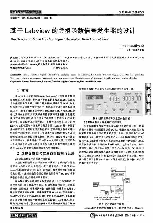
本仪器功能主要包括四类函数信号一正弦波、方波、三角
波、锯齿波的输出,频率的倍乘与微调相结合,以及实现输出波形 的直流偏置、电压幅度的控制等功能。具体指标如如表1所示:
表1虚拟函数信号发生器性能指标
输出波形
四种波形:方波、正弦三角波、锯齿 波任意选择
输出频率范围
r712100陕西杨凌西北农林科技大学机械与电子工程学院)
李红军杨中平胡真明
(Northwest A&F University,Mechanical and Electronic Engi-
neering College,Yangling Shanxi 712100)Li Hongjan Yang Zhongping Hu Zhenming 通讯地址:(712100陕西杨凌西北农林科技大学机电学院2004 级研究生16号信箱1李红军
4总结
Labview作为一个图形化编程软件。是开发测试系统的一 种功能强大、方便快捷的编程工具。其良好的相通性、开放性、 专用性,使测试系统的开发周期短、成本低、质量高。基于 Labview的虚拟函数信号发生器具有机交互性好、易于操作等 特点,能够广泛的应用与于科研、生产等领域.
本文作者创新点:采用Labview设计了一虚拟函数信号发 生器。该虚拟函数信号发生器能够产生正弦波、三角波、方波、 锯齿波等波形,频率动态范围较宽且可微调。机交互性好、易于 操作等特点,能够广泛的应用与于科研、生产等(_F转第∞页)
Abstract:A Virtual Function Signal Generator is designed Based on l_abview,The Virtual Function Signal Generator can generates Sine wave,triangle wave,square wave,teeth of a saw wave…etc。Dynamic range of frequency is wide and Can regulate slishtly. Keyword:Virtual Instrmnent,Labview,Function Signal Generator,data acquisition card
基于声卡的虚拟信号发生器的设计
目录摘要 (3)Abstract:In order to achieve virtual instrument software development platform and the computer sound card's digital processing between the application of virtual technology to improve the promotion and expansion, this paper presents a virtual sound card based Signal Generator design. The program uses an ordinary PC sound card as a signal of the output channels, with LABVIEW software to complete the design of the virtual signal generator. Experimental results show that the virtual signal generator can achieve the traditional function of the basic functions of the signal generator (3)1 引言 (3)论文研究背景 (4)论文研究意义 (4)研究现状 (4)设计要求 (5)2 声卡与LABVIEW连接 (6)声卡设计的结构 (6)声卡设计参数 (6)声卡与LABVIEW的连接配置 (7)控件的介绍 (7)声卡的连接设计 (7)3 虚拟信号发生器的设计 (10)虚拟信号发生器的程序框图 (10)波形类型切换模块 (10)频率粗调模块 (11)频率细调模块 (11)幅度和矩形占空比可调模块 (12)虚拟信号发生器总图 (13)4 系统的调试 (14)测试设备 (14)4.2使用说明 (14)调试步骤 (15)调试结果 (17)频率调节的测试 (17)幅度调节的测试 (22)数据测试 (25)综合测试效果图 (25)5 结论与展望 (26)结论 (26)5.2展望 (27)参考文献 (27)致谢 (29)附录 (30)基于声卡的虚拟信号发生器的设计职业技术教育学院应用电子技术教育吉卫香(07440108)指导老师:林祝亮摘要:为了实现虚拟仪器软件开发平台与计算机声卡的数字处理技术之间的应用,提高虚拟技术的推广和扩充,本文提出了基于声卡的虚拟信号发生器设计方案。
基于LabVIEW的虚拟信号发生器的设计与实现_张黎
图 4 正 弦 波 产 生 部 分 程 序
5.2 锯 齿 波 的 实 现 锯齿波函数的调用路径:函数→信号处理 → 信 号 生 成
→ 锯 齿 波 。 执 行 上 述 操 作 后 ,出 现 如 图 5 所 示 函 数 。
图 7 正 弦 波 产 生 前 面 板
图 5 锯 齿 波 生 成 函 数
Abstract:LabVIEW is a graphical programming language developed by National Instruments.The software is simple to use and convenient which provides a large number of data acquisition and processing library functions.Based on the plat- form of LabVIEW,the virtual signal generator is designed using virtual instrument technology.It can communicate with hardware by calling DLL,complete data processing according to algorithm and output signals by data acquisition card. This system can generates sine wave,square wave,triangle wave and sawtooth wave.Parameters of this system,such as frequency and amplitude,can be changed.The system is stable and flexible. Keywords:virtual instrument;signal generator;LabVIEW
Parameterized FIR Filtering IP Cores for Reusable SoC Design
Parameterized FIR Filtering IP Cores for Reusable SoC DesignUmar Farooq, Muhammad Saleem, Habibullah JamalDepartment of Electrical Engineering, University of Engineering & Technology Taxila, Pakistan.AbstractIn this paper, Intellectual Property (IP) cores for unfolded direct form (UDF) and folded direct form (FDF) FIR Filters are presented. The proposed IP Cores are parameterized and programmable in terms of data bits, coefficient bits, filter order and the type of filter (Low pass, High Pass, Band Pass etc). The IP Cores are implemented for 8 bit and 16 bit data and coefficient widths on XC3s1000ft256-4 device. The parameterized IP cores can be used for reusable System-on-Chip (SoC) design. Core architectures of UDF and FDF FIR Filter are described in detail and favorable results for area/speed performance are reported.Key words: IP Core, Finite Impulse Response (FIR) filter, Unfolded Direct Form (UDF), Folded Direct Form (FDF), SoC design, Parameterized, Synthesis tools1. IntroductionDesign productivity is significantly behind what the semiconductor technology can deliver [1]. A cost effective design methodology is desired to find means of increasing design productivity to benefit from the capacity increases made possible by the semiconductor process technology [2]. In order to reduce product cycle time and development cost, it is necessary to reuse complex pre-designed blocks, the Intellectual Property (IP) modules or Virtual Components (VC). IP-based SoC design methodology is a hot research area that is bridging the gap between design productivity and silicon capacity [3]. High quality of IP Core is critical for successful reuse and integration of IP cores. IP core should be as much configurable as possible [4], [5] . Parameterized IP Cores provide the means to tailor their functionality to what the customer really requires. Hence parameterized IP Core based SoC design is very desirable [6], [7].Finite Impulse Response (FIR) IP Cores are important blocks in both audio and video signal processing [8]. In digital systems, noise reduction, echo cancellation etc are repetitively executed with the help of FIR filters. There are two types of implementation approaches, parallel and sequential [9]. The parallel implementation has higher throughput but it requires a large number of adders and multipliers. The sequential implementation needs single multiplier and is favorable in terms of cost and area performance. Most of the researchers have implemented FIR Filter IP Cores using parallel architecture [10], [11], [12]. These architectures use multiple data paths where Coefficient Segmentation Algorithm and data Block-processing are required. To minimize the overheads, the sequential implementation of FIR Filtering IP core, is preferred.FIR filter can be realized in unfolded direct form, folded direct form and transposed form. The digital filters are built by the combination of several digital building blocks such as adders, multipliers, mac, muxes and memories etc [13], [14], [15]. The design of identical function with different data widths is possible with the help of Hardware Description Languages (HDL’s) and Synthesis tools.The main objective of this work is to present a design methodology for an FIR Filtering IP Core that is parameterized and programmable. The sequential implementation is selected to minimize the overheads of design. The proposed architecture has capability of run time programmability for SoC design. Type of filter, number of coefficients, word length for input data and filter coefficients can be changed.This paper presents the design methodology for implementation of folded and unfolded FIR Filtering IP Core architecture. The control logic and the data path are designed with the characteristics that they are parameterized and programmable. Synthesis results of 8-bit coefficients & data, and 16-bit coefficients & data, are presented. The IP Cores are described in Verilog HDL and implemented on Spartan 3 family.The paper is organized as follows. A brief introduction of digital filter architectures is given in Section 2. The proposed architectures for folded direct form (FDF) and unfolded direct form (UDF) FIR Filter IP Core are introduced in Section 3. Simulation results are discussed in Section 4 and finally the paper is concluded in Section 5.2. Digital Filter Architectures2.1 Unfolded Direct Form (UDF)An FIR digital filter can be implemented using different architectures. Some researchers use parallel architecture where high throughput is obtained at the cost of large number of multipliers. In sequential architectures, single multiplier and mac unit is needed along with control logic [13], [14]. The input-output relationship of linear time invariant (LTI) FIR filter can be written as follows [14].M-1Y(n) = bm .X(n – m) (1)m=0Here M represents the length of FIR filter, bm are the filter coefficients, X(n – m) denotes the data samples at time (n – m) and Y(n) represents output data. The filter coefficients can be calculated using “fda tool” (filter design and analysis tool) of Matlab. The direct implementation of Eq.(1) is called as the unfolded direct form. The architecture of UDF FIR Filter is shown in Fig.1.Y(n)Fig.1 The UDF FIR Filter architecture2.2 Folded Direct Form (FDF)Every linear phase FIR filter has symmetrical coefficients around the middle one. The symmetrically located coefficients can be added before multiplication. So the amount of multiplication required to calculate an output sample can be reduced to half by using Folded Direct Form architecture.For FDF filter, Eq.(1) can be written in the following form.Y(n) = b 0(X(n) + X(n – (M-1)) + b 1(X(n-1) + X(n –(M-2)) + ….(2)The structure for mapping of Eq.(2) on hardware isshown in Fig.2. For this folded architecture pre-adder isrequired to add the symmetrically located data samplevalue and then multiplied with the respectivecoefficients. Similarly the 2nd data sample value and 2nd last data value are added on single clock and multipliedwith respective coefficient value and so on.Y(n) Fig.2 The FDF FIR StructureIt is obvious that a large number of multipliers & adders to the extent of filter order are required in UDF scheme. In case of FDF implementation, number of multipliers is reduced to half. However, the same may be implemented sequentially by using single multiplier and pre-adder as explained in the next sections. 3. Proposed Architecture of FIR Filtering IP Core 3.1 UDF FIR IP CoreThe design methodology of UDF FIR Filter IP core is discussed here. The basic data flow diagram of UDFFIR core is given in Fig.3.Fig.3 UDF FIR Filter Data Flow diagramFrom Fig.3, the main component is control logic that is implemented in the form of a controller. In addition to a controller block, two memory blocks, a data path (mac unit, multiplier, and adder) and a rounding unit are used. Two input and one output registers are also used. These modules are parameterized and programmable. They can be changed dynamically and can be reused. The word length for coefficients and data can be changed to any value (4bits, 8 bits, 16 bits etc). The type of filter (low pass, high pass, band pass, band stop) can be changed and number of taps (coefficients) of the filter is programmable. The following specifications were considered to design the IP Core. No. of Coefficients = from 2 to 128 Word length of data & coefficients= from 4 to 16No. of mac units = 1Data RAM size = 16 x 128Coefficient RAM size = 16 x 128The filter coefficients were obtained from “fda tool” of Matlab. A controller was designed using Verilog HDL. The coefficients were loaded in Coefficient RAM with the load signal high. This signal was kept high for a number of cycles depending on the length of filter.When load signal goes low, it resets all modules exceptthe coefficient RAM. The block diagram and internal architecture of the Controller is shown in Fig.4.Fig.4 Internal Architecture of ControllerThe controller is designed to generate five output signals depending on the status of input signals. It consists of the following components.Counter_conv moduleWrite_gen moduleRam_addr moduleRam_enable moduleOut_enable moduleThe counter_conv module is a simple down counter that will down count with each clock. It starts from the maximum number that is equal to length of the filter and down counts to zero, then goes back to maximum. The write_gen module is another down counter but thefrequency of this module is 1/(length of filter) times the clock frequency. The ram_enable module generates enable signal for write operation in the ram. The ram_addr module is designed to generate read address for the ram. The out_enable module controls the output enable signal for the mac unit, rounding unit and out_reg unit.The single multiplier architecture for UDF FIR IP Core implementation is shown in Fig.5. Fig.5 UDF FIR IP Core ArchitectureThe sequence of operations is now explained. The input data and coefficients of the filter are taken one by one from two separate RAM’s by getting signal from the controller and are multiplied. The output of the multiplier goes to an adder where it is added to the previous product. The output of adder is supplied to mac unit and output of mac provides the output Y(n).All the components of this core are parameterized and programmable. They were implemented using Verilog hardware description language.3.2 DFD FIR IP CoreThe basic data flow diagram of Folded Direct Form(FDF) FIR core is shown in Fig.6.RFig.6 Data Flow Diagram of FDF FIR FilterIn this architecture small change in controller section isrequired. Here, two read addresses for data ram are generated in single clock cycle, to get two data sample values added before multiplication with the respective coefficient. Moreover small change for data ram is also required i.e two read address busses, two output data busses and one write address bus for writing the data on respective location. A pre-adder is required in this core to add the symmetrically located coefficients.The addressing scheme adopted for generation of read and write address is implemented using the circular buffer similar to unfolded direct form FIR core. The only difference regarding folded architecture is that two read addresses on single clock are generated for data ram. The coefficients ram address length also is half of unfolded direct form ram for same number of taps of filter.The modification in data ram for folded architecture is shown in Fig.7. For this ram two de-multiplexers are required. Two outputs according to the addresses generated by controller i.e data sample values location are available for addition and then multiplied withrespective coefficients to get the output of the core.Fig.7 FDF FIR Filter RAM internal architecture 4. Simulation ResultsThe building blocks of the architecture shown in Fig.5 & Fig.6 were synthesized using Leonardo Spectrum. The filter coefficients were obtained using Matlab “fda tool”. The coefficients were converted to fixed point format for input to the core. The output results of the core were converted to floating point numbers by the Matlab. The proposed filter was also evaluated in the test bench. To verify the output of cores modelsim and matlab tools were used. The synthesis results of the UDF and FDF FIR cores for 8 bit and 16 bit word lengths are given in Table 1 and Table 2 respectively.Table 1:UDF FIR Core Synthesis Results. Description of Resources Used UDF, 16 Bit, 11 Tap UDF, 8 Bit, 11 Tap Slice register 405 out of 1536213 out of1536Flip Flop 85 53Latches 320 160 4 input lookup table 752 out of 1536329 out of 1536IOB FF 17 9IOB Latches 32 16Total Equi gate count for design10040 4496 J. Tag gate count for IOB’s 2736 1585 External GCLK IOB’s 1 out of 4 1 out of 4 Max Freq 35.464 MHz 42.7 MHzTable 2 FDF FIR Core Synthesis ResultsDescription of Resources Used FDF, 16 Bit,11 TapFDF, 8 Bit,11 TapSlice register 420 out of1536228 out of 1536Flip Flop 132 84Latches 288 1444 input lookup table 913 out of1536421 out of1536IOB FF 17 9IOB Latches 32 16Total Equi gatecount fordesign11476 5409J. Tag gatecount forIOB’s2688 1536ExternalGCLK IOB’s1 out of 4 1 out of 4Max Freq 31.329 MHz 43.324MHzIn case of folded architecture, the area requirement is larger as compared to unfolded direct form. It is due to the fact that two multiplexers are used in data ram and two address buses are required to generate two read addresses. The word length and number of taps of filter can be changed readily.From the results, it is clear that the Core is parameterized and programmable.5.ConclusionsDesign methodology for UDF and FDF FIR Filtering IP Cores was presented. The basic architectures and data flow scheme was devised and implemented. The component modules were described in Verilog HDL. The synthesis results were obtained using LeoSpec. The results show that the proposed IP Core is parameterized and programmable. The parameterized cores are an essential component for IP based SoC design. The core can be optimized for different data and coefficient widths. The work will be extended to implement folded direct form using distributed arithmetic and reusable SoC design based on IP cores, will be explored further. References[1] International Technology Roadmap for Semiconductors ITRS:2005, Semiconductor Industry Association, .[2] Michael Keating and Pierre Bricaud, “Reuse Methodology Manual for System-on-a-Chip Designs”, Kluwer Academic Publishers, 1998.[3] Daniel D. Gajski, Allen C.-H. Wu, Viraphol Chaiyakul, Shojiro Mori, Tom Nukiyama and Pierre Bricaud, Essential Issues for IP Reuse, IEEE J., 2000. [4] Warren Savage, John Chilton and Raul Camposano: “IP Reuse in the System on a Chip Era”, IEEE Journal 2000.[5] Han Qi, Liang Yu and Wei Tong Li: “IP-Based SoC Design Methodology”, Proc. Of World Computer Conf., August 2000.[6] ZHAOJunchao, CHEN Weiliang and WEI Shaojun: “Parameterized IP Core Design”, No. 0-7803-6677-8/01, pp.744-747, 2001 IEEE[8] A.T.Erdogan, M. Hasan, and T.Arslan, “Algorithmic low power FIR cores”, IEE Proc. Circuits Devices Syst. Vol-150, No.3, June 2003.[9] C.H. Wang, A.T. Erdogan, and T. Arslan : “High Throughput and Low Power FIR Filtering IP Cores”,O-7803-8445-8/04 2004 IEEE.[10] Vijay Sundararajan, Keshab K.Parhi , “Synthesisof Low Power Folded Programmable Coefficient FIR Digital Filters”; IEEE, 2000.[11] Jongsun Park, Khurram Muhammad, and Kaushik Roy: “High-Performance FIR Filter Design based on sharing multiplication”, Trans. IEEE Trans. On Very Large Scale Integration (VLSI) Systems, Vol.11, No.2, pp.244-253, April 2003.[12] Zhangwen Tang, J ie Zhang and Hao Min, “A High Speed, Programmable, CSD Coefficient FIR Filter”; IEEE Transaction on Consumer Electronics, Vol.48, No.4, November 2002.[13] A.T.Erdogan, T.Arslan, “Low Power Implementation Of Linear Phase FIR Filters For Single Multiplier CMOS Based DSPs”; IEEE International Symposium on circuits and systems(ISCAS’98),1998 [14] A.T.Erdogan, E. Zwyssig, and T.Arslan, “Architectural trade-offs in the design of low power FIR filtering cores”, IEE Proc. Circuits Devices Syst. Vol.151, No.1, February 2004.[15] C.H. Wang, A.T. Erdogan, and T. Arslan : “Algorithmic Implementation of Low-Power High Performance FIR Filtering IP Cores”, Proc. 18th Int. Conference on VLSI Design (VLS2688ID’05), 1063-9667/05 2005 IEEE.。
chapter 6 signal(信号)
The kernel can perform one of three actions, depending on what the process asked it to do:
2015-Linux System Programming
Signal Concepts
Ignore the signal:
Catch and handle the signal:
The kernel will suspend execution of the process’s current code path and jump to a previously registered function. The process will then execute this function. Once the process returns from this function, it will jump back to wherever it was when it caught the signal. SIGINT and SIGTERM are two commonly caught signals. Processes catch SIGINT to handle the user generating the interrupt character. Processes catch SIGTERM to perform necessary cleanup.
Chapter 5: Signal
2015-Linux System Programming
Overview
Signal Concepts Basic Signal Management Sending a Signal Reentrancy Signal Sets Advanced Signal Management A Flaw in Unix?
- 1、下载文档前请自行甄别文档内容的完整性,平台不提供额外的编辑、内容补充、找答案等附加服务。
- 2、"仅部分预览"的文档,不可在线预览部分如存在完整性等问题,可反馈申请退款(可完整预览的文档不适用该条件!)。
- 3、如文档侵犯您的权益,请联系客服反馈,我们会尽快为您处理(人工客服工作时间:9:00-18:30)。
The Design of Virtual Function Signal GeneratorChen YunYunSchool of Energe and Power Engineer, YangzhouUniversityYangzhou 225009 ChinaXiaocloud1201@Abstract—In this paper, a Virtual Function Signal Generator is designed Based on Labview. How to design the generator is introduced in detail. The Virtual Function Signal Generator can generate basic wave such as Sine wave, formula wave, white noise etc. The generator has functions like wave showing and date saving in addition.Keywords- Virtual Instrument; Labview,;Function Signal GeneratorI.I NTRODUCTIONThe function signal generator is applied in great many of fields. Virtual Instrument is a new type of instrument which has especial functions that old one do not have. One VI includes PC, hardware which is particularly designed and special software. Being a graphical programming language Labview is used for date gathering, instrument controlling and date analyzing. How to design virtual function signal generator by Labview is explained in detail in the following paper.II.T OTAL D ESIGNAccording to the principle of function signal generator, four parts were designed to compose virtual function signal generator. These four parts are property setting, signal generating, wave showing and date saving.A.Panel of GeneratorIn this system the panel are divided to property setting panel (fig. 1) and total structure panel (fig.2). Main options in the first one are frequency, amplitude, duty cycle and samples etc. about signal. These properties can be set in this panel. Total structure panel just includes four parts that were presented above and some additional parts.B.Function about InstrumentsThe Virtual Function Signal Generator can generate basic waves such as Sine wave , special waves like formula wave and some kinds of noise. Signal’s frequency can be regulated delicately or roughly. Property can be reset quickly and be used as subprogram sometimes. Moreover has the generator functions like wave showing and date saving etc.III.S OFTWARE ABOUT V IRTUAL F UNCTION S IGNALG ENERATORThe Virtual Function Signal Generator was designed base on Labview 7.0. There are three modules which compose this system: module of property setting, wave generating, wave showing and saving.A.Module of Property SettingFrequency setting and property resetting are two important parts of this module. How to change frequency value multiply is explained in fig.3. Node Selectting is applied repeatedly and skillfully so that data can be input in many channels. Then select data by switch button. So frequency controlling can be designed as real instrument. How to reset property quickly is explained in fig.4.Figure 1. Property Set Panel2009 International Conference on Energy and Environment TechnologyFigure 2. Total Structure PanelFigure 3. Frequency ControlFigure 4. Property ResetB.Module of Wave GeneratingThis module is the core of the Virtual Function SignalGenerator. Structure CASE is used in this work. By specialnode many types of waves can be generated. For example,how to generate sine wave is explained in fig.5. The otherones can be generated in similar way.C.Module of Wave Showing and SavingIn fact this module is a composite one which includemany functions as operating, applying, debugging, showingetc. Because of lots of acts would be operated though thisinterface, this interface must be not only practical but alsonice. Fig.6 just explained how to solve these problems.Figure 5. Graphical Program about Sine Wave GenerateFigure 6. Graphical Program about totalIV.C ONCLUSIONBeing graphical language, Labview is very strong and easy tool to make system of measure and test. Virtual Function Signal Generator based on Labview has advantages such as having friendly interface, operating easily etc. It can generate many types of function signals which have big range of value of frequency and its output datas can be saved. So it can be applied widely.R EFERENCES [1]Xianglou Liu,Wuhe.”New Type of Virtual Function Signal Generatorbased on Labview”. Chemical Automation and Instrument [J],2005,32(6):65-67[2]Shuizheng Xie.” The Design of Virtual Function Signal GeneratorBased on Labview”. Microcomputer Information [J]. Beijing:Publisher of Defence Industry. 2007 Vol.23 1-1 181-182.[3]WangLei,TaoMei. ”Master LabVIEW 8.0” [M]. Publisher ofElectronic Industry. 2007.01.[4]Jianan Cai, Jiehua Chen. “Appling of Engineer Software based onLabview” [M]. Publisher of Chongqing University,2006.。