气缸使用说明书 十
格罗莱诺悬挂气缸itar系列说明书

INSTALLATION INSTRUCTIONSPRODUCT SAFETY & LEGAL DISCLAIMER© 2016 Go Rhino Products. All rights reserved 589 W. Apollo St., Brea, CA 92821 P: 888 427 4466•IMPORTANT READ ALL INSTRUCTIONS CAREFULLY BEFORE INSTALLING, FAILURE TO DO SO MAY CAUSE PERSONAL INJURY OR DAMAGE TO PRODUCT AND/OR PROPERTY. •Review the product package and contents prior to beginning the installation. Take care whenopening the packaging and removing items. If a return is needed you will want to return the product inits original packaging if possible.•This instruction guide is provided as a GENERAL installation guide, some vehicles vary dimensionally and may require additional steps. •Test fit the product on the vehicle prior to any third party modifications and or finishing. Themanufacturer and/or distributors do not accept responsibility for third party charges, labor and orthird part replacement modifications. Some modifications may void the factory warranty.•Exercise due-diligence when installing this product. The manufacturer and distributors of this productdo not accept any responsibility for vehicle damage or personal injury resulting from the installation ofthis product. Careless installation and operation can result in serious injury or equipment damage.•This product is for general off-road use. All liability for installation and use rests with theowner/operator.•INSTALLER: Once installation is complete, please return this guide along with other documentationincluded in this product back to the consumer for future reference. The manufacturer/distributors ofthis product do not guarantee this particular version will be available at a later date.V . 3 05.13.2016PART NO.●5950120T PRODUCT DESCRIPTION:●Overland Series GearAccessory PlateAPPLICATION:●Universal5950020TINSTALLATION INSTRUCTIONS INJURY HAZARDPlease complete a shop and tool inspection prior to beginning the installation.•Always make sure you have a clean, dry and well lit work area.•Always remove jewelry, loose fitting clothing and wear protective gloves and eye protection.•Always use extreme caution when jacking or raising a vehicle for work. Set the emergency brake and use tire/wheel blocks and jack stands. Refer to the vehicle manufacturer hand book. Utilize the vehicle manufacturers designated lifting points.•Always use appropriate and adequate care in lifting parts during disassembly and installation. Seek help in lifting heavy or large items into place. Utilize jacks and or lifting devices when available.•Always insure products are secure during disassembly and installation.•Always wear eye protection and take steps to protect any exposed skin during the installations. Drilling, cutting and grinding plastic and metal may create flying particles that can cause injury.•Always use extreme caution when drilling, cutting and or grinding on a vehicle. Thoroughly inspect the area to be drilled, on both sides of material, prior to modification and relocate any objects that may become damaged.•Always assemble and tighten all fasteners per the installation instructions.•Always route electrical cables carefully. Avoid moving parts, parts that may become hot and rough or sharp edges.•Always insulate and protect all exposed wiring and electrical connections.MAINTENANCE AND CARE•Always perform regular inspections and maintenance on mounts and related fasteners.•Periodically check and tighten all fasteners.•Stripped, fractured, or bent fasteners must be replaced.•After washing the vehicle make sure to fully dry all surfaces.•In areas with cold temperatures make sure to wash the product often to remove harmful materials used on road ways.•Never use abrasive cleaners or polish compounds. Clean with a gentle soap and water. If you use wax use a non-abrasive automotive wax such as pure carnauba wax.WARNINGSome products have been designed to work together with factory rear sensor systems, factory forward facing sensor systems and factory air bags.•Installation of some of these products may alter the factory sensor system performance.•Factory sensors may read shackles or hooks protruding from the fairlead and or tow hooks.•All sensor testing is completed by Go Rhino Products and or third party testing labs on modified vehicles.•Sensor sensitivity, factory sensor housing, orientation, and operating conditions are all variables that will influence functionality of the sensors.•Installation of some product may effect the factory air bag systems.•Some products allow the use of third party products such as winches, shackles, hooks, etc. Follow the respective manufacturers operating instructions for use with our products.•Make sure to fully understand the product, it’s intended use and operation prior to use.Go Rhino recommends you, the installer, read this installation instruction manual from front to back before installing the product. You may also click here to view an installation video or visit /Installation-Videos.INSTALLATION INSTRUCTIONS If you need installation service for your new product, call the authorized distributor from whom you purchased theproduct or an authorized installation service company which can be found by calling toll free 1-888-427-44661/2 HourTOOLS NEEDED FOR INSTALLATION:•7/16” Socket •RatchetESTIMATED TIME FOR INSTALLATION: PARTS INCLUDED IN THIS LIST:ITEM QTY.PART NUMBERDESCRIPTION TORQUE ITEM QTY.PART NUMBER DESCRIPTION A 8AST-T870G41/4” x 3/4” Hex Bolt 8 ft-lbs D 8AST-TU19G41/4” Hex Nut B 8AST-RPR70G41/4" Lock Washer E 159500006AA Gear Accessory PlateC 8AST-RP21G41/4“ Flat WasherINSTALLATION INSTRUCTIONSStep-1Begin by determining the desired location for the Overland Series Gear Accessory Plate on your SRM Rack crossbars or Overland Rack crossbars or uprights.Step-2Install and position (2) ¼” x ¾” hex bolts in the center channel of each SRM Rack crossbar or Overland Rack crossbar or upright that will be used for attachment of the Overland Series Gear Accessory Plate (Fig 1).Step-3Align the ¼” x ¾” hex bolts installed in the crossbars or uprights with the holes in the Overland Series Gear Accessory Plate, and position the Overland Series Gear Accessory Plate on the crossbars or uprights so the ¼” x ¾” hex bolts are protruding through the attachment holes in the Overland Series Gear Accessory Plate.Step-4Secure the Overland Series Gear Accessory Plate to each crossbar or upright using the ¼” x ¾” hex bolts, (2) ¼” flat washers, (2) ¼” lock washers and (2) ¼” hex nuts, (Fig 2). Tighten the nuts and bolts.Fig 1Fig 2A Crossbar or UprightA-B C-D A-B C-D EGo Rhino warrants to Buyer that for a period of five (5) years from the date of shipment of the product(s) (“Warranty Period”) for black finishes and chrome finishes, that such products will materially conform to the specifications set forth in Go Rhino’s specifications in effect as of the date of shipment(s) and will be free from material defects in material workmanship.Go Rhino warrants to Buyer that for the life of the product(s) from the date of shipment of the product(s) (“Warranty Period”) for polished stainless steel finished products purchased after April 2004, that such products will materially conform to the specifications set forth in Go Rhino’s specifications in effect as of the date of shipments and will be free from material defects in materi al workmanship. Warranty claims must be accompanied with the original invoice and photos of the product. It is the customer’s responsibility to clean regularly and protect finish with regular applications of a nonabrasive polish that is compatible with the product’s finish.This warranty covers the cost of the product only and does not include the cost of removal, installation, third party modifications or shipping of the product. In no event shall Go Rhino be liable to buyer or any third party for any damage or harm caused by the product or use thereof, regardless of weather such damages were foreseeable and whether or not Go Rhino has been advised of the possibility of such damages, not withstanding the failure of any agreed or other remedy of its essential purpose. This warranty is void if the product shows signs of alteration, misuse, mishandling, improper care, neglect, improper application and/or damage due to improper installation. With respect to any such product(s) during the limited warranty period, Go Rhino shall, in its sole discretion, either: (i) provide a one-time repair or replacement of such products (or the defective part) or (ii) credit or refund the price of such products at the pro rata contract rate provided that, if Go Rhino so requests, Buyer shall, at Go Rhino’s expense, return such product(s) to Go R hino. The remedies shall be the Buyer’s sole and exclusive remedy and Go Rhino’s entire liability for any breach of the limited warrant (ies).Go Rhino disclaims all other warranties except to the extent that any such warranty cannot be validly disclaimed under applicable law.Finish Limited Warranty:Limited lifetime on stainless steel products (after April 2004)5 year warranty on black powder coat products5 year warranty on chrome productsThis warranty does not cover exposed weldsFinish warranty covers peeling, flaking, or cracking. Washing all finishes regularly with car wash soap and rinsing well with water is the best method for maintaining the finish on your products. You must also protect the finish with nonabrasive automotive wax on a regular basis. The use of any compound which contains abrasives becomes a self-defeating exercise as the compound scratches the finish and opens it to corrosion. The use of harsh chemicals used to remove bugs and tar may also cause the finish to fail and should be avoided.If you are unsatisfied with your purchase please contact the establishment you purchased the product from.If you need to place a warranty claim or need assistance, the Go Rhino customer service team will answer any questions you may have. Please contact the Go Rhino customer service team at 1-888-427-4466 during normal business hours Monday thru Friday 7 am to 5 pm PST. You may also email ********************. In order to better serve you please provide a copy of the original invoice / receipt, a photo of the issue you are experiencing and a photo of the vehicle the product is installed on. All warranty returns must have an approved RGA number. The RGA number must be clearly marked on the exterior of the return package. All approved warranty returns must be shipped to Go Rhino Products, 1002 Carriers Drive, Laredo, Texas 78045.INSTALLATION INSTRUCTIONSLIMITED WARRANTYPRODUCT REGISTRATIONPlease remember to register your new purchase. You may register your product at . Registering your product may help speed any future warranty or customer service inquiries. Thank you again for purchasing from Go Rhino Products Please take a few minutes to view additional products for your vehicle and more at These installation instructions are available on the Go Rhino web site along with installation videos formany of our products. 。
4G64(3)发动机使用说明书
4G64 S4 MPI 发动机使用说明书
3/16
试,确保曲轴减振皮带轮固有振动频率的稳定性,从而有效地降低了曲轴系统的扭曲
振动,使得曲轴可以在任何工况下可靠地工作,最大限度地降低了发动机的振动和噪
音。
曲轴减振皮 带轮
4)其它降噪减振机构 气门自动调整机构:由于液压挺柱的采用,气门间隙无需人工调整,液压挺注 可以自动吸收因环境温度变化及零件磨损导致的气门间隙,使气门间隙始终保 持为零,气门系统的噪音大大降低。 正时齿带及自动张紧器:曲轴正时齿带轮依靠正时齿带驱动凸轮轴和机油泵。 其特点是无变形、低噪音、无需润滑及重量轻等;以橡胶为基本材质,内含一 层玻璃纤维,确保正时齿带不收缩、不膨胀。采用自动张紧器来确保正时带的 在任何条件下保持张紧,该机构可以随着环境温度及负荷的变化自动调节,从 而降低发动机运转时的噪音,并且提高正时齿带的耐久性。
(e).良好的排放 4G64 S4 发动机为适应欧洲 2 号(EURO-II)排放法规采用了多种先进技术,包括采用热 线式氧传感器、电子控制的燃油蒸发回收系统、以及采用曲轴箱强制通风系统等。 1)采用热线式氧传感器 热线式氧传感器是指在氧传感器内有一个电加热元件,可在发动机起动后迅速将氧 传感器加热到工作温度,使排放更加有利。 2)采用电子控制的燃油蒸气回收系统 电子控制燃油蒸发回收系统由蒸气回收罐(炭罐)、净化控制电磁阀、蒸气分离阀及 相应的蒸气管道和真空软管组成。当发动机运转时,如果电磁阀开启,则在进气歧 管内真空吸力的作用下,空气从炭罐下方进入,经过活性炭从上方出口经软管进入 发动机进气歧管内,使吸附在活性炭表面的汽油分子又重新蒸发,随空气一起被吸 入发动机气缸内燃烧。经回收进入进气歧管内的汽油蒸气量必须加以控制,以防破 坏正常的混合气成分。这一控制过程由电子控制单元(ECU)通过控制净化电磁阀的开 启来实现。在发动机停机或怠速运转时,电子控制单元(ECU)使净化电磁阀关闭,从 汽油箱蒸发的汽油蒸气被炭罐吸收。当发动机以中高速运转时,电子控制单元(ECU) 使净化电磁阀开启,储存在炭罐内的汽油蒸气经过软管被吸入发动机内燃烧。 3)采用曲轴箱强制通风装置 曲轴箱强制通风系统的工作是由曲轴箱强制通风阀(即 P.C.V 阀)控制。它可将窜入曲 轴箱内的废气重新引入气缸内燃烧。P.C.V 阀根据进气歧管内真空度的不同,其控制 废气流量也将不同。
气动气缸使用方法说明书

气动气缸使用方法说明书使用方法说明书1. 产品概述气动气缸是一种常用的气动执行元件,用于将空气能转化为机械能,推动工作机构实现直线运动。
本使用方法说明书旨在帮助用户正确操作气动气缸,确保其正常使用和延长使用寿命。
2. 安全注意事项在使用气动气缸前,请务必注意以下安全事项:- 请确保工作场所通风良好,防止气体积聚。
避免使用于易燃、易爆、有害气体的环境中。
- 在操作气缸之前,请确保供气系统处于关闭状态,并检查供气压力是否符合气缸的额定工作压力。
- 气缸安装和维护操作应由经过培训并具备相关知识的人员进行。
- 在操作过程中,请不要用手直接触摸气缸以及相关连接部件,以避免意外伤害。
3. 气缸安装正确的气缸安装是保证其正常使用的基础。
请按照以下步骤进行安装:1) 将气缸与工作台面或设备固定装置连接,并确保紧固件牢固可靠。
2) 连接气缸的进气接头与供气系统,确保接头连接处无泄漏,并使用正确的密封件。
3) 根据工作需要,调整气缸的安装位置和方向,并确保其他零部件(如传感器、阀门等)正确安装。
4. 气缸操作正确的操作可以提高气缸性能和使用寿命。
请遵循以下操作规范:1) 在供气系统通电前,确保工作台面或设备上无障碍物,以免影响气缸行程。
2) 打开供气系统,调整供气压力,应根据气缸额定工作压力进行设置。
3) 控制气缸的运动方向,可通过控制阀门或电磁阀来实现。
请确保控制信号稳定可靠。
4) 在气缸运动过程中,避免超过其额定行程范围,以免损坏机械结构或引起意外。
5) 当气缸不需要工作时,请及时关闭供气系统,并确保排空气体,以避免气体积聚导致意外情况。
5. 气缸维护定期维护可有效延长气缸的使用寿命,并确保其性能稳定可靠。
请根据以下建议进行维护:1) 定期清洁气缸表面,去除尘土和污垢,并使用干净软布擦拭,切勿使用化学溶剂。
2) 定期检查气缸固定装置和连接件,确保紧固件无松动或损坏。
3) 检查气缸活塞密封件是否磨损或老化,如有问题应及时更换。
SMC锁紧气缸

添加标题
添加标题
添加标题
添加标题
气源压力:根据气缸工作压力和负 载情况选择合适的气源压力
环境因素:考虑气缸工作环境温度、 湿度、腐蚀等环境因素对气缸性能 的影响
使用注意事项
保持清洁:在使 用过程中,要保 持气缸的清洁, 避免杂质和污垢 的进入。
定期检查:定期 检查气缸的密封 件和连接部件, 确保其正常工作。
添加副标题
SMC锁紧气缸
汇报人:
目录
PART One
添加目录标题
PART Three
SMC锁紧气缸的分 类
PART Two
SMC锁紧气缸的概 述
PART Four
SMC锁紧气缸的应 用领域
PART Five
SMC锁紧气缸的选 型与使用注意事项
PART Six
SMC锁紧气缸的发 展趋势与未来展望
单击添加章节标题
在电子设备制造领域中,SMC锁紧气缸能够实现高精度的定位和夹紧,提高生产效率和产品 质量。
SMC锁紧气缸在电子设备制造领域中的应用还包括自动化生产线上的物料搬运、装配和检测 等环节,能够提高生产效率、降低人工成本。
SMC锁紧气缸在电子设备制造领域中还广泛应用于各种气动控制系统中,如气动门锁、气动 窗帘等,为设备的自动化控制提供了便利。
SMC锁紧气缸的发 展趋势与未来展望
技术创新方向
高效能:提高气缸的工作效率和响应速度 智能化:集成传感器和控制系统,实现气缸的智能控制 轻量化:采用新型材料和设计,降低气缸的重量 环保化:研发低能耗、低排放的气缸产品,满足环保要求
市场发展前景
市场需求持续增 长:随着工业自 动化的加速,对 SMC锁紧气缸的 需求将不断增长。
工业自动化是SMC锁紧气缸的重要应用领域之一,主要用于控制和调节工业生产过程中的 各种参数,如温度、压力、流量等。
主机气缸油注油器说明书
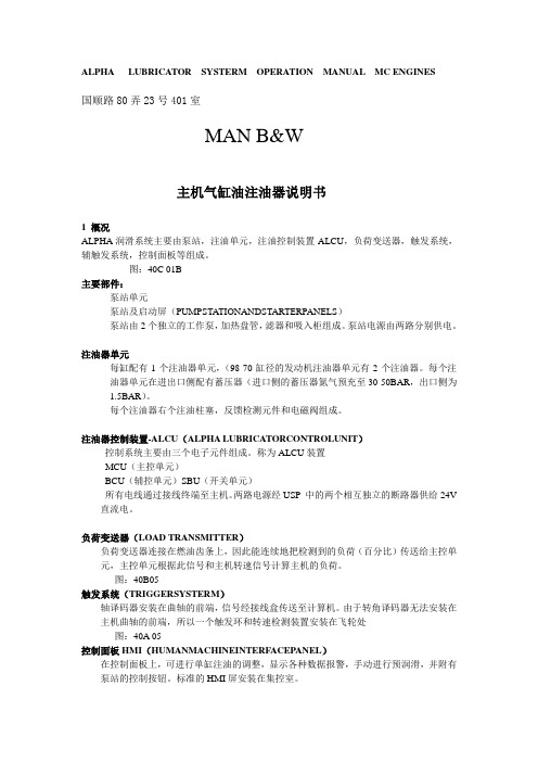
ALPHA LUBRICATOR SYSTERM OPERATION MANUAL MC ENGINES国顺路80弄23号401室MAN B&W主机气缸油注油器说明书1 概况ALPHA润滑系统主要由泵站,注油单元,注油控制装置-ALCU,负荷变送器,触发系统,辅触发系统,控制面板等组成。
图:40C 01B主要部件:泵站单元泵站及启动屏(PUMPSTATIONANDSTARTERPANELS)泵站由2个独立的工作泵,加热盘管,滤器和吸入柜组成。
泵站电源由两路分别供电。
注油器单元每缸配有1个注油器单元,(98-70缸径的发动机注油器单元有2个注油器。
每个注油器单元在进出口侧配有蓄压器(进口侧的蓄压器氮气预充至30-50BAR,出口侧为1.5BAR)。
每个注油器右个注油柱塞,反馈检测元件和电磁阀组成。
注油器控制装置-ALCU(ALPHA LUBRICATORCONTROLUNIT)控制系统主要由三个电子元件组成。
称为ALCU装置MCU(主控单元)BCU(辅控单元)SBU(开关单元)所有电线通过接线终端至主机。
两路电源经USP 中的两个相互独立的断路器供给24V 直流电。
负荷变送器(LOAD TRANSMITTER)负荷变送器连接在燃油齿条上,因此能连续地把检测到的负荷(百分比)传送给主控单元,主控单元根据此信号和主机转速信号计算主机的负荷。
图:40B05触发系统(TRIGGERSYSTERM)轴译码器安装在曲轴的前端,信号经接线盒传送至计算机。
由于转角译码器无法安装在主机曲轴的前端,所以一个触发环和转速检测装置安装在飞轮处图:40A 05控制面板HMI(HUMANMACHINEINTERFACEPANEL)在控制面板上,可进行单缸注油的调整,显示各种数据报警,手动进行预润滑,并附有泵站的控制按钮。
标准的HMI屏安装在集控室。
图:06A1-1 工作原理泵站供给注油器的压力为40-50BARMCU通过驱动注油器上的电磁阀实现注油控制注油后的反馈信号由该缸的指示单元上的发光二极管显示辅触发系统(BACKUP TRIGGER SYSTEM)辅触发系统由飞轮处盒子里的二个测速器组成,变送主机的转速信号至辅控单元。
A-T气缸手册

Pneumatic Piston Actuator Instruction ManualA-T Armaturen-Technik GmbHSafety Instructions & Regulations 安全说明和法规Meaning of notes注示的含义Hazard:危险Signifies that there is a danger of death, severe bodily injury or considerable damage to property if adequate measures are not taken.表示若不采取适当措施有存在生命危险,严重的身体伤害或者是巨大的财产损失Attention:注意Signifies that there is a threat of damage to property or the environment through non-compliance.表示不服从规章制度会对财产或环境造成破坏威胁Note:注Signifies the hint of a possible advantage when recommendations are followed.表示当遵循建议的时候会有优势提示General Safety Instructions 安全说明总括•It is the responsibility of the operator that current regulations for labour protection, the prevention of accidents and EU regulations are observed during the installation, operation and maintenance of any fittings and their accessories.操作员有责任在任何配件及其附件的安装,操作和维修期间遵守现劳动保护法规,事故预防以及欧盟法规。
广西玉柴机器股份有限公司 YCA、YC6B、YC6J 工程用系列发动机 使用说明书
YC6A 、YC6B 、YC6J 工程用系列发动机使用说明书YC6A 、YC6B 、YC6J Series Construction Engine Operation & Maintenance Manual使用前请仔细阅读使用说明书 Please read the Manual carefully before using. e p c at al o g s .c o m广西玉柴机器股份有限公司 Guangxi YuChai Machinery Co., Ltd.二00八年六月June.2008前 言Foreword 本说明书介绍了YCA 、YC6B 、YC6J 工程用系列发动机的主要结构、技术参数、主要附件的技术规格与数据以及使用和维护方面的基本知识,并对一些常见故障及其排除方法作了初步的介绍。
This Instruction Manual introduces the YCA 、YC6B 、YC6J series construction engine about its structure and technical parameters, the technical specifications and data of its main accessories as well as the basics information on use and service. It also describes some common malfunctions and solutions.为了使机器的优越性能得到更好的发挥,并保证机器的安全运行,请您在使用之前首先详细阅读本使用说明书,正确认识、了解与掌握YCA 、YC6B 、YC6J 工程用系列发动机的使用和维护要求,并特别注意以下的“安全行车注意事项”。
Please read this manual carefully to understand and master the operation and maintenance requirements about YCA 、YC6B 、YC6J series construction engine prior to e p c a t a l o g s .c o mputting the machine into operation and pay your particular attention to the Precautions for Safe Operation described below in order to enable the machine to bring its superior performance into full play and ensure its safe operation. 随着社会不断发展和需要,发动机将不断优化和提高,并不断增加变型设计的产品,除特别重大的设计变型外,本说明书不再作更改,因此过了一定的时间后说明书的介绍可能与实际的发动机有一定的出入,请以实物为准,敬请广大用户加以注意和谅解。
磁性开关气缸寿命测试安全操作及保养规程
磁性开关气缸寿命测试安全操作及保养规程一、引言本文档旨在确保对磁性开关气缸寿命测试的安全操作和正确保养,以保障设备的正常运行和延长使用寿命。
本文档适用于所有使用磁性开关气缸的操作人员。
二、安全操作规程1.着装要求–穿戴适当的工作服,并确保衣物没有悬挂物件。
–穿戴防滑鞋,确保脚下没有积水或其他滑动障碍物。
–使用防护手套,以保护手部免受可能的伤害。
–携带防护眼镜或面罩,以防止异物进入眼睛。
2.操作准备–在开始测试之前,确保所有设备已按正确顺序连接并处于正常工作状态。
–阅读并理解磁性开关气缸的使用说明书,并严格遵守其中的操作指南。
–确保测试环境中没有易燃物、化学品或其他危险物品。
3.操作步骤–在测试之前,确保磁性开关气缸没有受损或存在任何问题。
如发现有损坏,请立即停止使用,并进行必要的检修。
–在进行操作之前,确保测试区域不存在人员或其他障碍物。
–在进行气缸寿命测试时,应按照相关规范进行正确的测试参数设置。
–在测试完成后,关闭所有电源,并断开与电源的连接。
4.紧急情况处理–在出现紧急情况时,立即按下紧急停止按钮,并向相关人员汇报。
–紧急情况期间,禁止强行操作或修理磁性开关气缸。
只有在经过合适的维修人员检查和确认之后,才能继续使用。
三、保养规程1.定期清洁–定期清洁磁性开关气缸的外表面,以保持其良好的工作状态。
使用柔软的布或刷子,可擦拭或清除积尘或污垢。
–注意不要将水或其他液体直接喷洒在磁性开关气缸上,以避免损坏。
2.润滑维护–根据使用频率和工作环境,进行适当的润滑维护。
使用指定的润滑剂,并按照说明书上的建议进行润滑。
3.定期检查–定期检查磁性开关气缸的各个部件是否存在磨损或松动,如有问题应及时更换或修复。
–检查电线连接是否牢固,确保电线没有磨损或接触不良。
4.保养记录–记录每次保养的日期、操作内容和维护人员的信息。
这有助于了解磁性开关气缸的使用状况和维护历史。
四、总结磁性开关气缸寿命测试的安全操作和正确保养是确保设备正常运行和延长使用寿命的关键。
气缸使用说明书
气缸使用说明书一、概述气缸是一种常用的机械执行元件,用于转换压缩空气的能量为机械能。
本说明书将介绍气缸的基本结构、使用注意事项以及维护保养方法,以便用户正确使用气缸并延长其使用寿命。
二、气缸结构及工作原理1. 结构气缸一般由气缸筒、活塞、活塞杆、密封件、进气口和出气口等部分组成。
其中,气缸筒是气缸的主体部分,用于容纳压缩空气;活塞通过活塞杆与气缸筒相连接,并能在气缸内做往复运动;密封件用于保证气缸的密封性能。
2. 工作原理气缸的工作原理基本上是依靠压缩空气的作用。
在工作过程中,当气缸内的压缩空气通过进气口进入气缸筒时,活塞向前运动;当气缸内的压缩空气通过出气口排出时,活塞向后运动。
通过合理控制进气口和出气口的开闭,可以实现气缸的正常工作。
三、使用注意事项1. 安装在使用气缸之前,首先需要进行正确的安装。
安装时应注意以下事项:- 气缸应采用固定安装方式,并保证其与相应设备的连接牢固稳定。
- 确保气缸的进气口和出气口连接正确,并且密封良好,避免漏气现象的发生。
- 安装过程中,避免碰撞气缸,以免损坏。
2. 操作在正式使用气缸时,需要注意以下操作事项:- 在使用气缸前,应先检查气缸及其连接部分是否有损坏或松动情况,确保安全可靠。
- 根据实际需要,合理控制气缸的进气口和出气口的开闭,以保证气缸的正常工作。
- 在操作过程中,避免过度使用气缸,以免增加其工作负荷或损坏零件。
- 在气缸工作时,注意观察气缸的工作状态,发现异常情况及时停止使用并进行检修。
3. 维护保养为了延长气缸的使用寿命,定期进行维护保养是必要的。
以下是一些建议的维护保养方法:- 定期清洁气缸,避免灰尘和污垢积累,影响气缸的正常工作。
- 检查气缸的密封件是否完好,如有损坏应及时更换,以保证气缸的密封性能。
- 定期给气缸加油润滑,以减少磨损和摩擦,保持气缸的良好运行状态。
- 定期检查气缸的连接部分是否松动,如有松动应紧固,保证气缸的稳定性。
四、故障排除在使用气缸的过程中,可能会出现一些故障情况。
Festo 活塞杆气缸操作手册说明书
EX 标记
标记
II 2G
Ex h IIC T4 Gb
II 2D Ex h IIIC T120°C Db
Tab. 1
–20°C £ Ta £+60°C
2
适用文件
提示!
产品的技术参数在其他文件中可能存在差异。在易爆环境下操作时始终优先参 照相关文件中的技术参数。
有关产品的所有可用文件 è /pk。
冲。
6
维护和保养
– 定期检查设备的功能。间隔:两百万个运动周期或最迟 6 个月后。
在多尘环境中使用本设备时,导轨的使用寿命短于在颗粒物少的环境中使用。
– 根据环境条件以更短的间隔检查导向杆和轴承的功能。
7
故障排除
功能故障
补救方法
目检发现的外部损坏
可以听到活塞杆密封件泄漏
气缸安装件或活塞杆上的安装件不牢固 活塞杆上有干燥顽固的润滑剂残留物 活塞猛烈冲击末端位置
DSNU-…-EX4-…
活塞杆气缸
工作条件 | EX
8100806 2018-11f [8100814]
Festo SE & Co. KG Ruiter Straße 82 73734 Esslingen 德国 +49 711 347-0
8100806
原版操作手册的译本
1
提示! 在爆炸性范围之外吸入压缩空气。
提示! 逸出的废气可扬起堆积的粉尘并形成可能发生爆炸的粉尘环境。
提示! 压缩空气内的气溶胶可以引起静电。
提示! 应用的点火保护类型:c(结构安全)
– 请注意产品标签。 – 使用空位堵头或沟槽盖封闭不使用的开口。 使用终端位置缓冲 PPV 时: – 调整缓冲器,使活塞杆能够可靠地到达终端位置,且不会发生严重碰撞/反
- 1、下载文档前请自行甄别文档内容的完整性,平台不提供额外的编辑、内容补充、找答案等附加服务。
- 2、"仅部分预览"的文档,不可在线预览部分如存在完整性等问题,可反馈申请退款(可完整预览的文档不适用该条件!)。
- 3、如文档侵犯您的权益,请联系客服反馈,我们会尽快为您处理(人工客服工作时间:9:00-18:30)。
气缸使用说明书十
产品使用说明书
产品名称:
产品型号:
************有限公司
一、说明书的使用范围
本产品使用说明书是按气缸在一般气动系统中作为执行元件应用的情况下编写的,因此适用于一切普通单杆双作用、带缓冲的、无油润滑的、耐高温的,薄型的、方型的、微型的各种型号各种规格的标准气缸和在标准气缸基础上修改设计的非标准气缸。
同时也适用于普通标准气缸的基础上开发设计的各种特殊气气缸。
二、气缸使用条件
1、气缸使用系统压力、介质温度应符合各型号气缸基本参数表
规定的基本参数值(见产品样本)
2、驱动气缸的压缩空气必须清洁、水份少、为此在气动系统回路中必须使用分水过滤器。
3、为了润滑气缸内部在气动系统回路中必须安装使用油雾器(无油润滑气缸可不用油雾器)。
三、气缸安装使用
1、气缸开箱安装前应检查气缸在运输过程中有无损坏、两端连杆螺母或螺纹连接处有无松动,清除防锈油及防护罩(帽)方可安装使用。
2、气缸安装时应注意气缸活塞杆不宜承受偏心载荷或横向载荷,应使载荷的运动方向与活塞杆轴心线一致,对与长行程气缸负载和活塞杆的连接最好采用可活动的V型接头或关节接头。
无论任何安装形式都必须保证气缸安装底座有足够的刚度。
3、气缸缸体在水平使用时,可用“三点法”进行检验。
首先使用活塞杆与负载相连接,当活塞杆全部伸出时,在杆的中间放一水准仪观察水平情况;其次当活塞杆处于中间位置时,在靠近气缸前端盖处的活塞杆上放一水准仪观察情况;最后当活塞杆处于退回位置时,应无别劲现象。
长行程气缸卧式安装时,为了防止活塞杆下垂、缸筒变形,须设置适当支撑。
4、采用前后法兰、脚架式安装的气缸,应避免装螺栓直接承受推力或拉力的负荷。
5、采用尾部单双耳的气缸或中间摆动的气缸时活塞杆顶端连接
销位置应与安装件轴的位置处于同一方向。
尾部单双耳或摆动气缸应与安装架之间留有适当的间隙。
6、气缸安装完毕后应在无负载的状态下使用工作压力运行2—5次,检查气缸有无异常现象。
7、气缸调速。
对气缸运动速度有一定要求时,气动系统必须安装单向节流阀。
一般情况气缸水平安装排气节流气缸速度比较平稳。
气缸垂直安装用进气节流调速时首先将气缸连接负载,将速度调节阀调到调整范围中间位置随后调节减压阀的输出压力,当气缸速度接近规定速度时,即可确定为调定压力然后可用速度调节阀(节流阀)进行微调。
8、采用可调缓冲气缸,在运行前先把缓冲调节阀全部打开,然后逐
渐增大阻尼直到满意为止。
调节缓冲针阀时顺时针旋扭阻尼增大,逆时针旋扭阻尼减少。
四、气缸维护
1、气缸正常使用后,要经常检查系统中分水过滤器和油雾器的工作情况,即时放水加油,不供油气缸6个月在气缸滑动部加涂润滑脂。
2、采用尾部单双耳式或中间摆动气缸,应定期向尾座或摆动处
加润滑油。
3、气缸在使用过程中应定期检查气缸各部位,注意连接各部位有无松动。
气缸密封件有无泄露情况,发现问题及时修复,以防事故发生。