《HBHX-RCPS-C10型 工业机器人技术应用实训平台》系统说明书
3.1-3.3项目三工业机器人安装、连接(外围设备)与联调
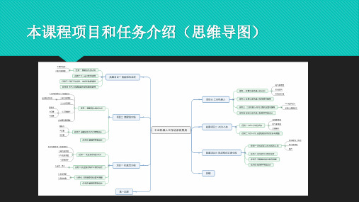
项目三 工业机器人安装、连接(外围设备)与 联调
子项目一 汇博工业 机器人认知
任务一 汇博工业机 器人机械结构与维
护
任务二 汇博工业机 器人电气控制原理
任务三 汇博工业机 器人末端执行器气 动回路连接与设计
3.1子项目一 汇博工业机器人认知(型号规格 )
HR20-1700-C10
3.1子项目一 汇博工业机器人认知(机械系统 组成)
子任务一 工业机器人外部工装安装 完成工业机器人末端真空吸盘、气动三爪卡盘以及部分气路连接: 1)吸盘与吸盘支架的安装,气管接头的安装; 2)三爪卡盘与支架的安装,气管接头的安装; 3)支架与连接杆的安装; 4)连接杆与末端法兰的安装; 5)末端法兰与机械手本体固连(连接法兰圆端面与机械手本体J6关
节输出轴末端法兰); 6)气管与气管接头的连接; 7)激光笔的安装。
3.1子项目一 汇博工业机器人认知(检修与维 护)
日常检查
3.1子项目一 汇博工业机器人认知(检修与维 护)
季度检查
3.1子项目一 汇博工业机器人认知(检修与维 护)
每年检查与每三年检查
3.1子项目一 汇博工业机器人认知(检修与维 护)
3.1 子项目一 汇博工业机器人认知(气动)
3.1 子项目一 汇博工业机器人认知(气动)
3.1 子项目一 汇博工业机器人认知(气动)
A PR
3.1 子项目一 汇博工业机器人认知(气动)
3.1 子项目一 汇博工业机器人认知(气动)
SPR
BA
3.1 子项目一 汇博工业机器人认知(气动)
3.1 子项目一 汇博工业机器人认知(气动)
每年检查与每三年检查
3.1子项目一 汇博工业机器人认知(机械零点 校对)
《HBHX-RCPS-C10型 工业机器人技术应用实训平台》系统说明书
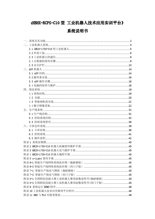
《HBHX-RCPS-C10型工业机器人技术应用实训平台》系统说明书一、系统及其功能 (2)二、工业机器人系统 (5)2.1 HR20-1700-C10型工业机器人 (5)2.2外部工装 (6)2.3工业机器人的通信 (9)2.4示教器的使用步骤 (9)2.5安全护栏 (13)三、AGV机器人 (14)3.1 AGV结构 (14)3.2磁导条安装 (16)3.3 AGV操作步骤 (16)3.4电磁的保养与维护 (18)四、视觉系统 (19)4.1系统结构 (19)4.2 光源 (20)4.3 智能相机的安装 (21)4.4数字图像采集 (22)五、生产线系统 (31)5.1生产线结构 (31)5.2 控制系统结构 (32)5.3 控制系统程序 (36)六、立体仓库系统 (39)6.1 立库结构 (39)6.2 控制系统 (41)6.3 操作流程 (42)附录1 系统实物图 (45)附录2 HR20-1700-C10机器人机械使用维护手册 (45)附录3 HR20-1700-C10机器人电气维护手册 (45)附录4 HR20-1700-C10机器人编程手册 (45)附录5 x-sight使用手册 (45)附录6-1智能生产线网络系统拓扑图(施耐德版) (45)附录6-2智能生产线网络系统拓扑图(西门子版) (45)附录7-1 智能生产线电气图纸(施耐德版) (45)附录7-2 智能生产线电气图纸(西门子版) (45)附录8-1全国职院技能大赛工业机器人赛项函数说明书(施耐德版) (45)附录8-2全国职院技能大赛工业机器人赛项函数说明书(西门子版) (45)附录9 系统运行DEMO程序 (46)附录10工业机器人技术应用赛项平台程序 (46)附录11 HMI与PLC对接变量表 (46)《HBHX-RCPS-C10型工业机器人技术应用实训平台》系统说明书一、系统及其功能工业机器人技术应用实训平台由工业机器人、AGV机器人、托盘生产线、工件盒生产线、视觉系统和立体仓库等六部分组成,如图1-1所示,系统实物图见附录1。
全国职业院校技能大赛工业机器人技术应用赛项(高职组)竞赛任务书
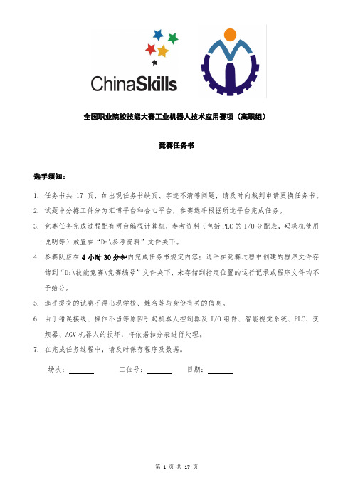
全国职业院校技能大赛工业机器人技术应用赛项(高职组)竞赛任务书选手须知:1.任务书共 17 页,如出现任务书缺页、字迹不清等问题,请及时向裁判申请更换任务书。
2.试题中分拣工件分为汇博平台和合心平台,参赛选手根据所选平台完成任务。
3.竞赛任务完成过程配有两台编程计算机,参考资料(包括PLC的I/O分配表,码垛机使用说明等)放置在“D:\参考资料”文件夹下。
4.参赛队应在4小时30分钟内完成任务书规定内容;选手在竞赛过程中创建的程序文件存储到“D:\技能竞赛\竞赛编号”文件夹下,未存储到指定位置的运行记录或程序文件均不予给分。
5.选手提交的试卷不得出现学校、姓名等与身份有关的信息。
6.由于错误接线、操作不当等原因引起机器人控制器及I/O组件、智能视觉系统、PLC、变频器、AGV机器人的损坏,将依据扣分表进行处理。
7.在完成任务过程中,请及时保存程序及数据。
场次:工位号:日期:竞赛设备描述:“工业机器人技术应用”竞赛在“HBHX-RCPS-C10型工业机器人技术应用实训平台”上进行,该设备由工业机器人、AGV机器人、托盘流水线、工件盒流水线、视觉系统和码垛机立体仓库等六大系统组成,如图1所示。
图1 竞赛平台结构图系统的工作目标是码垛机从立体仓库中取出工件放置于AGV机器人上部输送线,通过AGV 机器人输送至托盘流水线,由视觉系统对工件进行识别,然后工业机器人对工件进行分拣装箱。
图2为需要分拣的工件。
默认从左至右、从上到下工件编号为1-6号。
1 2 3 4 5 6图2 需要分拣的工件(汇博平台)1 2 3 4 56图2 需要分拣的工件(合心平台)托盘结构以及托盘放置工件的状态如图3所示,托盘两侧设计有档条,两条档条的中间为工件放置区。
图3 分拣工件放置于托盘中的状态系统中托盘流水线和工件盒流水线工位分布如图4所示。
图4 托盘流水线和流水线工位分布系统中主要模块的IP地址分配如下表1所示。
表1 主要功能模块IP地址分配表注意:码垛机单元的三个变频器的IP地址依次是:192.168.8.14;192.168.8.15;192.168.8.16选手不得用作其它模块。
C10系列工业机器人操作说明书

自动机器人平台使用说明手册1

2011年全国职业院校技能大赛高职组机器人赛项自动机器人平台说明目录第一章自动机器人平台概述 (3)1.1 自动机器人平台的总体构成...........................................................................................3 1.2 自动机器人平台按键部分...............................................................................................4 1.3 机器人平台的充电...........................................................................................................4 第二章自动机器人平台系统结构. (4)2.1自动机器人平台机械部分................................................................................................4 2.1.1 机器人平台机械部分组成...........................................................................................4 2.1.2 机器人平台运动详解...................................................................................................5 2.2 自动机器人平台控制系统...............................................................................................5 2.2.1 概述..............................................................................................................................5 2.2.2 主控制板. (5)2.2.3 巡线传感器..................................................................................................................9 2.2.4 传感器信号处理板.....................................................................................................10 2.2.5 电机驱动板................................................................................................................12 2.3 机器人平台控制程序.....................................................................................................14 2.3.1 控制程序流程图 (15)2.3.2 软件函数说明............................................................................................................17 第三章自动机器人平台的装配和调试 (18)3.1 机器人装配过程............................................................................................................18 3.1.1 主动轮电机装配.........................................................................................................18 3.1.2 电机安装至铝合金架板.............................................................................................18 3.1.3 从动轮及传感器安装.................................................................................................19 3.1.4 电路板的安装............................................................................................................19 3.2 机器人平台的调试 (21)第一章自动机器人平台概述自动机器人平台是专门为高职类机器人大赛提供的一个统一的机器人底盘,可以实现在比赛场地全场范围内的运动、定位;并提供了充足的I/O接口,参赛队可以根据大赛任务的要求,在此平台上进一步设计制作各种抓取、投放机构,利用机器人平台提供的主控制板和编程算法实现整体机器人的控制。
工业机器人综合认知平台需求说明
(3)运动指令·坐标系训练模块:可调节角度面板,模块表面有训练用图案及标定针。
(4)写字绘画模块:≥260×260mm画板。
)拆装台工具:手提工具箱、数字多功能万用表、5*75一字螺丝刀、5*75十字螺丝刀、小号螺丝刀套装、30cm橡胶锤、六寸尖嘴钳、五寸平口钳、S2长形球头内六角、七寸多功能剥线钳。
2)通过计算机软件对工业机器人的运作过程调试。
3)机器人控制数据库的建立和应用。
4)工业机器人轨迹程序的编写与调试。
5)工业机器人工具、工件坐标系的标定。
6)可编程控制器程序的编写和设计。
1.4 配套资源
1.4.1 实训资料
(1)配套课程教材、实训指导书;
(2)电子课件及其他课程资源。
1.4.2 配套支撑内容
(7)易损件清单:螺丝、螺母、橡胶防撞块、同步带轮不锈钢安装片、透明压线板、不锈钢限位块等。
1.3要求可完成的实训项目
(1)硬件的安装与调试
1)工业机器人底座的安装与调试技术。
2)工业机器人安装与调试技术。
3)机器人实训模块的安装与调试。
(2)编程调试和应用
1)工业机器人通过示教器对工业机器人的运作过程调试。
(2)装饰材质采用优质PVC 或亚克力,可灵活替换内容涵盖安全管理制度,标志标牌,实训室功能介绍等。
套
6
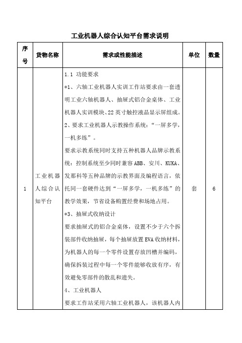
工业机器人综合认知平台需求说明
序号
货物名称
需求或性能描述
单位
数量
1
工业机器人综合认知平台
1.1 功能要求
*1、六轴工业机器人实训工作站要求由一套透明工业六轴机器人、抽屉式铝合金桌体、工业机器人实训模块、22英寸触控液晶显示屏组成。
虚拟实训平台:教学机器人安全操作模拟系统说明书
Safety Operation Simulation of Teaching RobotBased on VIRTOOLSLiang Zhang1,3, Rong Che3, Wensheng Huang1 and Bin Shen2,*1Ordnance NCO Academy, Army Engineering University of PLA, 430010, China2Wuhan Donghu University, 430212, China3National University of Defense Technology, 710106, China*Corresponding authorAbstract—At present, various colleges and universities have extensively carried out practical training courses for industrial robots. If students are trained entirely in actual equipment, they will be limited by the number of venues, equipment, complex structure, operation frequency and use safety. This requires students to carry out the necessary safety operation simulation training before carrying out the actual operation. Virtual safety training can effectively simulate the operation of robots, and design corresponding safety hazards to prevent students from misoperation. In this paper, a safety training simulation system is designed for the teaching robot. It provides an effective solution for the safety training of the teaching robot.Keywords—simulation; safety operation; VIRTOOLS; teaching robotI.I NTRODUCTIONAt present, various colleges and universities have extensively carried out practical training courses for industrial robots. If students are trained entirely in actual equipment, they will be limited by the number of venues, equipment, complex structure, operation frequency and use safety. The traditional video learning is simulated and can not be displayed. It can not complete the interaction between students and equipment, and can no longer meet the needs of the new situation. This requires students to carry out the necessary safety operation simulation training before carrying out the actual operation[1-7].Virtual safety training can effectively simulate the operation of robots, and design corresponding safety hazards to prevent students from misoperation. The application of virtual reality technology to the safety training of teaching robots is of great significance to the training of industrial robots. This is an important guarantee for training qualified robot operators. It effectively solves the problems of complex equipment structure, high price, limitation of site, quantity and type, and low training efficiency in robot training. Therefore, taking the teaching robot as the object, this paper designs a safety training simulation system, which provides an effective solution for the safety training of the teaching robot.II.O VERALL S TRUCTURE D ESIGN OF S AFETY T RAININGS IMULATION S YSTEMAccording to the system function requirement analysis and the selected realization way, the safety training system is designed mainly for the safety hidden danger of the teaching robot, such as speed limit, soft switch limit, collision restriction and so on. The software design of the system is as follows:The system uses Visual C++6.0 and the Virtools of Dassault company of France as the development platform of the system. Using Solidworks 3D design software and 3dsmax as modeling and animation generating tools, Access is used as the system database to store the sample part library[8-13].The simulation of safety training is the omnidirectional simulation of robot operation under the virtual environment. It is the theme of the robot safety operation, and the aim is to lay a solid foundation for the practical training in the future. Safety training simulation technology includes robot six axis motion simulation technology, robot safety hidden danger simulation technology and so on. The safety training simulation completes a series of action simulations according to the predetermined operation process. this simulation mainly uses keyboard operation method to simulate the operation of the robot teaching device, and completes the virtual communication between the teaching device and the robot through the bottom-level function, etc.The robot itself has a large number of parts. Generally, it belongs to large assembly. The 3D modeling technology provided by Solidworks software has a good effect in dealing with large assembly.The 3D model of the system is the foundation of the realization of the whole virtual assembly, and its quality directly affects the reality of the virtual environment. Because Virtools has no modeling function, it is necessary to use modeling software to build 3D solid models. But because this article is a mechanical product model, we first use the professional mechanical 3D drawing software Solidworks for modeling, and then import the built model into the 3dsmax, and then from 3dsmax to Virtools. Before establishing the model, a preliminary analysis should be carried out, and the complex mechanical products can be decomposed into several simple parts, and then the three-dimensional modeling of each component is carried out. After the model is established and successfully introduced into the 3dsmax, the model is given the material and the map, thus increasing the authenticity of the model, reducing the unnecessary polygons and improving the refresh rate of the display.3rd International Conference on Control, Automation and Artificial Intelligence (CAAI 2018)III.S IMULATION AND C ONSTRUCTION OF S AFETY T RAINING The system simulates the real operating environment as much as possible. And can design training subjects for typical security risks. In view of some difficult operation steps that are difficult to understand, real shot is taken, and the captured video stream is inserted into the software. After the end of the operation, play the demonstration video, so as to deepen the impression of students' operation, achieve the combination of virtual and reality, and improve the quality of training.A.Speed Control SimulationSpeed control is very important in robot operation. Ifstudents use high speed to complete manual operation, it is easy to have accidents when the fixture is close to the workpiece. Therefore, the simulation training of this subject is mainly focused on the speed control of manual operation. The system can increase or decrease the speed of the robot in manual or automatic way by pressing the combination of "Q", "A" and "Z". When the student moves the robot to the workpiece at a greater speed, the system alarms and the program stops running. After that, the system calls live video to remind students of incorrect operation. (See Figure I)FIGURE I. SPEED ADJUSTMENT OPTIONSB.Soft Switch Limitation SimulationOne of the common faults of students in real training is soft switching and limit fault. Many times this kind of fault makes it easy for the actual sensor to tighten the screw thread. Therefore, this training course was designed in safety operation training.The system aims at restricting the rotation range of each axis of the robot. When the user is about to exceed the range of its activity, the system will be warned, which suggests that the students use the method of robot to rotate safely. Here, we still use the video method to introduce the real clothes.C.Simulation of Moving Range Of RobotIn motion, robots are absolutely not allowed to bump into fixtures such as platforms, brackets, workpieces and so on. The result of the collision is that the robot generates an emergency stop fault and is very difficult to maintain. (See Figure II-III)FIGURE II. SPACE POSITION OF ROBOT CLAMPFIGURE III. SPACE POSITION OF ROBOT CONSOLE The system limits the range of motion of the whole robot. When students simulate operation, if there is a collision fault, they will call the police and call the system to stop the video to finish teaching with virtual reality.The key technology of robot collision is the collision distance discrimination of parts, which can be realized by using BBS and design VSL provided by Virtools. As shown in Figure IV and Figure V, the key BBS distance judgment and collision judgment are shown in the virtual assembly.FIGURE IV. DISTANCE JUDGEINGFIGURE V. COLLISION JUDGEINGIV.C ONCLUSIONCompared with the traditional training, the security simulation training has considerable advantages in improving the training flexibility, breaking through the trainingconditions and reducing the cost of equipment maintenance.Virtools software is powerful and easy to operate. It is very suitable for the development of similar systems.In view of the wide application of virtual maintenance training in practical maintenance training, this system mainly considers that the value of analog equipment can not be too high. It can reduce the cost of analog equipment as much as possible when the training effect is met. At the same time. The system requirements are analyzed from functional completeness, system availability and system reliability. The composition of the system and the framework of the system structure are given. This method provides a new way to realize the safety training system, and has important reference value for the training and popularization of large robots in China.R EFERENCES[1]T. M. Cheng, “A fast parametric deformation mechanism for virtualreality applications” [J], Computer & Industrial Engineering,2008,10(10):18-26.[2]Jeffrey L Wampler, et. Integrating Maintainability and datadevelopment[C]. In: Proceedings of the Annual Reliability and Maintainability Symposium, Tamp Bay, 2003. 255-262.[3]Pan Zhigeng, Cheok Adrian David. Virtual Reality and Mixed Realityfor Virtual Learning Environments[J]. Computer & Graphics, 2006, 30(1): 20-28.[4]Daniel Cohen-Or. A survey of visibility for walk through applications[J].IEEE Transactions on Visualization and Computer Graphics. 2003, 9(3):412-431.[5]Li J R, Khoo P. Tor B. Desktop Virtual Reality for Maintenance training:An Object Oriented Prototype System(V-REALISM)[J]. Computerin Industry, 2003, 52(2): 109-125.[6]Christopher M C, David C. Virtools Dev User Guide: Version 4.0[z].Virwols SA, 2006.[7]Virtools 5.0 Online Heferenee.[8]Richens P, Nitsche M. Mindstage: Towards a ftmetional virtualarchitecture[C]. Computer Aided Architectural Design Futures proceedings, 2005: 331-340.[9]Wutthikornthanawat w'Jinuntuya P,Rongviriyapanieh S, et a1.Multi-user tangible interface for public participation development oflow-cost housing project design and planning[C]. Proeeedings of the12th International Conference on Computer-Aided Architectural DesignResearch in Asia-Digitization and Globalizatin, 2007: 37-43.[10]Wang Xi, An Yang. Development ofgame software based on Virtools[J].Control and Management, 2007, 5(5): 160-162.[11]Li Xunxiang, Chen Dingfang, Wang Le, et a1. A developmentframework for V'trtools-based DVR driving systemiC]. Computer Supported Cooperative Work in Design, 2007: 188-196.[12]Pan VLin Z, Hu Z, et a1. Research on distributed multi. Screendis. playtechnique based on Virtools[C]. 7th Intemational Conferenee on Computer-Aided Industrial Design and Conceptual Design, 2006: 1-6. [13] D. U. Silverthom. Teaching and learning in the interactive classroom [J].Advances in Physiology Education, 2006, 12(30): 135-140.。
工业机器人理实一体化实训平台
供货产品技术规格偏离表
全部使用工业级控制芯片及成熟的控制电路,确保硬使用实时控制系统及重要数据的多重保护技术,确保
态的计算及自动控制;
实现机器人空间轨迹及状态的自动规划及自动控制;
总线传输底层协议,实现了数据的安
该单元软件通过可视化技术,让学生能够在三维图形世界中观察虚拟机器人,并通过手持盒交互式对机器人进品牌:华数
型号:HSR-LSYTH-JA 13台
HSR-LS-STU-JA 12台
参数:
1、工业机器人控制系统参数
1.1 完全工业用机器人控制器,最多可同时控制8根轴
1.2全部使用工业级控制芯片及成熟的控制电路,确保硬件系统的安全可靠;。
HBHX-RCPS-C10系统基本操作
任务三:系统基本操作
四、信号测试
(一)PLC输入信号测试
3. 对射光电开关
通电时红色指示灯亮起,有物体在开关中间时指示灯熄灭 查看光电开关对应的PLC输入点是否亮起
Hale Waihona Puke 任务三:系统基本操作四、信号测试
(二)机器人输入输出测试 1. 输入输出配置表
输入点 DI25
输出点 DO16 DO17 DO18 DO19 DO24 DO25
注意:发现异常,立即断开“电源” 开关
任务三:系统基本操作
二、开机操作
3. 打开气源 上拉红色按钮,打开气泵电源,接着打开气泵阀门。
任务三:系统基本操作
二、开机操作
3. 打开气源
将油水分离器调节压旋钮向上拉起,顺时针 旋转,压力上升,逆时针旋转压力下降。调整 压力到0.5MPa,将调压旋钮按下呈锁紧状态。
(一)PLC输入信号测试
1.输入信号配置表
输入点 I0.0 I0.1 I0.2 I0.3 I0.4 I0.5 I0.6 I1.0
信号 CEMG PWR_ON M/A UALM SEN1 SEN2 SEN3 ORG
信号说明 急停 单元上电 联机/单机选择 变频器报警 托盘流水线托盘进入检测光电开关 托盘流水线拍照工位检测光电开关 托盘流水线抓取工位检测光电开关 装配流水线原点光电开关
智能制造系统集成应用
Integrated Application of Intelligent Manufacturing System
项目一
智能制造系统 认知
任务三:系统基本操作
一、操作规程
1. 必须俩人在场,一人作业,一人随时准备断开总电源; 2. 必须确保线路无误,才能对设备通电; 3. 控制柜内有强电,禁止随意触摸; 4. 禁止水杯等装有液体的物品放到控制柜或者本体上; 5. 机器人手动速度禁止超过30%; 6. 机器人运行时,禁止任何人员进入机器人运动范围; 7. 设备需要断电重启时,断电后至少等待10s,才能再次通电; 8. 禁止超过500W的用电设备插到控制柜中插座上;
HBHX-RCPS-C10 “工业机器人技术应用”竞赛平台认知工业机器人技术应用竞赛平台认知
HBHX-RCPS-C10 “工业机器人技术应用”竞赛平台认知一、系统组成1.硬件组成“工业机器人技术应用”竞赛在“工业机器人技术应用实训平台”上进行,该设备由工业机器人、AGV 机器人、托盘流水线、装配流水线、视觉系统和码垛机立体仓库等六大系统组成,如图1所示。
图1 竞赛平台结构图系统的主要工作目标是实现机器人关节的混流生产,基本流程为:码垛机从立体仓库中取出工件放置于AGV 机器人上部输送线,通过AGV 机器人输送至托盘流水线上,通过视觉系统对工件进行识别,然后由工业机器人进行混流生产,生产完成后,再反向入库。
机器人关节由4个工(部)件组成,分别是关节底座、电机、谐波减速器和输出法兰。
关节底座、电机、谐波减速器和输出法兰各有8种类型,谐波减速器和输出法兰存在次品。
各工(部)件颜色与类型如图2所示,次品颜色类型如图3所示。
机器人控制柜主控柜码垛机器人控制柜立体仓库码垛机器人AGV小车磁条托盘流水线装配流水线防护栏托盘回收仓工业机器人智能相机(a)黑色工件(b)红色工件(c)黄色工件图2 合格工件(a)黑色缺陷件(b)红色缺陷件(c)黄色缺陷件图3 缺陷工件从图2所示的合格工件中选取2种类型的关节底座、2种类型的电机、2种类型的谐波减速器和2种类型的输出法兰,共8种类型的工件。
各种类型工件的代号见表1。
托盘结构以及托盘放置工件的状态如图4所示,托盘两侧设计有档条,两档条的中间区域为工件放置区。
图4 待装配的工件放置于托盘中的状态系统中托盘流水线和工件装配生产线工位分布如图5所示。
图5 托盘流水线和装配流水线工位分布装配流水线如图6所示。
由成品库G7、装配工位G8和备件库工位G9三个部分组成。
定义成品库G7工位的工作位置为装配流水线回原点后往中间运动200mm的位置;装配工位G8的工作位置为在装配流水线中间位置;备件库G9工位的工作位置为装配流水线回原点后往中间运动200mm的位置。
图6 装配流水线装配工位配置有四个定位工作位,按图6规定为1号位、2号位、3号位和4号位。
- 1、下载文档前请自行甄别文档内容的完整性,平台不提供额外的编辑、内容补充、找答案等附加服务。
- 2、"仅部分预览"的文档,不可在线预览部分如存在完整性等问题,可反馈申请退款(可完整预览的文档不适用该条件!)。
- 3、如文档侵犯您的权益,请联系客服反馈,我们会尽快为您处理(人工客服工作时间:9:00-18:30)。
《HBHX-RCPS-C10 型工业机器人技术应用实训平台》
系统说明书
2015 年 6 月
目
录
一、系统及其功能........................................................................................................................... 2 二、工业机器人系统 ....................................................................................................................... 5 2.1 HR20-1700-C10 型工业机器人 ........................................................................................ 5 2.2 外部工装 ............................................................................................................................ 6 2.3 工业机器人的通信 ............................................................................................................ 9 2.4 示教器的使用步骤 ............................................................................................................ 9 2.5 安全护栏 .......................................................................................................................... 13 三、AGV 机器人 ............................................................................................................................. 14 3.1 AGV 结构 .......................................................................................................................... 14 3.2 磁导条安装 ...................................................................................................................... 16 3.3 AGV 操作步骤 .................................................................................................................. 16 3.4 电磁的保养与维护 .......................................................................................................... 18 四、视觉系统 ................................................................................................................................ 19 4.1 系统结构 .......................................................................................................................... 19 4.2 光源 ................................................................................................................................. 21 4.3 智能相机的安装 ............................................................................................................. 21 4.4 数字图像采集 .................................................................................................................. 22 五、生产线系统 ............................................................................................................................ 31 5.1 生产线结构 ...................................................................................................................... 31 5.2 控制系统结构 ................................................................................................................. 32 5.3 控制系统程序 ................................................................................................................. 36 六、立体仓库系统......................................................................................................................... 39 6.1 立库结构 ......................................................................................................................... 39 6.2 控制系统 ......................................................................................................................... 41 6.3 操作流程 ..........................................................................ቤተ መጻሕፍቲ ባይዱ.............................................. 42 附录 1 系统实物图........................................................................................................................ 45 附录 2 HR20-1700-C10 机器人机械使用维护手册 ..................................................................... 45 附录 3 HR20-1700-C10 机器人电气维护手册 ............................................................................. 45 附录 4 HR20-1700-C10 机器人编程手册 ..................................................................................... 45 附录 5 x-sight 使用手册 ............................................................................................................. 45 附录 6-1 智能生产线网络系统拓扑图(施耐德版) ................................................................. 45 附录 6-2 智能生产线网络系统拓扑图(西门子版) ................................................................. 45 附录 7-1 智能生产线电气图纸(施耐德版) ............................................................................ 45 附录 7-2 智能生产线电气图纸(西门子版) ............................................................................ 45 附录 8-1 全国职院技能大赛工业机器人赛项函数说明书(施耐德版) ..................................... 45 附录 8-2 全国职院技能大赛工业机器人赛项函数说明书(西门子版) ..................................... 45 附录 9 系统运行 DEMO 程序 .......................................................................................................... 46 附录 10 工业机器人技术应用赛项平台示例 ............................................................................... 46 附录 11 HMI 与 PLC 对接变量表 ................................................................................................... 46