英文 重型板式给料机说明书
产品说明书1-3.4m铁板给矿机

四、现场安装与空载试运转和故障处理
1、现场安装与空载试运转:参照第三节内容完成现场安装与调试,然后进行不少于两小时的现场空载试运转。
2、负荷试运转:
(1)排除一切不安全因素后再进行负荷试运转;
(2)装入物料(由中小块度的物料先装入);
(3)下方机器联动(破碎机);
1、驱动与张紧装置的轴承,要求每个月检查一次润滑情况,及时补给锂基润滑脂,每周注润滑脂一次。
2、支重轮每三个月补给一次润滑脂,回程辊每3个月检查补给一次。
3、链托轮由于处在机体的外侧位置,用人工清扫并适当加注润滑脂就可保证正常的使用功能。
4、对于输送链条的润滑采用每六个月对链条销轴部位滴注40号机械油,但一定要注意在滴注润滑油前对链条进行清洁处理,尽量不采用脂润滑。
(7)过负荷自动保护:
给料机在运行过程中,如果发生大块物料或异物出现堵塞的情况,为了防止电动机、减速机传动部件与驱动装置的零部件发生过载损坏。因此在控制电路设计了过载电气自动保护线路和电子元器件,我们特别提供了一份过载保护静载启动和无级调速的电控线路图。
(8)运转部件的润滑:
对各部分的轴承----头、尾主轴承,支重轮和回程辊的轴承均采用定期注脂润滑方式,本公司专门配置了一种电动给脂装置。保证各部位的轴承处于良好的润滑状态:
C、装配与调试要求
(1)装配后各联接螺栓的紧固:
主要包括:传动部分、驱动部分、张紧部分、运行部分、托轮和承托梁联接螺栓的可靠性。
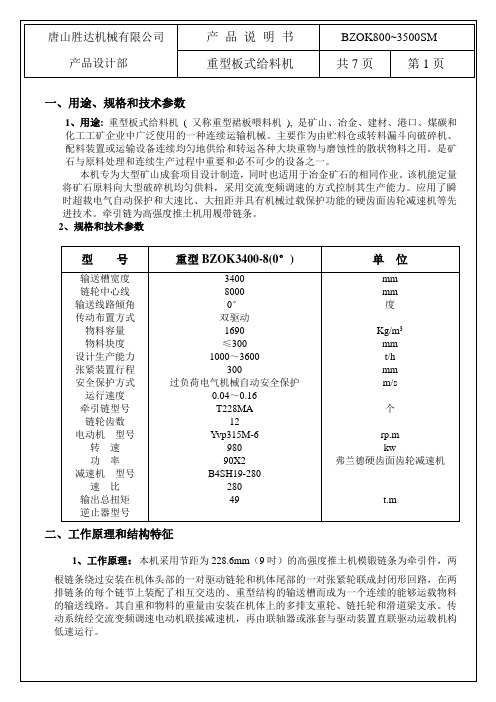
产品说明书
重型板式给料机
共7页
第4页
(2)运载机构的装配和调试:
链条装配后,通过尾部张紧轮进行预张,以消除各链节转动零件之间的间隙。但是在驱动链轮的下部则允许有15~20mm的松弛。(见附图1)
DISOCONT定量给料机简要操作说明(BV-H2061CH)

DISOCONT定量给料机简要操作说明(BV-H2061CH)DISOCONT VDB WEIGHFEEDER OPERATING INSTRUCTIONSDISOCONT VDB WEIGHFEEDER定量给料机简要操作说明书BV-H2061CH Copyright (版权所有):All rights reserved. Any reproduction of the manual, regardless method, without prior permission by SCHENCK PROCESS GmbH in writing, even by excerpt, is prohibited.版权所有,未经德国申克公司书面许可,任何人不得翻印或摘录。
Subject to change without prior notice.本资料变动其内容,不事先通知。
德国申克公司〔 SCHENCK PROCESS GmbH 〕总部地址:D-642273 Darmstadt, Germany销售部::+49-6151-32 1028 电子邮件:sales2.process@csd.de服务部:重工业部门〔基础材料和建筑材料〕:服务:+49-6151-32 2623 服务:+49-6151-32 3270重工业部门〔振动,冷却和干燥〕:服务:+49-6151-32 1075 服务:+49-6151-32 3096轻工业部门〔化工和食品工业〕:服务:+49-6151-32 2572 服务:+49-6151-32 1749工业称重部门〔轨道衡和汽车衡〕:服务:+49-6151-32 2448 服务:+49-6151-32 136924小时热线服务:+49-172 650 1700电子邮件:service3.process@csd.de备件供应部:电气备件:+49-6151-32 1758机械备件:+49-6151-32 3122: +49-6151-32 3632热线: +49-171 2251 195互联网地址: :// carlschenck.de名目:1.慨述:----------------------------------------------------第3页2.安全说明:------------------------------------------------第3页3.安全操作:------------------------------------------------第4页4.操作显示器使用说明:--------------------------------------第5页1.慨述:本简要说明书要紧讲述了对DISOCONT显示操纵单元的日常系统操作。
英文重型板式给料机说明书样本

Heavy-duty Apron Feeder2200×10000mmProduct Instruction Shenyang Mining Machinery Import & Export CorporationContentsage and useful scope2.technical character3.working principle and structure character4.installation,commissioning and test run5.operation rules and maintenance6.lubricating1、usage and useful scopeHeavy apron feeder widely used in mine,metallurgy,building material and coal departments. The machine usually is located under material bin and hopper with certain bin pressure. It can short distance transport kinds of materials with large density to crushing and sifting and transportation equipment equally and it is especially suitable for be used under primary crushing. It is not only suitable for treating big particle size material,but also thin particle size material. It can finish heavy-duty job in the bad environment and have good applicability to material particle size changing,temperature,viscosity,ice frost and rain snow effect,and it feeding quantity is right and equal. Installation of the machine can be horizontal,and also sloping. Max. inclined angle to up transporting is 23°。
PHL - 重型搬运器说明书

sealed bearing cartridge long life, easy maintenance
aluminum mounting plate
built-in rod compliance eliminates side load on cylinder piston rod, increasing life of unit
proximity switches are available for sensing end of travel
ISO cylinder for easy replacement
guideshafts chrome plated steel
optional stop collars and shock pads are adjustable
• Available in three bore sizes with many stroke lengths to fit your application requirements
• Built-in rod compliance eliminates side load on cylinder piston rod thus increasing life
on PHL8 units. 3) -M004-T002 options are mandatory for PHL4
& PHL8 units.
OPTION COMPATIBILITY CHART
LIFTER DESCRIPTION PHL4-5-M004 PHL6-5-M001 (STD) PHL6-5-M002 PHL6-5-M003 PHL6-5-M004 PHL8-5-M004
PHL02A
DJY611FE03-BW100-3板式给料机使用说明书

山宝牌SHAN BAO BRANDBW100-3板式给料机APRON FEEDER使用说明书OPERATING INSTRUCTIONK4240A.SM中华人民共和国THE PEOPLE S REPUBLIC OF CHINA 上海建设路桥机械设备有限公司SHANGHAI JIANSHE LUQIAO MACHINERY CO., LTD.目录一、前言 (1)二、用途 (1)三、规格和性能 (1)四、工作原理和结构概述 (2)五、安装和试运转 (3)六、润滑要求 (6)七、使用和维护 (6)八、易损零部件 (7)附件:基础图一、前言为了更好地发挥板式给料机的功能和效率,确保其正常工作,在安装该设备之前和使用过程中,请仔细参阅本说明书的内容,这将有助于为用户熟悉维护设备提供方便。
二、用途板式给料机可用于沿水平或倾斜方向由储仓向破碎机、输送机或其它工作机械传送各种块状或松散物料。
有轻型、中型和重型之分。
广泛用于矿山、冶金和水泥等行业,是原料处理或连续生产过程中不可缺少的设备,对运行大块和尖锐的物料尤为适宜。
BW100—3板式给料机按轻型设备设计,使用中可运送块度不大于500 mm,堆积密度 1.2 t/m3的石灰石、石膏等物料。
三、规格和性能宽度(mm)1000倾斜角度(°)0头、尾轮中心距(mm)3000输送速度(m/s)0.03~0.3输送量(t/h)18~180输送物料煤、石膏、石灰石、混合料等输送粒度(mm)≤500(对角线长度)电动减速机型号CHHM8-4190DB-AV-121 转速(r/min)150~1500额定功率(kW) 5.5速比i =121总重(kg)6213四、工作原理和结构概述本机由传动装置、机架、头部装置、运行部分及尾部装置等部件组成。
运行部分是本机的关键部件,由组成环路的牵引链条牵引,行走滚轮在轨道上行走,以达到运送物料的目的。
1.工作原理运行部分中输送槽板与牵引链条及承载机构分别相联接。
板式给料机使用说明书

中型板式给料机使用说明书目录1.用途和使用范围2.技术特性3.形式与参数4.结构5.输送原理6.安装调整和试机及维护保养7. 机器的润滑概述板式给料机为连续输送物料机械的一种,主要用于原矿一级破碎喂料,是沿水平或华侨的线段由贮料仓向破碎机、输送机或其他工作机机连续均匀地配给或转运各种松散物料的通用固定式给料机(图1)。
二、机型特点1、适用范围,对具有锋利棱角的和对输送机有强烈磨损性的物料或成件物品都可输送,规程密度不大于2400kg/m3。
还适宜输送小于400°C以下的高温物料。
2、牵引链条强度高,可作较长距离的输送,本产品最大输送长度可达18m。
3、布置灵活,板式给料机可左传动,也可右传动,可水平输送物料,也可倾斜输送物料。
其倾斜角0≤a≤25°。
用户可根据实际现场选定。
4、链板抗弯强度大,耐冲击。
5、运行平稳可靠、噪音小。
图1三、型式与基本参数图23.1型式中型板式给料机按承载物料的输送槽结构分为三种型式(图2)P型——输送槽承载板的纵剖面为平板形,适于沿水平或倾角小于或等于150输送块状物料L型——输送槽承载板的纵剖面为波浪形,适于沿水平面或倾角小于或等于250输送块状和颗粒状物料。
H型——输送槽承载板的纵剖面为圆弧形,适于沿水平或倾角小于等于250输送潮湿或和粘性物料。
3.2主要技术参数如下表表1注:1.链轮中心距为驱动链与拉紧链轮的中心距。
2.物料块度不得超过槽宽尺寸的一半。
3.机器总重是按给料机水平安装和不调速时在最大给料速度下设计的重量。
4.可根据用户需要设计适合现场工艺的非标产品四、结构板式给料机主要由以下若干部件组成:1、传动装置:传动装置包括电动机、减速机、联轴器、机架等。
2、头轮装置包括头部机座、主动轴、链轮、传动轴、前机架等。
3、链条4、链板5、尾轮装置:包括链轮、后机架、拉紧装置等。
6、支承与拦板7、中间架以上各部分出厂前己装配好,安装时根据总装图的形式及基础位置就位即可。
板式给料机里面的英文部件

板式给料机里面的英文部件Inside the Apron Feeder: Understanding the English Components.The apron feeder, also known as the plate feeder or the apron feeder type feeder, is a crucial piece of equipmentin various industrial processes. It serves to feed materials into a processing system at a controlled rate, ensuring smooth and efficient operations. Inside this feeder, several components work together to achieve this goal. Let's explore these components and their functions in English.1. The Frame: The frame of the apron feeder provides the structural support for the entire machine. It is usually made of heavy-duty steel to ensure durability and stability. The frame supports the weight of the conveyor belt, the motor, and other components, allowing them to function properly.2. The Conveyor Belt: The conveyor belt is the heart of the apron feeder. It runs continuously, carrying the material from the inlet to the outlet. The belt is usually made of a durable material like rubber or polyurethane, depending on the type of material being handled. The conveyor belt is driven by a motor, which is mounted on the frame.3. The Motor: The motor is the powerhouse of the apron feeder. It provides the necessary torque to drive the conveyor belt, ensuring it moves smoothly and at a consistent speed. The motor is usually located on one end of the frame and is connected to the conveyor belt through a gearbox or a direct drive system.4. The Gearbox: If the motor is not directly connected to the conveyor belt, a gearbox is used to transmit the power from the motor to the belt. The gearbox allows for adjustments in speed and torque, depending on the requirements of the process. It also helps in reducing the wear and tear on the motor and the belt.5. The Drive Rollers: The drive rollers are mounted on the frame and are responsible for driving the conveyor belt. They are usually made of a hard and durable material like steel or cast iron. The drive rollers engage with the teeth on the underside of the conveyor belt, pulling it forward.6. The Idler Rollers: In addition to the drive rollers, the apron feeder also has idler rollers. These rollers are positioned along the length of the conveyor belt,supporting it and keeping it taut. They help in reducing friction and wear on the belt, ensuring it lasts longer.7. The Tensioning Device: To maintain the propertension on the conveyor belt, a tensioning device is used. This device, usually a spring-loaded or hydraulic mechanism, adjusts the tension on the belt, keeping it taut but nottoo tight. This prevents slippage and ensures consistent material feed.8. The Inlet and Outlet Chutes: The inlet chute guides the material onto the conveyor belt, ensuring it is evenly distributed. The outlet chute, on the other hand, directsthe material off the belt into the next processing stage. Both chutes are designed to minimize spillage and maximize material transfer efficiency.9. The Control System: The control system of the apron feeder monitors and regulates the operation of the machine. It controls the speed of the conveyor belt, the tensioning device, and other critical parameters. The control system can be either manual or automatic, depending on the requirements of the process.10. Safety Features: To ensure the safety of operators and maintenance personnel, the apron feeder is equipped with various safety features. These include guards to protect against falling material, emergency stop buttons, and sensors to detect obstructions or overloads.In conclusion, the apron feeder is a complex machine with multiple components working together to achieve its purpose. Each component plays a crucial role in ensuring smooth and efficient material handling. From the frame that supports the entire structure to the control system thatregulates its operations, each component is designed to perform a specific function, contributing to the overall efficiency of the apron feeder.。
全封闭重型板式给料机说明书

驱动链轮为多齿的合金铸钢材质,齿廓经表面淬火硬化处理,具有良好的强度和耐磨性。张紧轮采用无齿形结构和外踏面硬化处理工艺,达到了减少运转中的振动和牵引链磨损的目的,对整机运行的平稳性有显著作用。
驱动轴和张紧轴采用40Cr或42CrMo锻钢和调质热处理。轴承座都是铸钢材质与迷宫式密封结构,使用效果好。主轴承均采用自动调心滚子轴承与定时供脂装置,因而具有润滑和密封性良好、使用寿命长、运行阻力小和维护简便的特点。螺旋张紧机构能简便有效地控制牵引链条的预张力和调整运载机构的跑偏。
度
Kg/m3
mm
t/h
mm
运行速度
牵引链型号
链轮齿数
电动机型号
转速
功率
减速机型号
速比
输出总扭矩
逆止器型号
0.01~0.084
T228MA
9
Yvp280M-6
980
55
KDAB630-400
400
20
kw
硬齿面齿轮减速机
t.m
二、工作原理和结构特征
1、工作原理:本机采用节距为228.6mm(9吋)的高强度推土机模锻链条为牵引件,两根链条绕过安装在机体头部的一对驱动链轮和机体尾部的一对张紧轮联成封闭形回路,在两排链条的每个链节上装配了相互交迭的、重型结构的输送槽而成为一个连续的能够运载物料的输送线路。其自重和物料的重量由安装在机体上的多排支重轮、链托轮和滑道梁支承。传动系统经交流变频调速电动机联接减速机,再由涨套与驱动装置直联驱动运载机构低速运行。
(7)过负荷自动保护:
给料机在运行过程中,如果发生大块物料或异物出现堵塞的情况,为了防止电动机、减速机传动部件与驱动装置的零部件发生过载损坏。在控制电路中应设计过载电气自动保护线路和电子元器件。
- 1、下载文档前请自行甄别文档内容的完整性,平台不提供额外的编辑、内容补充、找答案等附加服务。
- 2、"仅部分预览"的文档,不可在线预览部分如存在完整性等问题,可反馈申请退款(可完整预览的文档不适用该条件!)。
- 3、如文档侵犯您的权益,请联系客服反馈,我们会尽快为您处理(人工客服工作时间:9:00-18:30)。
Heavy-duty Apron Feeder2200×10000mmProduct Instruction Shenyang Mining Machinery Import & Export CorporationContentsage and useful scope2.technical character3.working principle and structure character4.installation, commissioning and test run5.operation rules and maintenance6.lubricating1、usage and useful scopeHeavy apron feeder widely used in mine, metallurgy, building material and coal departments. The machine usually is located under material bin and hopper with certain bin pressure. It can short distance transport kinds of materials with large density to crushing and sifting and transportation equipment equally and it is especially suitable for be used under primary crushing. It is not only suitable for treating big particle size material, but also thin particle size material. It can finish heavy-duty job in the bad environment and have good applicability to material particle size changing, temperature, viscosity, ice frost and rain snow effect, and it feeding quantity is right and equal. Installation of the machine can be horizontal, and also sloping. Max. inclined angle to up transporting is 23°。
2、technical character:Specification-----------------------------------------2200X9944mmWidth of chain plate-------------------------------------2200 mmThe distance from sprocket shaft centerline to take up shaft centerline---------------9944 mmFeeding speed-------------------------------------0.01∽0.067m/sCapacity-------------------------------------100~650t/h Particle size-------------------------------------≤1.0x1.0x1.2mAdjustable distance of take up device-----------------------------700 mmInclined angle to up transporting---------------------------------20°motor:Type-----------------------------------YP2280M-6Power-----------------------------------55KWRevolution -----------------------------------980r/min reducer:Planet and orthogonal typeTotal speed ratio---------------------------------610 3、working principle and structure characterThe machine running come true by that motor drives sprocket shaft rotating through coupling and reducer, and at the same time the mesh between sprocket gear and pin shaft of chain makes chain plate moving along straight line. Chain plates are supported by thrust wheels and carry wheels installed on the frame, and adjusting take up device makeschain and sprocket mesh, thereby the machine finish the aim of transporting material to crusher.Heavy-duty apron feeder (see drawing 1) include drive unit1, chain plate device2, take up device3, main shaft device4, frame5, thrust wheel6, carry sprocket7, etc. and its main characters are as follows: 3.1 drive unit (see drawing 2) include motor1, coupling2, orthogonal reducer3, planet reducer4, torque lever5, locked disc6, etc. the unit adopts orthogonal shaft fulcrum float type, the sleeve of main shaft is installed in output shaft of planet reducer, and connection between them is through locked disc. The structure character is low weight and big speed ratio. Because of adopting fulcrum float type, to reduce additional bend moment to shaft caused by installation error, and to increase using life of transmission and easy for dismounting.3.2 chain plate device (drawing 3) include: pan plate1, chain element2, etc. pan plate adopts single arc join type and is made by low alloy steel plate. Its character is high strength, wearproof and no leakage. Chain element adopt tank chain and its character is small pitch error, calm running, high strength, and no lubricating.3.3 take up device(drawing 4) is screw lever take up mechanism and it include: shaft1, two carry wheels2, rolling bearing3, bearing housing4, complex spring5, and take up screw6, etc. carry wheel is fixed on the shaft through sleeve, roller bearing and bearing housing are installedat the two ends of shaft and therein bearing housing is installed at two sides of frame. Take up device is used for straining chain and adjusting horizontal position of chain. Carry wheel act guiding and supporting chain plate. Complex spring act compact function.3.4 main shaft device(see drawing 5) include: shaft1, bearing housing2, sprocket3, supporting wheel4, and bearing housing5, etc. the aim of transporting material is to come true by that two sprockets on shaft draw chain plate to run. The device character is easy dismounting and maintenance because the connection between sprocket and supporting wheel adopts expanding sleeve connection, and main shaft is installed in the output shaft in reducer.3.5it is Ⅰ-shape structure made of steel plate, several reinforcement plates are welded between top and bottom alate plates. The two Ⅰ-shape main beams are welded together through channel steel and Ⅰ-shape steel, which structure is firm and calm.3.7 thrust wheel(drawing 7)include: pedestal(1), rolling bearing(2), shaft(3), roller(4), press cover(5), seal ring(6) etc. it is used for supporting chain to prevent chain plate from forming large flexivity caused by load and self-weight. And it can make chain normal running and undertaking some material impact and pressure from bin, and at the same time it can prevent chain form offset.3.8 carry sprocket:(drawing 8)it include: pedestal(1), shaft(2)shim(3), rolling bearing(4), support wheel(5) end cover(6), cover(7) etc. it is used for supporting chain plate to prevent chain plate from forming too large flexivity to effect normal running.4. Installation, commissioning and test runBefore installation, components should be cleaned necessarily, and installation tools should be prepared well.4.1 installation of the frame: The frame usually is mounted the base under bin or and hopper, and it is jointed through pre-embedded bolt. If no bolt, there should be pre-embedded steel plate on the base. The frame would be welded on the pre-embedded steel plate, if height need to be adjusted, shim can be used, but shim must be welded on the pre-embedded steel plate.4.2 Sprocket shaft device and take up device are hanged on the frame, after installing connection bolts, adjust bearing housing to make the verticality and levelness between sprocket shaft line and frame centerline not more than 1/1000 of its bearing span. When take up device is mounted, be sure that the parallelism between take up shaft centerline and horizontal plane is not more than 0.5/1000 of its bearing span. On the base of two shaft lines, the difference of two diagonals should be not more than 1/1000.through adjusting reach requirements later, sprocket device and take up device would be fixed on the frame. when installing thrust wheel, parallelism of shaft centerline of thrust wheelon lengthways and cross direction cannot exceed 1, and it can be adjusted by adding pad.4.3 motor and reducer would be mounted on the main shaft, and would be tightened by locked disc, and each bolt tightening moment of locked disc is 470N.M.4.4 Adjust screw of take up device to make it on the position of min. travelling point. Make chain plate device level higher by putting steel plate or channel steel under frame till side plate of chain plate is accordance with carry sprocket in height. Raise an end of chain plate to let chain plate slide from the end to other. After moving for a certain distance, the other end chain plate is jointed. The chain movable joint as same as others adopt pin shaft connection, but combining clearance between pin shaft of movable joint and chain element is looser than others. To knock by hand hammer can make pin shaft of movable joint installed into chain element, and make marks on movable joint easy for repairing and for dismounting. After the second section of chain plate is installed, by above method, lift chain continuously till two ends outer chain plate length is same, then lift two-end chain plate through steel wire rope to finish chain plate butt.4.5 adjust screw in take up device and tension chain plate to make it in good state. Again check if installation is right and connection bolts are tightened well and in that reducer and lubricated section is filledwith lubricant oil, and check if junction for motor and electric device is right. After all are checked, can start machine and run for 2 hours without load.4.6 no-load test run should reach the following requirements:4.6.1 running is normal, and rotary components turn freely and no blocking and no knocking.4.6.2 sealed position in lubricating components is no leakage.4.6.3 no loosing to tensioning parts, especially connection bolt between chain plate and chain element never loose.4.6.4 top and bottom rollers should turn freely and two arc join section of chain plate should be not less than 10mm.4.6.5 rising temperature cannot exceed 30℃ and max. temperature of bearing can not exceed 60℃.4.7 after no load test run is up to standard, test run with load is required before putting into production. Time of test run can be decided according to actual condition but continuous test run cannot be less than 2 hours. Load should be added till max. and check it according to stipulated data in drawing, after certificate the machine can be used.5.operation rules and maintenance5.1 all the time keep certain thickness material on chain plate during the machine is running, material thickness can not be less than 500mm, and it is not permitted that material is put into chain plate directlyon the discharging empty state. If no avoidance on chain plate should be paved a layer of broken material before discharging to prevent from direct impacting chain plate. When big block of material stop up, it is not permitted to adopt demolishing.5.2 after the machine is installed, the distance from outlet to chain plate should be not less than 1.5-2 times of biggest material. Should keep 8-13mm clearance between protection plates and baffles on the two sides of chain plate to avoid material outflow and friction. The distance from bottom edge of protection plate to surface of chain plate should keep 5-10mm.should keep 350-500mm clearance from shaft centerline of take up device to back wall of bin for easy maintenance and dismounting.5.3 when chain pitch fray exceed 7mm, should change new chain.5.4when knock down expanding sleeve, firstly loosing all the screws but no taking off all the screws, only taking off galvanized screw and washer, again knocking head section to make sleeve loosing, then taking off screw and sleeve is disassembled.5.5 when installing expanding sleeve, should clean primary installation surface and paint a layer grease, then tighten screw by moment spanner.5.6 when installing rolling bearing of main shaft device, should be sure that the min. diameter direction clearance is about 0.08mm, and that reducing of diameter direction clearance should be between 0.09-0.11. The min. clearance to rolling bearing of take up device should reachabout 0.55, and that reducing of diameter direction clearance should be between 0.06-0.07.5.7 when changing chain plate, the bolts used for connecting chain plate and chain should be painted anaerobic glue to prevent loosing, and each bolt tightening moment is 750-900N.M.5.8 operator should master the structure principle of machine, and before operation every time should check if all the components are normal and bolts for chain plate are loose. After all are checked, the machine can be started.5.9 right lubricating bearing and reducer and changing new grease timely.5.10often check chain plate working state, should keep chain good loosing. If founding offset, adjust it by take up device.5.11if there appear abnormal noise or fault, the machine should be stopped at once. In time find out reason and get rid of fault.5.12timely check and repair the machine, and in time change wearing components.6.lubricating6.1 lubricating points include reducer, sprocket shaft, thrust wheel and take up device.6.2the lubricant for bearing adopt ZG-4 Ca-radical lubricant grease(GB491-65), for reducer had better adopt S-P90# industry gearoil(apply to dry environment) or S-P90# industry gear oil(apply to wet environment).。
