SMC电气比例阀中文手册
SMC ITV系列电动比例阀说明书加说明

E/P REGULATORMODEL NAMEITV1000, ITV2000, ITV3000 series ITV1000, ITV2000, ITV3000 seriesSeriesContentsP1 Safety instructions P2 Handling precautions P3-4 Wiring method P5-6 Setting methodP7 Key locking functionP8 Setting of min. pressure, max. pressure and switch output P9 Mode of switch outputP10 Setting of preset pressure P11 Reset functionP11 Error indicating function P12 Detail setting mode P13 Gain settingP13-14 Sensitivity setting P14 Zero clear P15 Initialize P15-16 LED displayP16URL MANUALCONTENTS CONTENTSThese safety instructions are intended to prevent a hazardous situation and/or equipment damage. These instructions indicate the level of potential hazard by labels of “CAUTION ” “WARNING ”, or “DANGER ”. To ensure safety, be sure to observe ISO 4414, JIS B 8370 and other safety practices.■Explanation of label△! WARNING WARNING Operator error could result in serious injury or loss of life. △!CAUTION CAUTIONOperator error could result in injury or equipment damage.△!①comp The compatibility atibility of pneumatic equipment is the responsibility of the person who who designs designs designs the pneumatic system or decides its specifications. the pneumatic system or decides its specifications.the pneumatic system or decides its specifications. Since the products specified here are used in various operating conditions, their compatibility for the specific pneumatic system must be based on specifications or after analyses and/or tests to meet your specific requirements. The expected performance and safety assurance will be the responsibility of the person who has determined the compatibility of the system. This person should continuously review the suitability of all items specified, referring to the latest catalog information with a view to giving due consideration to any possibility of equipment failure when configuring a system.②Only trained personnel should operate pneumatically operated machinery andequipment.equipment.Compressed air can be dangerous if an operator is unfamiliar with it. Assembly, handling or repair of pneumatic systems should be performed by trained and experienced operators.③Do not service machinery / equipment or attempt to remove components until safety is confirmed.safety is confirmed.A. Inspection and maintenance of machinery / equipment should only be performed once safetyof personnel and equipment is confirmed.B. When equipment is to be removed. Stop supplied air, exhaust the residual pressure, verify the release of air, turn the power off and confirm safety before performing maintenance.C. Before machinery / equipment is restarted, ensure safety before applying power.④Contact Contact SMC if the product is to be used in any of the following conditions. SMC if the product is to be used in any of the following conditions. SMC if the product is to be used in any of the following conditions.A. Conditions and environments beyond the given specifications, or if product is usedoutdoors.B. Installation on equipment in conjunction with atomic energy, railway, air navigation, vehicles, medical equipment, food and beverages, recreation equipment, emergency stop circuits, clutch and brake circuit in press applications, or safety equipment.C. An application which has the possibility of having negative effects on people, property, or animals requiring special safety analysis.△!If power to this product is cut off due to a power failure, etc. when it is in a controlled state, residual pressure will be retained temporarily. Handle carefully when operating with output pressure released to the atmosphere, as air will continue to flow out.If supply pressure to this product is interrupted or shut off, while the power is still on, the internal solenoid valve will continue to operate and a humming noise may be generated. Since the life of the product may be shortened, shut off the power supply also when supply pressure is interrupted or shut off.The optional cable connector is a 4 wire type. When the monitor output (analogue output or switch output) is not being used, prevent it from touching the other wires as a malfunction could occur.This product is adjusted for each specification at the time of shipment from the factory. Avoid careless disassembly or removal of parts, as this can lead to malfunction.△!Take the following steps to avoid malfunction due to noise.1)Install a line filter etc. to the AC powerline to reduce / eliminate power supplynoise.2)Avoid malfunction due to noise byinstalling this product and its wiringaway from strong electric fields, such asthose of motors and power line, etc.3)Be sure to implement protective measuresagainst load surge for induction loads(solenoid valves, relays etc.).4)Turn off the power supply beforeinstalling or removing the connector.Please note that the right angled cable connector does not rotate and is limited to only one entry direction.△!① Proceed carefully, as incorrect wiring can cause damage. ② Use DC power supply with sufficient capacity and a low ripple. ③ Turn off the power supply to remove and insert the connector. ④ Never turn the right angled type connector as it is not designed to turn.Note) The wire color isfor when optional cable is used.Wiring Wiring diagram (diagram (diagram (Power supply and input signal)Power supply and input signal)Power supply and input signal)Current/Voltage type(ITV※0※※-0、ITV※0※※-1、ITV※0※※-2、ITV※0※※-3)Preset input type(ITV※0※※-4)1 Brown Power supply 2 White Input signal 3 Blue GND(COMMON) 4 Black Monitor outputWiring diagram Wiring diagram((Monitor output Monitor output))△!When the monitor output is not being used, prevent it from touching the other wires as this can cause a malfunction.△!① If the incorrect key is pressed or incorrect information is displayed during setting, power must be shut off and the procedure started again.② It is recommended that the settings are changed without supply pressure. The product operates immediately maximum and minimum pressures are set and the S-key is pressed.③ It is recommended that the minimum pressure is output when air is supplied to the inlet, even if the input signal has not been entered.④ Output pressure from this product and state of operation are changed by changing of each setting and function. Each setting and function should be operated by trained and experienced operator.Flow of the setting(Note 1): Please refer to each contents about operation methode.(Note 2): The function of the setting of preset pressure is preset input typeonly.(Note 3): The function of the setting of switch output is switch output typeonly.设置预设压力设置最小压力设置最大压力设置选择输出详细设置增益灵敏度△!The keys are locked after turning the power on and can not be operated. Unlocking the keys(DEFAULT VALUE: 0%)(Note 2): The pressure of less than 0% is not output, even if F_1 is adjustedto less than 0%. (Note 3): F_2 is adjustable in a range from 10 to 120% of the rated value.(DEFAULT VALUE: 100%) (Note 4): Do not input the signal as like output the pressure of more than 100%.Please use in a range of rating. (Note 5): The difference between F_1 and F_2 is adjustable in a range of 10% ofthe rated value.(Note 6): The adjustment like making the relation of F_1>F_2 is not available.设置最小气压、最大气压以及选择输出F 1调整范围在-20%~90%之间如果F 1设置低于0%则无输出F 2调整范围在10%~120%之间不要将输入信号设置像输出信号超过100%,请设置在合理范围F 1和F 2不同在于设定值10%的范围The following operation types are available by setting P_1 and P_2.Note). This function is available for monitor output: switch output type (ITV※0※※-※2 and ITV※0※※-※3). ■ P_1<P_2 : ■P_1≧P_2 : Window comparator modeHysteresis mode■ P_1=P_2=0 : Out of range mode(The switch output turns on when set pressure is achieved.)输出模式的选择(DEFAULT VALUE: 0%)Reset method Reset content Item Reset content Application model F_1 0%F.S. Current・Voltage input type F_2 100%F.S. Current・Voltage input type P_1、P_2 100%F.S. Switch output type P_1~P_4 0%F.S. Preset input type (Note): Gain (GL) and sensitivity (SL) are not reset.Reset function Reset functionNormal operation does not require the adjustment of gain. This product can change the response with this gain setting.When the gain is changed to more larger, the response become quickly, but there is a possibility that stability is lost. Gain setting Gain settingRelation between setting of gain and response timeNormal operation does not require the adjustment of sensitivity.When the sensitivity is changed, the correction operation of pressure changes. When the sensitivity is changed to sharp, the hunting of pressure might be occurred. And, when the sensitivity is changed to dull, there is a possibility that staggering of gradual pressure occur, because the pressure correction become lower.Sensitivity setting Sensitivity settingThe display can be set to zero again by executing "zero clear".When "zero clear" is executed with residual pressure in the secondary piping, the pressure is assumed to be zero. Please execute the operation of "zero clear" with the supply pressure is intercepted, and the piping of the second side removed. is not executed."Initialize" is a function to return all the settings that the internal control constant are included to an initial value. Please execute "initialize" only when the error is displayed and this product doesn't operate at all. Please execute the "reset" function, when you want to return the pressure setting and the switch setting to an initial value.No Key operation LED Display① Unlock keys (refer to P8)② Press S-key for 2 seconds or more, then go to detail setting mode.Initialize InitializeThe range of the LED pressure display is different according to the pressure range and the unit of the display.unit ITV※01※ ITV※03※ ITV※05※ ITV209※ MPa 。020~.120 。100~.600 。180~.A80 - Kgf/cm 2 0。20~.120 1。00~6.00 1。80~A.80 - bar 0。20~.120 1。00~6.00 1。80~A.80 - PSI 3。0~18.0 14。0~84.0 -26~156 - kPa -20~120 -100~600 -180~A80 16~-96(note1):The mark "。" is blinking the decimal point, and it is shown a minus. (note2):When the digit overflows, the following of "9" are substituted by "A".(example: The following of 999(kPa) are displayed as A00(kPa), and it shows 1000 kPa.)(note3):When the display exceeds the lower bound value, "" is displayed. (note4):When the display exceeds the upper bound value, "" is displayed.This operation manual refers to all standard types and is partially applicable to special models.This operation manual is subject to change without prior notice or any obligation on the part of the manufacturer.LED LED display display。
SMCITV系列电气比例阀ITV3050-314CL使用注意事项

SMCITV系列电气比例阀ITV3050-314CL使用注意事项SMC电气比例阀ITV3050系列正品保障;原装正品SMC电气比例阀ITV3050系列到货上海电气比例阀ITV1000·2000·3000系列;SMC电气比例阀ITV3050系列正品保障SMC电气比例阀是一种新型的液压控制装置。
在普通压力阀、流量阀和方向阀上,用比例电磁铁替代原有的控制部分,按输入的电气信号连续地、按比例地对油流的压力、流量或方向进行远距离控制。
一般具有压力补偿性能,输出压力和流量可以不受负载变化的影响。
该比例阀是一种按输入的电信号连续地、按比例地控制液压系统的液流方向、流量和压力的阀类。
普通阀只能通过预调的方式对液流的压力、流量进行定值控制。
但是当设备机构在工作过程中要求对液压系统的压力、流量参数进行调节或连续控制,例如,要求工作台在工作进给时按慢、快、慢连续变化的速度实现进给,或按一定精度模拟某个控制曲线实现旅力控制,普通液压阀则实现不了。
比例阀的输出流量与气体性质,有效通气面积,阀门前后两端的气压压差有关,通过比例阀的气体绝大部分为氧气和空气(N2,O2N_2,O_2N2?,O2?),均为双原子气体分子,气体动力学性质基本相同,在模型中可以不用考虑气体自身性质的影响。
动作原理输入信号增大时,1供气电磁阀变为ON,2排气电磁阀变为OFF。
因此,供给压力通过1供气电磁阀作用在3先导室。
并且,3先导室的压力上升,作用在4膜片上面。
由此结果,与4膜片连动的5供气阀打开,一部分供给压力成为输出压力。
此输出压力,通过7压力传感器反馈到8控制回路。
在此,会进行压力调节,直至输出压力与输入信号成比例,因此,可以稳定地得到与输入信号成比例的输出压力。
高速响应型托架同包出厂。
无负载时的压力响应,响应时间约为0.1sec。
取决于使用环境,非保证值。
输入信号0%时,控制排气电磁阀使输出压力为零。
这种情况下可能会产生噪音,但并非异常。
SMC系列产品使用说明书
5.3对于1-PC和牙嵌式驱动空心轴的电动装置其安装方法是:起吊电动装置使1-PC空心轴孔与阀杆和键配合装入,牙嵌驱式空心轴上的牙嵌与阀门上阀杆螺母的牙嵌对准。用螺栓将电动装置与阀门紧固可靠。
4.1专用电动机:适合阀门的载荷特性和使用工况,型号YLT。
4.2减速机构:用于传递和增大电动机的动力。每个机座产品均有3~5种速比的蜗轮副和若干电机齿轮与蜗杆轴齿轮传动比的齿轮副,因而可获得较大的输出转速范围。
4.3驱动空心轴:它是电动装置的动力输出部件,有2-PC、1-PC、牙嵌式三种型式,结构可见(图10)~(图12)
2.基本技术参数
产品符合JB/T8528-1997《普通型阀门电动装置技术条件》
2.1动力电源:380V、50Hz三相正弦交流电(根据用户要求,某些规格可提供使用单相220V电源的电动机)。
2.2外壳防护等级:SMC-04、03 IP67
SMC-00~5 IP65
2.3使用环境温度:-20℃~40℃;-20℃~60℃(根据用户订货要求)
G·L·SW各列转体上触点的相对位置可任意布置,即同一列上的触点可以全部为“OFF”型式或为“OFF”“ON”两种型式。(最常用的是“OFF”“ON”的布置型式)。
G·L·SW中间的两列转体触点开关可做为阀门某两个中间位置的信号输出,也可将其调整到与两边的转体同步动作。
(图17)为典型控制原理时触点开关的布置型式。
电气接线程序及注意事项:
7.1确认电源电压与电动机使用电压相同。
SMC SZ3000-TF2Z507EN 5口阀门式压力调节器说明书
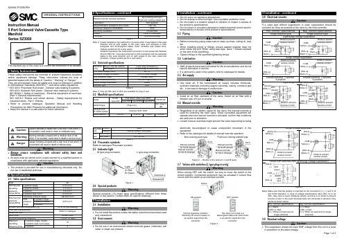
Instruction Manual5 Port Solenoid Valve/Cassette Type ManifoldSeries SZ3000The intended use of this valve is to control the movement of an actuator.1 Safety InstructionsThese safety instructions are intended to prevent hazardous situationsand/or equipment damage. These instructions indicate the level ofpotential hazard with the labels of “Caution,” “Warning” or “Danger.”They are all important notes for safety and must be followed in additionto International Standards (ISO/IEC) *1), and other safety regulations.*1) ISO 4414: Pneumatic fluid power - General rules relating to systems.ISO 4413: Hydraulic fluid power - General rules relating to systems.IEC 60204-1: Safety of machinery - Electrical equipment of machines.(Part 1: General requirements)ISO 10218-1: Robots and robotic devices - Safety requirements forindustrial robots - Part 1: Robots.•Refer to product catalogue, Operation Manual and HandlingPrecautions for SMC Products for additional information.• Keep this manual in a safe place for future reference.Caution Caution indicates a hazard with a low level of risk which, ifnot avoided, could result in minor or moderate injury.Warning Warning indicates a hazard with a medium level of riskwhich, if not avoided, could result in death or serious injury.Danger Danger indicates a hazard with a high level of risk which, ifnot avoided, will result in death or serious injury.Warning•Always ensure compliance with relevant safety laws andstandards.•All work must be carried out in a safe manner by a qualified person incompliance with applicable national regulations.Caution•The product is provided for use in manufacturing industries only. Donot use in residential premises.2 Specifications2.1 Valve specificationsFluid AirInternal pilotoperatingpressurerange [MPa]2 position single 0.15 to 0.72 position double 0.1 to 0.73 position 0.2 to 0.74 position dual 3 port 0.15 to 0.7External pilotpressurerange [MPa]Operating pressure range -100 kPa to 0.7Pilotpressurerange2 position single0.25 to 0.72 position double3 positionAmbien and fluid temperature [˚C]-10 to 50 (No freezing)Flow rate characteristicsRefer to catalogueResponse timeDuty cycle Contact SMCMinimum operating frequency 1 cycle / 30 daysMaximumoperatingfrequency [Hz]2 position single, double,4 position dual 3 port valve103 position 32 Specifications - continuedManual override (manual operation)Non-locking push typePush-turn locking slotted typeLubrication Not requiredImpact/Vibration resistance [m/s2] Note 150 / 30Enclosure (based on IEC60529) IP40Mounting orientation UnrestrictedWeight Refer to cataloguePilot type Common exhaustTable 1.Note 1) Impact resistance: No malfunction occurred when it was tested in the axialdirection and at right angles to the main valve and armature in bothenergized and de-energized states. Each condition was tested once.(Values quoted are for a new valve).Vibration resistance: No malfunction occurred in a one-sweep test between45 and 2000 Hz. Test was performed in both energized and de-energizedstates in the axial direction and at right angles to the main valve andarmature. (Values quoted are for a new valve).2.2 Solenoid specificationsElectricalentryPlug-in, EX140, EX510 L type plug connector (L)Non plug-in M type plug connector (M)Coil rated voltage [VDC] 24, 12Allowable voltage fluctuation ±10% of rated voltageCoil insulation class Contact SMCPower consumption [W] 0.6 (With light: 0.65)Surge voltage suppressor DiodeIndicator light LEDTable 2.Note 1) Only 24 VDC and 12 VDC are available for plug-in use.2.3 Manifold specificationsModelD-subType 60FFlat ribbon cable type 60P#SS5Z3-60Type 60P Type 60PG Type 60PHManifold type Plug-in (L)Non plug-in(M)1(P:SUP)/3/5(R: EXH) systemCommon SUP, EXHValve stations 2 to 20 2 to 16 2 to 8 2 to 204(A)/2(B)portLocation ValveDirection Lateral, upward, downwardPortsize1(P), 3/5(R) C84(A), 2(B) C4, C6, M5Table 3.2.4 Pneumatic symbolsRefer to catalogue Pneumatic symbols.2.5 Indicator lightM type plug connector L type plug connectorFigure 1.2.6 Special productsWarningSpecial products (-X) might have specifications different from thoseshown in this section. Contact SMC for specific drawings.3 Installation3.1 InstallationWarning•Do not install the product unless the safety instructions have been readand understood.3.2 EnvironmentWarning•Do not use in an environment where corrosive gases, chemicals, saltwater or steam are present.3 Installation - continued•Do not use in an explosive atmosphere.•Do not expose to direct sunlight. Use a suitable protective cover.•Do not install in a location subject to vibration or impact in excess ofthe product’s specifications.•Do not mount in a location exposed to radiant heat that would result intemperatures in excess of the product’s specifications.3.3 PipingCaution•Before connecting piping make sure to clean up chips, cutting oil, dustetc.•When installing piping or fittings, ensure sealant material does notenter inside the port. When using seal tape, leave 1 thread exposedon the end of the pipe/fitting.•Tighten fittings to the specified tightening torque.3.4 LubricationCaution•SMC products have been lubricated for life at manufacture, and do notrequire lubrication in service.•If a lubricant is used in the system, refer to catalogue for details.3.5 Air supplyWarning•Use clean air. If the compressed air supply includes chemicals,synthetic materials (including organic solvents), salinity, corrosive gasetc., it can lead to damage or malfunction.Caution•Install an air filter upstream of the valve. Select an air filter with afiltration size of 5 μm or smaller.3.6 Manual overrideWarning•Regardless of an electric signal for the valve, the manual override isused for switching the main valve. Since connected equipment willoperate when the manual override is activated, confirm that conditionsare safe prior to activation.•Locked manual overrides might prevent the valve responding to beingelectrically de-energised or cause unexpected movement in theequipment.•Refer to the catalogue for details of manual override operation.Non-locking push type Push-turn locking slotted typeFigure 2. – Position is the same on L and M types3.7 Valves with switches (L type plug-in only)WarningWhen turning OFF with the switch, be sure to move the switch to thelocked position. Connected equipment may be actuated if current flowoccurs with the switch at an improper position.ON position OFF positionNormal operating condition.Switching off valve is based onan electric signal from theconnector.The valve coil is kept in adeenergized state even when thereis an electric signal from theconnector.Figure 3.3 Installation - continued3.8 Electrical circuitsCautionIf a valve type without suppression is used, suppression should beprovided as close as possible to the valve by the host controller.Pos. common specifications Neg. common specificationsSingle solenoid type Single solenoid typeLight/surge voltage suppressorSurge voltage suppressorDouble solenoid, 3 position,4 positionDouble solenoid, 3 position,4 positionLight/surge voltage suppressorSurge voltage suppressorValves with switches (with light/surge voltage suppressor)-Figure 4.Note) Make sure that the polarity is matched on the connector’s (+), (-) and A, Band COM indicators. In case of voltage specifications other than 12 or 24VDC, take care to avoid mistaking polarity, as there is no diode to preventreverse current. In the event that lead wires are connected in advance, theywill be as shown below.Pos. common specifications Neg. common specificationsA (-): BlackCOM (+): RedB (-): White (no lead wire forsingle solenoid)A (+): BlackCOM (-): RedB (+): White (no lead wire for singlesolenoid)3.9 Residual voltageCaution•The suppressor arrests the back EMF voltage from the coil to a levelin proportion to the rated voltage.ORIGINAL INSTRUCTIONSSol.AManual overridefor Sol.B (Green)Manual overridefor Sol.A (Orange)Sol.BSol.AManual overridefor Sol.B (Green)Manual overridefor Sol.A (Orange)Sol.BSolenoid ASolenoid BLightA: RedB: GreenDiode to preventreverse currentCoilCOMRed (+)[SOL.a]Black (-)LED(Red)Diode to preventreverse currentCoilCOMYellow (-)[SOL.a]Black (+)LED(Red)Diode to preventreverse currentCoilCOMRed (+)[SOL.a]Black (-)Diode to preventreverse currentCoilCOMYellow (-)[SOL.a]Black (+)Diode to preventreverse currentCoil[Sol.b]White (-)[SOL.a]Black (-)LED(Red)COMRed (+)CoilLED(Green)Diode to preventreverse currentCoil[Sol.b]White (-)[SOL.a]Black (-)COMRed (+)CoilDiode to preventreverse currentCoil[Sol.b]White (+)[SOL.a]Black (+)LED(Red)COMYellow (-)CoilLED(Green)Diode to preventreverse currentCoil[Sol.b]White (+)[SOL.a]Black (+)COMYellow (-)CoilSwitchCoil[Sol.b](-)[SOL.a](-)SwitchCoilCOM(+)LED(Green)LED(Red)3 Installation - continued•Ensure the transient voltage is within the specification of the hostcontroller.•In the case of a diode, the residual voltage is approximately 1 V.•Valve response time is dependent on surge suppression methodselected.3.10 Countermeasure for surge voltageCaution•At times of sudden interruption of the power supply, the energy storedin a large inductive device may cause non-polar type valves in a de-energised state to switch.•When installing a breaker circuit to isolate the power, consider a valvewith polarity (with polarity protection diode), or install a surgeabsorption diode across the output of the breaker.3.11 Extended period of continuous energizationWarningIf a valve will be continuously energized for an extended period of time,the temperature of the valve will increase due to the heat generated bythe coil assembly. This will likely adversely affect the performance of thevalve and any nearby peripheral equipment. Therefore, if the valve is tobe energized for periods of longer than 30 minutes at a time or if duringthe hours of operation the energized period per day is longer than the de-energized period, we advise using a 0.4 W or lower valves, such as theSY series, or a valve with power-saving circuit.3.12 Effect of back pressure when using a manifoldWarning•Use caution when valves are used on a manifold because an actuatormay malfunction due to back-pressure.•Special caution must be taken when using 3 position exhaust centrevalve or when driving a single acting cylinder. To prevent amalfunction, implement counter measures such as using a single EXHspacer assembly or an individual exhaust manifold.3.13 Manifold electrical wiring specificationsRefer to catalogue for manifold electrical wiring specifications.3.14 How to use plug connectorRefer to catalogue for additional information.3.14.1 Attaching and detaching connectorsFigure 5.3.14.2 Crimping of lead wires and socketsFigure 6.3.14.3 Attaching and detaching lead wires with socketsFigure 7.3 Installation - continued3.15 Common connector assembly wiringRefer to catalogue for additional information.Figure 8. Common connector assembly wiring3.16 Exhaust restrictionCautionSince the SZ series is a type in which the pilot valve exhaust joins themain valve exhaust inside the valve, care must be taken that the pipingfrom the exhaust port is not restricted.3.17 Use as a 3-port valveCautionThe SZ3000 series valves can be used as normally closed (N.C.) ornormally open (N.O.) 3 port valves by closing one of the cylinder ports (Aor B) with a plug. However, they should be used with the exhaust portskept open. They are convenient at times when a double solenoid type 3port valve is required.Plug position B port A portType of actuation N.C. N.O.NumberofsolenoidsSingleDoubleTable 4.3.18 One-touch fittings3.18.1 Tube attachment and detachmentCautionRefer to the Specific Precautions in the catalogue.3.18.2 Precautions on other tube brandsCautionWhen using non-SMC brand tubes, refer to the Specific Precautions inthe catalogue.3.19 Built-in back pressure check valveCaution•Valves with built-in back pressure check valve is to protect the backpressure inside a valve. For this reason, use caution that the valveswith external pilot specification cannot be pressurized from exhaustport [3(R)]. As compared with the types which do not integrate the backpressure check valve, C value of the flow rate characteristics goesdown. For details, please contact SMC.•Do not switch valves when A or B port is open to the atmosphere, orwhile the actuators and air operated equipment are in operation. Theback pressure prevention seal may be peeled off, which may cause airleakage or malfunctions. Use caution especially when performing atrial operation or maintenance work.4 Settings4.1 Changing the connector entry directionCaution•Since lead wires are attached to the connector, excessive pulling ortwisting can cause broken wires or other issues. Also, take care thatlead wires are not pinched when installing the connector.•If an excessive force is applied on the connector in the ‘LOCK’ position,the connector block may be damaged. Connector lead wires maybreak If the switch is in the ‘FREE’ position during operation. Ensurethe switch is moved back in ‘LOCK’ position.•Refer to catalogue for additional information.Figure 9.5 How to OrderRefer to catalogue for ‘How to Order’ or to product drawing for specialproducts.6 Outline DimensionsRefer to catalogue for outline dimensions.7 Maintenance7.1 General maintenanceCaution•Not following proper maintenance procedures could cause the productto malfunction and lead to equipment damage.•If handled improperly, compressed air can be dangerous.•Maintenance of pneumatic systems should be performed only byqualified personnel.•Before performing maintenance, turn off the power supply and be sureto cut off the supply pressure. Confirm that the air is released toatmosphere.•After installation and maintenance, apply operating pressure andpower to the equipment and perform appropriate functional andleakage tests to make sure the equipment is installed correctly.•If any electrical connections are disturbed during maintenance, ensurethey are reconnected correctly and safety checks are carried out asrequired to ensure continued compliance with applicable nationalregulations.•Do not make any modification to the product.•Do not disassemble the product, unless required by installation ormaintenance instructions.7.2 Fitting assembly replacementRefer to catalogue for additional information.Figure 10.7.3 Manifold expansion and replacement parts•When disassembly and assembly are performed, air leakage mayresult if connections between blocks and tightening of the end block’sholding screw, is inadequate. Before supplying air, confirm that thereare no gaps, etc. between blocks, and that manifold blocks aresecurely fastened to the DIN rail. Then supply air and confirm that thereis no air leakage before operating.•Tighten the DIN rail holding screw to the recommended torque of 1.4N∙m.•Refer to catalogue for additional information and replacement parts.8 Limitations of Use8.1 Limited warranty and disclaimer/compliance requirementsRefer to Handling Precautions for SMC Products.Warning8.2 Cannot be used as an emergency shut-off valveThis product is not designed for safety applications such as anemergency shut-off valve. If the valves are used in this type of system,other reliable safety assurance measures should be adopted.8.3 Holding of pressure (including vacuum)Since valves are subject to air leakage, they cannot be used forapplications such as holding pressure (including vacuum) in a system.8.4 Intermediate stoppingRefer to Handling Precautions for 3/4/5 port Solenoid Valves.8.5 Air returned or air/spring returned spool valves•The use of 2-position single valves with air returned or air/springreturned spools has to be carefully considered.•The return of the valve spool into the de-energized position dependson the pilot pressure. If the pilot pressure drops below the specifiedoperating pressure the position of the spool cannot be defined.•The design of the system must take into account such behaviour.•Additional measures might be necessary. For example, the installationof an additional air tank to maintain the pilot pressure. Such measuresmust be evaluated by risk assessment within the validation process.EnergysourcestatusSingle Double 3 position 4 positionAir supplypresent,electricitycutSpool returns tothe off positionby air forceSpool stopsmoving afterelectricity cut(Position cannotbe defined)Spool returnsto off positionby spring forceSpools return tooff position by airforceAir supplycut beforeelectricitycutSpool stopsmoving after airpressure cut(Position cannotbe defined)Spool stopsmoving after airpressure cut(Position cannotbe defined)Spool returnsto off positionby spring forceSpool stopsmoving after airpressure cut(Position cannotbe defined)Table 5.Caution8.6 Leakage voltageEnsure that any leakage voltage caused by the leakage current when theswitching element is OFF is ≤ 3% of the rated voltage across the valve.8.7 Low temperature operationUnless otherwise indicated in the specifications for each valve, operationis possible to -10˚C, but appropriate measures should be taken to avoidsolidification or freezing of drainage and moisture, etc.8.8 Momentary energizationIf a double solenoid valve is operated with momentary energization, itshould be energized for at least 0.1 second. However, depending on thesecondary load conditions, it should be energized until the cylinderreaches the stroke end position, as there is a possibility of malfunctionotherwise.9 Product DisposalThis product shall not be disposed of as municipal waste. Check yourlocal regulations and guidelines to dispose this product correctly, in orderto reduce the impact on human health and the environment.10 ContactsRefer to or www.smc.eu for your localdistributor/importer.URL : https:// (Global) https:// www.smc.eu (Europe)SMC Corporation, 4-14-1, Sotokanda, Chiyoda-ku, Tokyo 101-0021, JapanSpecifications are subject to change without prior notice from the manufacturer.© 2022SMC Corporation All Rights Reserved.Template DKP50047-F-085M CoverConcavePinLeverPolarity indicatorSocketPart no. DXT170-71-1Lead wireConnectorHookCore wirecrimping areaCrimping areaCore wireLead wireSocketHookInsulation0.2 mm2 to 0.33 mm2Max. cover diameter: ∅1.7 mmSocketHookConnectorLead wireInsert into these square holesSwitch for locking a connectorM5 port block assemblyClipO-ringC4 / C6 one-touch fittingO-ringOne-touch fitting(Elbow type)One-touch fitting(Long elbow type)Common wireSocketInsert socket into connector (below COM indicator)of adjacent solenoid valve。
SMC比例阀中文说明书

ITV1000-※1 ITV2000-※1 ITV3000-※1(模拟输出/电压型)使用说明书值此,谨对您选购SMC 公司的产品表示诚挚的谢意。
请仔细阅读本使用说明书,相信必将有助于您正确使用本产品。
为以防万一,请您一定好好保管此说明书。
安全注意事项这里所描述到的,是提请您正确安全的使用本产品,以防止对您自身和他人造成危害和损害的各种注意事项。
请结合ISO 4414, JIS B 8370以及其他的相关安全规则,务必遵守。
注意关于配管1.请将配管用空气吹净或清洗干净,以除去配管内的切屑,切削油及杂质等。
2.将配管和管接头拧紧时,请注意勿将配管的螺纹切屑及密封材混入配管中。
另需强调,使用密封胶带包卷管接头螺纹时,请在螺纹先端留出1.5~2个螺距的空间。
注意关于压缩气源1. 在靠近本产品的供气侧,请选择安装过滤精度在5μm 以下的空气过滤器。
2. 压缩空气若含有大量的水分,将导致本产品及其他的气动元件作动不良。
请实施相应对策,诸如设置后冷却器,空气干燥器,水分分离器等。
3. 在本产品内部大量附着由空气压缩机所产生的碳粉时,将导致其作动不良。
! !各部分名称外形尺寸配线电缆接线端子安装托架外形尺寸安装孔安装孔UP 键(△键) 设定键(SET 键) DOWN 键(▽键)显示用LEDSUP 接口OUT 接口压力表用接口安装托架(选配)右弯出线型电缆接线端子 (4芯)(选配)安装托架(选配)右弯出线型电缆接线端子直线出线型电缆接线端子 (4芯)(4芯)安装孔安装孔注1) 输出压力0.1MPa规格最大供给压力为0.2MPa。
注2) 超出规格范围时,会发生破损,请注意。
■ 配线方法电缆与本体的端子连接时,请以下记的形式进行配线。
注意因可能发生由于误配线而导致破损的情况,请使用时注意。
请使用容量足够大,脉动小的直流电源。
1 茶 供给电源2 白 输入信号3 青 GND (COMMON)4 黑显示输出注)电缆也有右弯出线型的。
SMC ITV1000,2000,3000电气比例阀设定手册

ITV1000-※1 ITV2000-※1 ITV3000-※1(模拟输出/电压型)使用说明书值此,谨对您选购SMC 公司的产品表示诚挚的谢意。
请仔细阅读本使用说明书之后正确使用本产品。
为了今后使用方便,请您妥善保管此使用说明书。
安全注意事项这里所指的注意事项,是为了让您正确安全的使用本产品,防止对您自身和他人造成危害和损害的各种事项。
请在遵守以下安全注意事项的同时,也请务必遵守ISO 4414, JIS B 8370以及其他的相关安全规则。
注意关于配管1.请将配管用空气吹净或清洗干净,以除去配管内的切屑,切削油及杂质等。
2.连接配管和接头时,请注意勿将配管的屑末及密封材混入配管中。
使用密封胶带时,务必在螺纹先端留出1.5~2个螺距的空间。
注意关于压缩气源1. 在靠近本产品的供气侧,请选择安装过滤精度在5μm 以下的空气过滤器。
2. 压缩空气若含有大量的水分,将导致本产品及其他的气动元件作动不良。
请实施相应对策,诸如设置后冷却器,空气干燥器,水分分离器等。
3. 在本产品内部大量附着由空气压缩机所产生的碳粉时,将导致其作动不良。
! !各部分名称外形尺寸配线电缆接线端子设定键(SET 键) DOWN 键(▽键)显示用LEDSUP 接口OUT 接口压力表用接口UP 键(△键) 安装托架(选配)右弯出线型电缆接线端子(4芯)安装孔外形尺寸安装托架安装孔安装孔(选配)安装托架(选配)右弯出线型电缆接线端子直线出线型电缆接线端子安装孔■ 规格供给压力 注1) 设定压力+ 0.1MPa,但最大为1MPa0.005~0.1MPa (ITV101※-※1,ITV201※-※1,ITV301※-※1)0.005~0.5MPa (ITV103※-※1,ITV203※-※1,ITV303※-※1)设定压力0.005~0.9MPa (ITV105※-※1,ITV205※-※1,ITV305※-※1)约200L/min (ANR) {ITV1000}(供给压力:0.7MPa)约1500L/min (ANR) {ITV2000}(供给压力:0.7MPa)最大流量约5000L/min (ANR) {ITV3000}(供给压力:0.7MPa)24VDC±10% (ITV10※0-※1,ITV20※0-※1,ITV30※0-※1)电源电压 注2)12~15VDC (ITV10※1-※1,ITV20※1-※1,ITV30※1-※1)电源电压 DC24V型:0.12A以下消费电流电源电压 DC12~15V型:0.18A以下4~20mADC (ITV10※※-01,ITV20※※-01,ITV30※※-01)电流型0~20mADC (ITV10※※-11,ITV20※※-11,ITV30※※-11)0~5VDC (ITV10※※-21,ITV20※※-21,ITV30※※-21)输入信号 注2)电压型0~10VDC (ITV10※※-31,ITV20※※-31,ITV30※※-31)电流型 250Ω以下输入阻抗电压型 约6.5KΩ直线性 ±1.0% F.S.以下延滞性 0.5% F.S.以下重复精度 ±0.5% F.S.以下最小压力调整 :调整范围 额定值的0~50%最大压力调整 :调整范围 额定值的10~100%附加机能键锁定机能 :持续摁住UP键2秒以上,再摁住SET键,可实现对操作键的锁定。
SMC电气比例阀中文手册精选文档
S M C电气比例阀中文
手册精选文档
TTMS system office room 【TTMS16H-TTMS2A-TTMS8Q8-
SMC电气比例阀中文手册
阀对流量的控制可以分为两种:
一种是开关控制:要么全开、要么全关,流量要么最大、要么最小,没有中间状态,如普通的电磁直通阀、电磁换向阀、电液换向阀。
另一种是连续控制:阀口可以根据需要打开任意一个开度,由此控制通过流量的大小,这类阀有手动控制的,如节流阀,也有电控的,如比例阀、伺服阀。
所以使用比例阀或伺服阀的目的就是:以电控方式实现对流量的节流控制(当然经过结构上的改动也可实现压力控制等),既然是节流控制,就必然有能量损失,伺服阀和其它阀不同的是,它的能量损失更大一些,因为它需要一定的流量来维持前置级控制油路的工作。
SMC-ZSE_ISE30中文手册(设置部分)
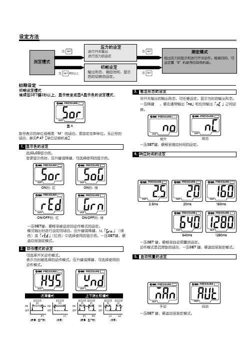
2. 动作模式的设定
可选择开关动作模式。 表示当时被选择的动作模式。压升键或降键,可选择使用的 动作模式。
PRESSURE
PRESSURE
PRESSURE
PRESSURE
PRESSURE
OUT
2.5ms
OUT
20ms
PRESSURE
PRESSURE
」与当时的设
OUT
常开
交替显示
PRESSURE
PRESSURE
OUT
第1位
OUT
常闭
一压SET键,便显示下一个设定值,一压升键△或降键 ,便 进入数值变更模式。(参见数值设定的方法)
自动预置时设定的场合 1. 自动预置的准备状态
测定模式时,一压SET键,便进入自动预置的准备状态,显示 「 」。此状态并没有进行压力设定装置的准备。在「 」 显示状态,同时压升键△和降键 ,可返回至测定模式。
PRESSURE
3. 输出形态的设定
对开关输出的输出形态,可任意设定。显示当时的输出形态。 一压降键 ,便在通常输出「 」和反向输出「 」之间切 换。
OUT
图A
型号表示的单位规格是“M”的场合,是固定在SI单位。无记号的 场合,参见P.47[单位切换机能]
1. 显示色的设定 选择LCD显示色。 变更显示色时,压升键或降键,可选择使用的显示色。
压力显示值
+ 0 施加压力
: 出厂时的显示值
: 显示值微调可能范围 注1)进行显示值微调时,压力设定值可以改变 –1 digit。
峰值保持·谷值保持机能 可以保持显示经常测定中的最大值和最小值。 峰值保持是压升键△1秒以上,则最大压力值闪动保持。解除 保持时,再压升键△1秒以上,就回复至被解除的测定模式。 谷值保持是压降键 1秒以上,则最小压力值闪动保持。解除保 持时,再压降键 1秒以上,就回复至被解除的测定模式。
- 1、下载文档前请自行甄别文档内容的完整性,平台不提供额外的编辑、内容补充、找答案等附加服务。
- 2、"仅部分预览"的文档,不可在线预览部分如存在完整性等问题,可反馈申请退款(可完整预览的文档不适用该条件!)。
- 3、如文档侵犯您的权益,请联系客服反馈,我们会尽快为您处理(人工客服工作时间:9:00-18:30)。
SMC电气比例阀中文手册
阀对流量的控制可以分为两种:
一种是开关控制:要么全开、要么全关,流量要么最大、要么最小,没有中间状态,如普通的电磁直通阀、电磁换向阀、电液换向阀。
另一种是连续控制:阀口可以根据需要打开任意一个开度,由此控制通过流量的大小,这类阀有手动控制的,如节流阀,也有电控的,如比例阀、伺服阀。
所以使用比例阀或伺服阀的目的就是:以电控方式实现对流量的节流控制(当然经过结构上的改动也可实现压力控制等),既然是节流控制,就必然有能量损失,伺服阀和其它阀不同的是,它的能量损失更大一些,因为它需要一定的流量来维持前置级控制油路的工作。