SMC电气比例阀中文手册
SMC ITV系列电动比例阀说明书加说明

E/P REGULATORMODEL NAMEITV1000, ITV2000, ITV3000 series ITV1000, ITV2000, ITV3000 seriesSeriesContentsP1 Safety instructions P2 Handling precautions P3-4 Wiring method P5-6 Setting methodP7 Key locking functionP8 Setting of min. pressure, max. pressure and switch output P9 Mode of switch outputP10 Setting of preset pressure P11 Reset functionP11 Error indicating function P12 Detail setting mode P13 Gain settingP13-14 Sensitivity setting P14 Zero clear P15 Initialize P15-16 LED displayP16URL MANUALCONTENTS CONTENTSThese safety instructions are intended to prevent a hazardous situation and/or equipment damage. These instructions indicate the level of potential hazard by labels of “CAUTION ” “WARNING ”, or “DANGER ”. To ensure safety, be sure to observe ISO 4414, JIS B 8370 and other safety practices.■Explanation of label△! WARNING WARNING Operator error could result in serious injury or loss of life. △!CAUTION CAUTIONOperator error could result in injury or equipment damage.△!①comp The compatibility atibility of pneumatic equipment is the responsibility of the person who who designs designs designs the pneumatic system or decides its specifications. the pneumatic system or decides its specifications.the pneumatic system or decides its specifications. Since the products specified here are used in various operating conditions, their compatibility for the specific pneumatic system must be based on specifications or after analyses and/or tests to meet your specific requirements. The expected performance and safety assurance will be the responsibility of the person who has determined the compatibility of the system. This person should continuously review the suitability of all items specified, referring to the latest catalog information with a view to giving due consideration to any possibility of equipment failure when configuring a system.②Only trained personnel should operate pneumatically operated machinery andequipment.equipment.Compressed air can be dangerous if an operator is unfamiliar with it. Assembly, handling or repair of pneumatic systems should be performed by trained and experienced operators.③Do not service machinery / equipment or attempt to remove components until safety is confirmed.safety is confirmed.A. Inspection and maintenance of machinery / equipment should only be performed once safetyof personnel and equipment is confirmed.B. When equipment is to be removed. Stop supplied air, exhaust the residual pressure, verify the release of air, turn the power off and confirm safety before performing maintenance.C. Before machinery / equipment is restarted, ensure safety before applying power.④Contact Contact SMC if the product is to be used in any of the following conditions. SMC if the product is to be used in any of the following conditions. SMC if the product is to be used in any of the following conditions.A. Conditions and environments beyond the given specifications, or if product is usedoutdoors.B. Installation on equipment in conjunction with atomic energy, railway, air navigation, vehicles, medical equipment, food and beverages, recreation equipment, emergency stop circuits, clutch and brake circuit in press applications, or safety equipment.C. An application which has the possibility of having negative effects on people, property, or animals requiring special safety analysis.△!If power to this product is cut off due to a power failure, etc. when it is in a controlled state, residual pressure will be retained temporarily. Handle carefully when operating with output pressure released to the atmosphere, as air will continue to flow out.If supply pressure to this product is interrupted or shut off, while the power is still on, the internal solenoid valve will continue to operate and a humming noise may be generated. Since the life of the product may be shortened, shut off the power supply also when supply pressure is interrupted or shut off.The optional cable connector is a 4 wire type. When the monitor output (analogue output or switch output) is not being used, prevent it from touching the other wires as a malfunction could occur.This product is adjusted for each specification at the time of shipment from the factory. Avoid careless disassembly or removal of parts, as this can lead to malfunction.△!Take the following steps to avoid malfunction due to noise.1)Install a line filter etc. to the AC powerline to reduce / eliminate power supplynoise.2)Avoid malfunction due to noise byinstalling this product and its wiringaway from strong electric fields, such asthose of motors and power line, etc.3)Be sure to implement protective measuresagainst load surge for induction loads(solenoid valves, relays etc.).4)Turn off the power supply beforeinstalling or removing the connector.Please note that the right angled cable connector does not rotate and is limited to only one entry direction.△!① Proceed carefully, as incorrect wiring can cause damage. ② Use DC power supply with sufficient capacity and a low ripple. ③ Turn off the power supply to remove and insert the connector. ④ Never turn the right angled type connector as it is not designed to turn.Note) The wire color isfor when optional cable is used.Wiring Wiring diagram (diagram (diagram (Power supply and input signal)Power supply and input signal)Power supply and input signal)Current/Voltage type(ITV※0※※-0、ITV※0※※-1、ITV※0※※-2、ITV※0※※-3)Preset input type(ITV※0※※-4)1 Brown Power supply 2 White Input signal 3 Blue GND(COMMON) 4 Black Monitor outputWiring diagram Wiring diagram((Monitor output Monitor output))△!When the monitor output is not being used, prevent it from touching the other wires as this can cause a malfunction.△!① If the incorrect key is pressed or incorrect information is displayed during setting, power must be shut off and the procedure started again.② It is recommended that the settings are changed without supply pressure. The product operates immediately maximum and minimum pressures are set and the S-key is pressed.③ It is recommended that the minimum pressure is output when air is supplied to the inlet, even if the input signal has not been entered.④ Output pressure from this product and state of operation are changed by changing of each setting and function. Each setting and function should be operated by trained and experienced operator.Flow of the setting(Note 1): Please refer to each contents about operation methode.(Note 2): The function of the setting of preset pressure is preset input typeonly.(Note 3): The function of the setting of switch output is switch output typeonly.设置预设压力设置最小压力设置最大压力设置选择输出详细设置增益灵敏度△!The keys are locked after turning the power on and can not be operated. Unlocking the keys(DEFAULT VALUE: 0%)(Note 2): The pressure of less than 0% is not output, even if F_1 is adjustedto less than 0%. (Note 3): F_2 is adjustable in a range from 10 to 120% of the rated value.(DEFAULT VALUE: 100%) (Note 4): Do not input the signal as like output the pressure of more than 100%.Please use in a range of rating. (Note 5): The difference between F_1 and F_2 is adjustable in a range of 10% ofthe rated value.(Note 6): The adjustment like making the relation of F_1>F_2 is not available.设置最小气压、最大气压以及选择输出F 1调整范围在-20%~90%之间如果F 1设置低于0%则无输出F 2调整范围在10%~120%之间不要将输入信号设置像输出信号超过100%,请设置在合理范围F 1和F 2不同在于设定值10%的范围The following operation types are available by setting P_1 and P_2.Note). This function is available for monitor output: switch output type (ITV※0※※-※2 and ITV※0※※-※3). ■ P_1<P_2 : ■P_1≧P_2 : Window comparator modeHysteresis mode■ P_1=P_2=0 : Out of range mode(The switch output turns on when set pressure is achieved.)输出模式的选择(DEFAULT VALUE: 0%)Reset method Reset content Item Reset content Application model F_1 0%F.S. Current・Voltage input type F_2 100%F.S. Current・Voltage input type P_1、P_2 100%F.S. Switch output type P_1~P_4 0%F.S. Preset input type (Note): Gain (GL) and sensitivity (SL) are not reset.Reset function Reset functionNormal operation does not require the adjustment of gain. This product can change the response with this gain setting.When the gain is changed to more larger, the response become quickly, but there is a possibility that stability is lost. Gain setting Gain settingRelation between setting of gain and response timeNormal operation does not require the adjustment of sensitivity.When the sensitivity is changed, the correction operation of pressure changes. When the sensitivity is changed to sharp, the hunting of pressure might be occurred. And, when the sensitivity is changed to dull, there is a possibility that staggering of gradual pressure occur, because the pressure correction become lower.Sensitivity setting Sensitivity settingThe display can be set to zero again by executing "zero clear".When "zero clear" is executed with residual pressure in the secondary piping, the pressure is assumed to be zero. Please execute the operation of "zero clear" with the supply pressure is intercepted, and the piping of the second side removed. is not executed."Initialize" is a function to return all the settings that the internal control constant are included to an initial value. Please execute "initialize" only when the error is displayed and this product doesn't operate at all. Please execute the "reset" function, when you want to return the pressure setting and the switch setting to an initial value.No Key operation LED Display① Unlock keys (refer to P8)② Press S-key for 2 seconds or more, then go to detail setting mode.Initialize InitializeThe range of the LED pressure display is different according to the pressure range and the unit of the display.unit ITV※01※ ITV※03※ ITV※05※ ITV209※ MPa 。020~.120 。100~.600 。180~.A80 - Kgf/cm 2 0。20~.120 1。00~6.00 1。80~A.80 - bar 0。20~.120 1。00~6.00 1。80~A.80 - PSI 3。0~18.0 14。0~84.0 -26~156 - kPa -20~120 -100~600 -180~A80 16~-96(note1):The mark "。" is blinking the decimal point, and it is shown a minus. (note2):When the digit overflows, the following of "9" are substituted by "A".(example: The following of 999(kPa) are displayed as A00(kPa), and it shows 1000 kPa.)(note3):When the display exceeds the lower bound value, "" is displayed. (note4):When the display exceeds the upper bound value, "" is displayed.This operation manual refers to all standard types and is partially applicable to special models.This operation manual is subject to change without prior notice or any obligation on the part of the manufacturer.LED LED display display。
SMC比例阀参数说明

产品名称:SMC比例阀参数说明
一种是开关控制:要么全开、要么全关,流量要么最大、要么最小,没有中间状态,如普通的电磁直通阀、电磁换向阀、电液换向阀。
另一种是连续控制:阀口可以根据需要打开任意一个开度,由此控制通过流量的大小,这类阀有手动控制的,如节流阀,也有电控的,如比例阀、伺服阀。
所以使用比例阀或伺服阀的目的就是:以电控方式实现对流量的节流控制(当然经过结构上的改动也可实现压力控制等),既然是节流控制,就必然有能量损失,伺服阀和其它阀不同的是,它的能量损失更大一些,因为它需要一定的流量来维持前置级控制油路的工作。
SMC VQZ-TF2Z496EN 三口气动阀说明书

VQZ100
VQZ200/300
Push type, Locking type (Tool required)
Contact SMC
Free
150 / 30
IP40 equivalent (DIN terminal: IP65 Note 5)) Refer to catalogue
Table 1.
Note 1) In case of the high pressure type, upper limit of max. operating pressure and external pilot pressure range is 1 MPa.
100V
Apparent
voltage [VA] AC
Note 1)
110V [115V] 200V 220V
[230V]
Surge voltage suppressor
Indicator Light
0.78 (With light: 0.81) 0.78 (With light: 0.87) 0.86 (With light: 0.89) 0.86 (With light: 0.87) [0.94 (With light: 0.97)] [0.94 (With light: 1.07)] 1.18 (With light:1.22) 1.15 (With light: 1.30) 1.3 (With light: 1.34) 1.27 (With light: 1.46) [1.42 (With light: 1.46)] [1.39 (With light: 1.60)]
SMC系列产品使用说明书
5.3对于1-PC和牙嵌式驱动空心轴的电动装置其安装方法是:起吊电动装置使1-PC空心轴孔与阀杆和键配合装入,牙嵌驱式空心轴上的牙嵌与阀门上阀杆螺母的牙嵌对准。用螺栓将电动装置与阀门紧固可靠。
4.1专用电动机:适合阀门的载荷特性和使用工况,型号YLT。
4.2减速机构:用于传递和增大电动机的动力。每个机座产品均有3~5种速比的蜗轮副和若干电机齿轮与蜗杆轴齿轮传动比的齿轮副,因而可获得较大的输出转速范围。
4.3驱动空心轴:它是电动装置的动力输出部件,有2-PC、1-PC、牙嵌式三种型式,结构可见(图10)~(图12)
2.基本技术参数
产品符合JB/T8528-1997《普通型阀门电动装置技术条件》
2.1动力电源:380V、50Hz三相正弦交流电(根据用户要求,某些规格可提供使用单相220V电源的电动机)。
2.2外壳防护等级:SMC-04、03 IP67
SMC-00~5 IP65
2.3使用环境温度:-20℃~40℃;-20℃~60℃(根据用户订货要求)
G·L·SW各列转体上触点的相对位置可任意布置,即同一列上的触点可以全部为“OFF”型式或为“OFF”“ON”两种型式。(最常用的是“OFF”“ON”的布置型式)。
G·L·SW中间的两列转体触点开关可做为阀门某两个中间位置的信号输出,也可将其调整到与两边的转体同步动作。
(图17)为典型控制原理时触点开关的布置型式。
电气接线程序及注意事项:
7.1确认电源电压与电动机使用电压相同。
SMC比例阀中文说明书

ITV1000-※1 ITV2000-※1 ITV3000-※1(模拟输出/电压型)使用说明书值此,谨对您选购SMC 公司的产品表示诚挚的谢意。
请仔细阅读本使用说明书,相信必将有助于您正确使用本产品。
为以防万一,请您一定好好保管此说明书。
安全注意事项这里所描述到的,是提请您正确安全的使用本产品,以防止对您自身和他人造成危害和损害的各种注意事项。
请结合ISO 4414, JIS B 8370以及其他的相关安全规则,务必遵守。
注意关于配管1.请将配管用空气吹净或清洗干净,以除去配管内的切屑,切削油及杂质等。
2.将配管和管接头拧紧时,请注意勿将配管的螺纹切屑及密封材混入配管中。
另需强调,使用密封胶带包卷管接头螺纹时,请在螺纹先端留出1.5~2个螺距的空间。
注意关于压缩气源1. 在靠近本产品的供气侧,请选择安装过滤精度在5μm 以下的空气过滤器。
2. 压缩空气若含有大量的水分,将导致本产品及其他的气动元件作动不良。
请实施相应对策,诸如设置后冷却器,空气干燥器,水分分离器等。
3. 在本产品内部大量附着由空气压缩机所产生的碳粉时,将导致其作动不良。
! !各部分名称外形尺寸配线电缆接线端子安装托架外形尺寸安装孔安装孔UP 键(△键) 设定键(SET 键) DOWN 键(▽键)显示用LEDSUP 接口OUT 接口压力表用接口安装托架(选配)右弯出线型电缆接线端子 (4芯)(选配)安装托架(选配)右弯出线型电缆接线端子直线出线型电缆接线端子 (4芯)(4芯)安装孔安装孔注1) 输出压力0.1MPa规格最大供给压力为0.2MPa。
注2) 超出规格范围时,会发生破损,请注意。
■ 配线方法电缆与本体的端子连接时,请以下记的形式进行配线。
注意因可能发生由于误配线而导致破损的情况,请使用时注意。
请使用容量足够大,脉动小的直流电源。
1 茶 供给电源2 白 输入信号3 青 GND (COMMON)4 黑显示输出注)电缆也有右弯出线型的。
SMC ZISE80中文设定说明
ISE:Mpa,ZSE:Kpa P(可选):psi 迟滞模式,常开 迟滞模式,常开
2.5 ms 模拟
1/1000 0% 手动
OFF OFF
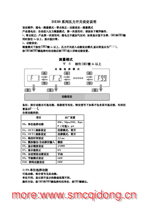
1) F0-单位选择功能
可选功能,部分型号无此功能。 单位不同,显示屏开显示的数值范围不同。 操作方法:按 和 键选择对应单位,按
键确认。
mmoorree::nn
设定值
模拟输出
按 键确认
自动移位输入
选择模拟输出将返回功能选择模 式
选择自动移位功能将进一步设定其功 能
mmoorree::nn
自动移位功能设定 按 和 选择自动移位功能
交替显示
自动移位显示
设定值
自动移位 按 键确认
归零移位选项 按 和 选择
mmoorree::nn
按键
设定输出类型-迟滞型/比较型 按 和 选择对应模式
进入 OUT1 规格设定 交替显示
输出类别
设定值
迟滞型
按键
设定输出模式-常开模式/常闭模式 按 和 选择常开/常闭
比较型 进入输出模式设定
交替显示
输出模式
设定值
设定顺序:通电—测量模式—零点校正—功能设定—测量模式
产品通电后,自动进入压力测量模式,第一次使用时,请按如下顺序操作。
1、零点校正:产品第一次使用时,通电且不施加气压时,如果显示值不为零, 和 键
同时按住 1s 以上,显示值归零。
2、功能设定:
测量模式下按住 键 2s 以上,压力开关进入功能设定模式,显示屏显示为
果密码连续 3 次错误,屏幕显示“LoC”,按键锁定。
④ 密码修改方法:出厂时出示密码为“000”。
执行上述①②③步至密码输入正确,屏幕显示“UnL”时,
SMC ITV1000,2000,3000电气比例阀设定手册

ITV1000-※1 ITV2000-※1 ITV3000-※1(模拟输出/电压型)使用说明书值此,谨对您选购SMC 公司的产品表示诚挚的谢意。
请仔细阅读本使用说明书之后正确使用本产品。
为了今后使用方便,请您妥善保管此使用说明书。
安全注意事项这里所指的注意事项,是为了让您正确安全的使用本产品,防止对您自身和他人造成危害和损害的各种事项。
请在遵守以下安全注意事项的同时,也请务必遵守ISO 4414, JIS B 8370以及其他的相关安全规则。
注意关于配管1.请将配管用空气吹净或清洗干净,以除去配管内的切屑,切削油及杂质等。
2.连接配管和接头时,请注意勿将配管的屑末及密封材混入配管中。
使用密封胶带时,务必在螺纹先端留出1.5~2个螺距的空间。
注意关于压缩气源1. 在靠近本产品的供气侧,请选择安装过滤精度在5μm 以下的空气过滤器。
2. 压缩空气若含有大量的水分,将导致本产品及其他的气动元件作动不良。
请实施相应对策,诸如设置后冷却器,空气干燥器,水分分离器等。
3. 在本产品内部大量附着由空气压缩机所产生的碳粉时,将导致其作动不良。
! !各部分名称外形尺寸配线电缆接线端子设定键(SET 键) DOWN 键(▽键)显示用LEDSUP 接口OUT 接口压力表用接口UP 键(△键) 安装托架(选配)右弯出线型电缆接线端子(4芯)安装孔外形尺寸安装托架安装孔安装孔(选配)安装托架(选配)右弯出线型电缆接线端子直线出线型电缆接线端子安装孔■ 规格供给压力 注1) 设定压力+ 0.1MPa,但最大为1MPa0.005~0.1MPa (ITV101※-※1,ITV201※-※1,ITV301※-※1)0.005~0.5MPa (ITV103※-※1,ITV203※-※1,ITV303※-※1)设定压力0.005~0.9MPa (ITV105※-※1,ITV205※-※1,ITV305※-※1)约200L/min (ANR) {ITV1000}(供给压力:0.7MPa)约1500L/min (ANR) {ITV2000}(供给压力:0.7MPa)最大流量约5000L/min (ANR) {ITV3000}(供给压力:0.7MPa)24VDC±10% (ITV10※0-※1,ITV20※0-※1,ITV30※0-※1)电源电压 注2)12~15VDC (ITV10※1-※1,ITV20※1-※1,ITV30※1-※1)电源电压 DC24V型:0.12A以下消费电流电源电压 DC12~15V型:0.18A以下4~20mADC (ITV10※※-01,ITV20※※-01,ITV30※※-01)电流型0~20mADC (ITV10※※-11,ITV20※※-11,ITV30※※-11)0~5VDC (ITV10※※-21,ITV20※※-21,ITV30※※-21)输入信号 注2)电压型0~10VDC (ITV10※※-31,ITV20※※-31,ITV30※※-31)电流型 250Ω以下输入阻抗电压型 约6.5KΩ直线性 ±1.0% F.S.以下延滞性 0.5% F.S.以下重复精度 ±0.5% F.S.以下最小压力调整 :调整范围 额定值的0~50%最大压力调整 :调整范围 额定值的10~100%附加机能键锁定机能 :持续摁住UP键2秒以上,再摁住SET键,可实现对操作键的锁定。
SMC 5 Port 电子阀门操作指南说明书
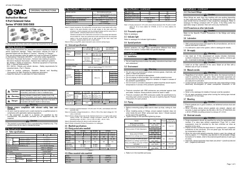
Instruction Manual 5 Port Solenoid ValveThe intended use of this valve is to control the movement of an actuator.These safety instructions are intended to prevent hazardous situationsand/or equipment damage. These instructions indicate the level ofpotential hazard with the labels of “Caution,” “Warning” or “Danger.”They are all important notes for safety and must be followed in additionto International Standards (ISO/IEC) *1), and other safety regulations.*1) ISO 4414: Pneumatic fluid power - General rules relating to systems.ISO 4413: Hydraulic fluid power - General rules relating to systems.IEC 60204-1: Safety of machinery - Electrical equipment of machines.(Part 1: General requirements)ISO 10218-1: Robots and robotic devices - Safety requirements forindustrial robots - Part 1: Robots.•Refer to product catalogue, Operation Manual and HandlingPrecautions for SMC Products for additional information.• Keep this manual in a safe place for future reference.Warning•Always ensure compliance with relevant safety laws andstandards.•All work must be carried out in a safe manner by a qualified person incompliance with applicable national regulations.•If this equipment is used in a manner not specified by themanufacturer, the protection provided by the equipment may beimpaired.Caution•The product is provided for use in manufacturing industries only. Thisproduct must not be used in residential areas.2 SpecificationsNote 1)Impact resistance: No malfunction occurred when it was tested with a droptester in the axial direction and at right angles to the main valve andarmature; in both energized and de-energised states and for every time ineach condition. (Values quoted are for a new valve)Vibration resistance: No malfunction occurred in a one-sweep test between45 and 2000 Hz. Tests are performed at both energized and de-energizedstates in the axial direction and at right angles to the main valve andarmature. (Values quoted are for a new valve).Note 2) When using IP65, select main/pilot valve common exhaust type.Note 1) Common solenoid between 110 VAC and 115 VAC, and between 220 VACand 230 VAC.Note 2) Allowable voltage fluctuation is –15% to +5% of the rated voltage for 115VAC or 230 VAC.Note 3) Since voltage drops due to the internal circuit in S, Z, T types (with powersaving circuit), the allowable voltage fluctuation should be within thefollowing range. 24 VDC: –7% to +10% 12 VDC: –4% to +10%.Note 4) Bracketed values (#) refers to with indicator light.Note 5) Refer to Specific Product Precautions 4 in catalogue.2.3 Manifold specificationsNote 1) Supply pressure to 1(P) ports and exhaust pressure from R ports on bothsides for 10 or more station for VF3000, or for 5 or more stations forVF5000.2.4 Pneumatic symbolRefer to catalogue.2.5 Indicator lightRefer to catalogue for indicator light location.2.6 Special productsWarningSpecial products (-X) might have specifications different from thoseshown in this section. Contact SMC for specific drawings.3 Installation3.1 InstallationWarning•Do not install the product unless the safety instructions have been readand understood.3.2 EnvironmentWarning•Do not use in an environment where corrosive gases, chemicals, saltwater or steam are present.•Do not use in an explosive atmosphere.•Do not expose to direct sunlight. Use a suitable protective cover.•Do not install in a location subject to vibration or impact in excess ofthe product’s specifications.•Do not mount in a location exposed to radiant heat that would result intemperatures in excess of the product’s specification s.•Products compliant with IP65 enclosures are protected against dustand water, however, these products cannot be used in water.•Products compliant with IP65 enclosures satisfy the specifications bymounting each product properly. Be sure to read the Specific ProductPrecautions for each product.3.3 PipingCaution•Before connecting piping make sure to clean up chips, cutting oil, dustetc.•When installing piping or fittings, ensure sealant material does notenter inside the port. When using seal tape, leave 1 thread exposedon the end of the pipe/fitting.•Tighten fittings to the specified tightening torque.•Refer to 2.3 for manifold port sizes.3.3.1 One-touch fittingsCautionWhen fittings are used, they may interfere with one another dependingon their types and sizes. Therefore, the dimensions of the fittings to beused should first be confirmed in their respective catalogues. Refer tocatalogue for fittings compliant with VF series. If the fitting within theapplicable range is selected, there will not be any interference.3.3.2 Precautions on other tube brandsCautionRefer to the Specific Product Precautions in the fittings and tubingcatalogue.3.4 LubricationCaution•SMC products have been lubricated for life at manufacture, and do notrequire lubrication in service.•If a lubricant is used in the system, refer to catalogue for details.3.5 Air supplyWarning•Use clean air. If the compressed air supply includes chemicals,synthetic materials (including organic solvents), salinity, corrosive gasetc., it can lead to damage or malfunction.Caution•Install an air filter upstream of the valve. Select an air filter with afiltration size of 5 μm or smaller.3.6 Manual overrideWarning•Regardless of an electric signal for the valve, the manual override isused for switching the main valve. Since connected equipment willoperate when the manual override is activated, confirm that conditionsare safe prior to activation.•Locked manual overrides might prevent the valve responding to beingelectrically de-energised or cause unexpected movement in theequipment.•Refer to the catalogue for details of manual override operation.•Do not apply excessive torque when turning the locking type manualoverride (0.1 N·m or less).3.7 MountingCaution•Ensure gaskets are in good condition, not deformed and are dust anddebris free.•When mounting valves ensure gaskets are present, aligned andsecurely in place and tighten the M4 (M4 x 39.5 for VF1000/3000, M4x 48 for VF5000) mounting screws to a torque of 1.4 N∙m.3.8 Electrical circuitsCaution•Surge suppression should be specified by using the appropriate partnumber. If a valve type without suppression (Type ‘Nil’) is used,suppression must be provided by the host controller as close aspossible to the valve.•Please connect correctly the lead wires to + (positive) and – (negative)indications on the connector. (For non-polar type, the lead wires canbe connected to either one.)•When the valve with polarity protection diode is used, the voltage willdrop by approx. 1 V. Therefore, pay attention to the allowable voltagefluctuation (For details, refer to the solenoid specifications of each typeof valve).•Solenoids, whose lead wires have been pre-wired: + (positive) side redand – (negative) side black.ORIGINAL INSTRUCTIONS3 Installation - continued3.8.1 DC - Polar typeFigure 1. With surge voltage suppressor (#S)Figure 3. DIN or Conduit terminal with light/surge voltage suppressor(Standard type #Z)3.8.2 DC - Non-polar typeFigure 4. With surge voltage suppressor (Standard #R/Low wattage type #R, #S)Figure 6. DIN or Conduit terminal with light/surge voltage suppressor(Standard #U/Low wattage type #Z)3.8.3 Power savingFigure 7. Power saving circuitNote) Effective energizing time is over 40 ms at 24 VDC. Refer to catalogue fordetails of the electrical power waveform.3 Installation - continued3.8.4 ACFigure 8. Grommet or L/M-type plug with light/surge voltage suppressor (#Z) 3.9 Electrical connectorsCaution3.9.1 DIN terminal• Refer to catalogue for how to use DIN connector.• Refer to catalogue for how to change DIN connector direction. • Applicable cable diameter O.D.: ø3.5 to ø7.3.9.2 DIN (EN175301-803) terminalY type DIN terminal corresponds to the DIN connector with terminal pitch 10 mm, which complies with EN175301-803B. Since the terminal pitch is different from the D type DIN connector, these two types are not interchangeable.Y Type D typeFigure 10. D/Y type DIN terminal diagramFigure 11. DIN connector assembly (Standard type)Figure 12. DIN connector assembly (Low wattage specification)3 Installation - continuedFigure 13. DIN connector pin wiring diagram3.9.3 Conduit terminal• Refer to catalogue for how to use Conduit terminal.• For polar type refer to terminal polarity shown in figure 14. • Applicable cable diameter O.D.: ø4.5 to ø7.Figure 14. Conduit terminal assembly3.9.4 L/M-Type plug connectorRefer to catalogue for how to order and how to use plug connector assemblyFigure 15. Connector attachment/detachment (standard type)Figure 16. Connector attachment/detachment (low wattage type)3 Installation - continuedFigure 17. Crimping lead wire and socket connectionStandard typeFigure 18. Socket with lead wire attachment/detachment3.10 Residual voltageCaution• If a diode or varistor voltage suppressor is used, the suppressor arrests the back EMF voltage from the coil to the level indicated in Table 6. • Ensure the transient voltage is within the specification of the host controller.• Valve response time is dependent on surge suppression method selected.Surge voltage suppressor DCAC 24 V12 VDiode Approx. 1 VApprox. 1 VVaristorApprox. 47 V Approx. 32 V-Table 6.3.11 Countermeasure for surge voltageCaution• At times of sudden interruption of the power supply, the energy stored in a large inductive device may cause non-polar type valves in a de-energised state to switch.• When installing a breaker circuit to isolate the power, consider a valve with polarity (with polarity protection diode), or install a surge absorption diode across the output of the breaker. 3.12 Extended period of continuous energizationWarning• If a valve is continuously energized for an extended period of time, the temperature of the valve will increase due to the heat generated by the coil assembly. This will likely adversely affect the performance of the valve and any nearby peripheral equipment. Therefore, if the valve is to be energized for periods of longer than 30 minutes at a time or if during the hours of operation the energized period per day is longer than the de-energized period, we advise using a valve with specifications listed below.• Pilot operated: A 0.4 W or lower valve, such as the SY series, or a valve with a power-saving circuit. 3.13 Effect of back pressure when using a manifoldWarning• Use caution when valves are used on a manifold, because an actuator may malfunction due to back-pressure.• Special caution must be taken when using 3 position exhaust centre valve or when driving a single acting cylinder. To prevent a malfunction, implement counter measures such as using a single EXH spacer assembly or an individual exhaust manifold.4 How to OrderRefer to catalogue for ‘How to Order’.5 Outline DimensionsRefer to catalogue for outline dimensions.Polarity protection diodeRedRedPolarity protection diodeLEDCoilCoilDiodeDiodeBlackBlackPolarity protection diodeDiodeCoilFor DIN type, installed in the connectorLEDCoilVaristor VaristorCoilLEDFor DIN type, installed in the connectorPolarity protection diodeCoilLEDDiodeP W M c i r c u i tVaristor CoilVaristorCoilLEDNeon light(LED for 24 VAC)For DIN type, installed in the connector Figure 2. Grommet or L/M-type plug with light/surge voltage suppressor (#Z) Figure 5. Grommet or L/M-type plug with light/surge voltage suppressor (#U)CoilVaristorLEDFigure 9. DIN or Conduit terminal with light/surge voltage suppressor (#Z)Ground nutTightening torque 2.5 to 3.75 N∙mWasherGrommetVoltage symbolLocation for mounting lightPolarity indicationTerminal screw 3 locations Tightening torque 0.4 to 0.5 N∙mTerminal blockHousingSet screwTightening torque 0.5 to 0.6 N∙m + - 1 21 2GroundLEDLEDNLRRR DD: Protective diode R: Resistor NL: Neon light Washer Set screwTightening torque 0.5 to 0.6 N∙m Terminal block coverGrommet (Rubber)Ground nut Tightening torque 2.5 to 3.75 N∙mGround terminal screw Tightening torque 0.5 to 0.6 N∙mTerminal screw 2 locationsTightening torque 0.5 to 0.6 N∙m(+) (-)GroundGroundGrommetWasherRating symbolGland nutTightening torque1.65 to2.5 N∙mHolding screw Tightening torque 0.4 N∙mHousing Terminal block Location for mounting light NotchFigure of notchTerminal screw 3 locations Tightening torque 0.2 to 0.25 N∙mPinLead wire SocketConnectorLeverGroove CoverCoverGroovePinDC polarity indicationLever Core wire crimping area Crimping areaHookCore wireLead wire0.2 to 0.33 mm 2Max. cover diameter: ø1.9 mm (standard type) Max. cover diameter: ø1.7 mm (low wattage type) Socket(DXT170-71-1)CoveringCover GrooveConnectorDC polarity indication SocketPart no. DXT170-71-1Lead wireHookLeverCover GroovePinPinSocketLead wireConnector Hook Insert a socket into square hole Not in useConnectorHookLead wire SocketLow wattageAC (#Z / Low wattage type) DC (#Z)DC (#U / Low wattage type)6.1General maintenanceCaution• Not following proper maintenance procedures could cause the product to malfunction and lead to equipment damage.• If handled improperly, compressed air can be dangerous.•Maintenance of pneumatic systems should be performed only by qualified personnel.• Before performing maintenance, turn off the power supply and be sure to cut off the supply pressure. Confirm that the air is released to atmosphere.• After installation and maintenance, apply operating pressure and power to the equipment and perform appropriate functional and leakage tests to make sure the equipment is installed correctly.• If any electrical connections are disturbed during maintenance, ensure they are reconnected correctly and safety checks are carried out as required to ensure continued compliance with applicable national regulations.• Do not make any modification to the product.• Do not disassemble the product, unless required by installation or maintenance instructions. 6.2 MountingCautionRefer to 3.7 Mounting for how to mount valve to sub-plate or manifold. 6.3 Maintainable partsCaution• Refer to catalogue for how to order pilot for how to order and replace pilot valves (Not available for Low wattage specification valves). Recommended tightening torque for M2.5 pilot valve mounting screws: 0.32 N∙m.• Refer to catalogue for how to order gaskets, mounting screws, manifold accessories, electrical connector assemblies and sub-plates.7.1 Limited warranty and disclaimer/compliance requirementsCautionRefer to Handling Precautions for SMC Products.WarningNote) Applies to when the spool is at the end position and at an intermediateposition .7.3 Cannot be used as an emergency shut-off valveThis product is not designed for safety applications such as an emergency shut-off valve. If the valves are used in this type of system, other reliable safety assurance measures should be adopted. 7.4 Intermediate stoppingRefer to Handling Precautions for 3/4/5 port Solenoid Valves.7.5 Holding of pressureSince valves are subject to air leakage, they cannot be used for applications such as holding pressure (including vacuum) in a system.Caution7.6 Leakage voltageEnsure that any leakage voltage caused by the leakage current when the switching element is OFF causes ≤ 3% (for DC coils) or ≤ 8% (for AC coils) of the rated voltage across the valve.7.7 Low temperature operationUnless otherwise indicated in the specifications for each valve, operation is possible to -10˚C, but appropriate measures sh ould be taken to avoid solidification or freezing of drainage and moisture, etc.7.8 Momentary energizationIf a double solenoid valve is operated with momentary energization, it should be energized for at least 0.1 second. However, depending on the secondary load conditions, it should be energized until the cylinder reaches the stroke end position, as there is a possibility of malfunction otherwise.7.9 Class and group description• This product is group 1, class A equipment according to EN55011. • Group 1 equipment does not intentionally generate radio-frequency energy in the range 9kHz to 400 GHz.• Class A equipment is equipment suitable for use in all locations other than those allocated in residential environments and those directly connected to a low voltage power supply network which supplies buildings used for domestic purposes.• This equipment is not intended for use in residential environments and may not provide adequate protection to radio reception in such environments.7.10 Cable length to connectThe cable to connect the product shall be less than or equal to 30m. 7.11 Connecting the power supplyThis product is not intended to be directly connected to any DC Distribution network.This product shall not be disposed of as municipal waste. Check your local regulations and guidelines to dispose this product correctly, in order to reduce the impact on human health and the environment.9 ContactsRefer to or www.smc.eu for your local distributor/importer.URL : https:// (Global) https:// www.smc.eu (Europe) SMC Corporation, 4-14-1, Sotokanda, Chiyoda-ku, Tokyo 101-0021, JapanSpecifications are subject to change without prior notice from the manufacturer. © 2022 SMC Corporation All Rights Reserved. Template DKP50047-F-085M。
- 1、下载文档前请自行甄别文档内容的完整性,平台不提供额外的编辑、内容补充、找答案等附加服务。
- 2、"仅部分预览"的文档,不可在线预览部分如存在完整性等问题,可反馈申请退款(可完整预览的文档不适用该条件!)。
- 3、如文档侵犯您的权益,请联系客服反馈,我们会尽快为您处理(人工客服工作时间:9:00-18:30)。
S M C电气比例阀中文手册 Prepared on 24 November 2020
SMC电气比例阀中文手册
阀对流量的控制可以分为两种:
一种是开关控制:要么全开、要么全关,流量要么最大、要么最小,没有中间状态,如普通的电磁直通阀、电磁换向阀、电液换向阀。
另一种是连续控制:阀口可以根据需要打开任意一个开度,由此控制通过流量的大小,这类阀有手动控制的,如节流阀,也有电控的,如比例阀、伺服阀。
所以使用比例阀或伺服阀的目的就是:以电控方式实现对流量的节流控制(当然经过结构上的改动也可实现压力控制等),既然是节流控制,就必然有能量损失,伺服阀和其它阀不同的是,它的能量损失更大一些,因为它需要一定的流量来维持前置级控制油路的工作。