力士乐vt3000比例阀放大板说明书
SMC ITV系列电动比例阀说明书加说明

E/P REGULATORMODEL NAMEITV1000, ITV2000, ITV3000 series ITV1000, ITV2000, ITV3000 seriesSeriesContentsP1 Safety instructions P2 Handling precautions P3-4 Wiring method P5-6 Setting methodP7 Key locking functionP8 Setting of min. pressure, max. pressure and switch output P9 Mode of switch outputP10 Setting of preset pressure P11 Reset functionP11 Error indicating function P12 Detail setting mode P13 Gain settingP13-14 Sensitivity setting P14 Zero clear P15 Initialize P15-16 LED displayP16URL MANUALCONTENTS CONTENTSThese safety instructions are intended to prevent a hazardous situation and/or equipment damage. These instructions indicate the level of potential hazard by labels of “CAUTION ” “WARNING ”, or “DANGER ”. To ensure safety, be sure to observe ISO 4414, JIS B 8370 and other safety practices.■Explanation of label△! WARNING WARNING Operator error could result in serious injury or loss of life. △!CAUTION CAUTIONOperator error could result in injury or equipment damage.△!①comp The compatibility atibility of pneumatic equipment is the responsibility of the person who who designs designs designs the pneumatic system or decides its specifications. the pneumatic system or decides its specifications.the pneumatic system or decides its specifications. Since the products specified here are used in various operating conditions, their compatibility for the specific pneumatic system must be based on specifications or after analyses and/or tests to meet your specific requirements. The expected performance and safety assurance will be the responsibility of the person who has determined the compatibility of the system. This person should continuously review the suitability of all items specified, referring to the latest catalog information with a view to giving due consideration to any possibility of equipment failure when configuring a system.②Only trained personnel should operate pneumatically operated machinery andequipment.equipment.Compressed air can be dangerous if an operator is unfamiliar with it. Assembly, handling or repair of pneumatic systems should be performed by trained and experienced operators.③Do not service machinery / equipment or attempt to remove components until safety is confirmed.safety is confirmed.A. Inspection and maintenance of machinery / equipment should only be performed once safetyof personnel and equipment is confirmed.B. When equipment is to be removed. Stop supplied air, exhaust the residual pressure, verify the release of air, turn the power off and confirm safety before performing maintenance.C. Before machinery / equipment is restarted, ensure safety before applying power.④Contact Contact SMC if the product is to be used in any of the following conditions. SMC if the product is to be used in any of the following conditions. SMC if the product is to be used in any of the following conditions.A. Conditions and environments beyond the given specifications, or if product is usedoutdoors.B. Installation on equipment in conjunction with atomic energy, railway, air navigation, vehicles, medical equipment, food and beverages, recreation equipment, emergency stop circuits, clutch and brake circuit in press applications, or safety equipment.C. An application which has the possibility of having negative effects on people, property, or animals requiring special safety analysis.△!If power to this product is cut off due to a power failure, etc. when it is in a controlled state, residual pressure will be retained temporarily. Handle carefully when operating with output pressure released to the atmosphere, as air will continue to flow out.If supply pressure to this product is interrupted or shut off, while the power is still on, the internal solenoid valve will continue to operate and a humming noise may be generated. Since the life of the product may be shortened, shut off the power supply also when supply pressure is interrupted or shut off.The optional cable connector is a 4 wire type. When the monitor output (analogue output or switch output) is not being used, prevent it from touching the other wires as a malfunction could occur.This product is adjusted for each specification at the time of shipment from the factory. Avoid careless disassembly or removal of parts, as this can lead to malfunction.△!Take the following steps to avoid malfunction due to noise.1)Install a line filter etc. to the AC powerline to reduce / eliminate power supplynoise.2)Avoid malfunction due to noise byinstalling this product and its wiringaway from strong electric fields, such asthose of motors and power line, etc.3)Be sure to implement protective measuresagainst load surge for induction loads(solenoid valves, relays etc.).4)Turn off the power supply beforeinstalling or removing the connector.Please note that the right angled cable connector does not rotate and is limited to only one entry direction.△!① Proceed carefully, as incorrect wiring can cause damage. ② Use DC power supply with sufficient capacity and a low ripple. ③ Turn off the power supply to remove and insert the connector. ④ Never turn the right angled type connector as it is not designed to turn.Note) The wire color isfor when optional cable is used.Wiring Wiring diagram (diagram (diagram (Power supply and input signal)Power supply and input signal)Power supply and input signal)Current/Voltage type(ITV※0※※-0、ITV※0※※-1、ITV※0※※-2、ITV※0※※-3)Preset input type(ITV※0※※-4)1 Brown Power supply 2 White Input signal 3 Blue GND(COMMON) 4 Black Monitor outputWiring diagram Wiring diagram((Monitor output Monitor output))△!When the monitor output is not being used, prevent it from touching the other wires as this can cause a malfunction.△!① If the incorrect key is pressed or incorrect information is displayed during setting, power must be shut off and the procedure started again.② It is recommended that the settings are changed without supply pressure. The product operates immediately maximum and minimum pressures are set and the S-key is pressed.③ It is recommended that the minimum pressure is output when air is supplied to the inlet, even if the input signal has not been entered.④ Output pressure from this product and state of operation are changed by changing of each setting and function. Each setting and function should be operated by trained and experienced operator.Flow of the setting(Note 1): Please refer to each contents about operation methode.(Note 2): The function of the setting of preset pressure is preset input typeonly.(Note 3): The function of the setting of switch output is switch output typeonly.设置预设压力设置最小压力设置最大压力设置选择输出详细设置增益灵敏度△!The keys are locked after turning the power on and can not be operated. Unlocking the keys(DEFAULT VALUE: 0%)(Note 2): The pressure of less than 0% is not output, even if F_1 is adjustedto less than 0%. (Note 3): F_2 is adjustable in a range from 10 to 120% of the rated value.(DEFAULT VALUE: 100%) (Note 4): Do not input the signal as like output the pressure of more than 100%.Please use in a range of rating. (Note 5): The difference between F_1 and F_2 is adjustable in a range of 10% ofthe rated value.(Note 6): The adjustment like making the relation of F_1>F_2 is not available.设置最小气压、最大气压以及选择输出F 1调整范围在-20%~90%之间如果F 1设置低于0%则无输出F 2调整范围在10%~120%之间不要将输入信号设置像输出信号超过100%,请设置在合理范围F 1和F 2不同在于设定值10%的范围The following operation types are available by setting P_1 and P_2.Note). This function is available for monitor output: switch output type (ITV※0※※-※2 and ITV※0※※-※3). ■ P_1<P_2 : ■P_1≧P_2 : Window comparator modeHysteresis mode■ P_1=P_2=0 : Out of range mode(The switch output turns on when set pressure is achieved.)输出模式的选择(DEFAULT VALUE: 0%)Reset method Reset content Item Reset content Application model F_1 0%F.S. Current・Voltage input type F_2 100%F.S. Current・Voltage input type P_1、P_2 100%F.S. Switch output type P_1~P_4 0%F.S. Preset input type (Note): Gain (GL) and sensitivity (SL) are not reset.Reset function Reset functionNormal operation does not require the adjustment of gain. This product can change the response with this gain setting.When the gain is changed to more larger, the response become quickly, but there is a possibility that stability is lost. Gain setting Gain settingRelation between setting of gain and response timeNormal operation does not require the adjustment of sensitivity.When the sensitivity is changed, the correction operation of pressure changes. When the sensitivity is changed to sharp, the hunting of pressure might be occurred. And, when the sensitivity is changed to dull, there is a possibility that staggering of gradual pressure occur, because the pressure correction become lower.Sensitivity setting Sensitivity settingThe display can be set to zero again by executing "zero clear".When "zero clear" is executed with residual pressure in the secondary piping, the pressure is assumed to be zero. Please execute the operation of "zero clear" with the supply pressure is intercepted, and the piping of the second side removed. is not executed."Initialize" is a function to return all the settings that the internal control constant are included to an initial value. Please execute "initialize" only when the error is displayed and this product doesn't operate at all. Please execute the "reset" function, when you want to return the pressure setting and the switch setting to an initial value.No Key operation LED Display① Unlock keys (refer to P8)② Press S-key for 2 seconds or more, then go to detail setting mode.Initialize InitializeThe range of the LED pressure display is different according to the pressure range and the unit of the display.unit ITV※01※ ITV※03※ ITV※05※ ITV209※ MPa 。020~.120 。100~.600 。180~.A80 - Kgf/cm 2 0。20~.120 1。00~6.00 1。80~A.80 - bar 0。20~.120 1。00~6.00 1。80~A.80 - PSI 3。0~18.0 14。0~84.0 -26~156 - kPa -20~120 -100~600 -180~A80 16~-96(note1):The mark "。" is blinking the decimal point, and it is shown a minus. (note2):When the digit overflows, the following of "9" are substituted by "A".(example: The following of 999(kPa) are displayed as A00(kPa), and it shows 1000 kPa.)(note3):When the display exceeds the lower bound value, "" is displayed. (note4):When the display exceeds the upper bound value, "" is displayed.This operation manual refers to all standard types and is partially applicable to special models.This operation manual is subject to change without prior notice or any obligation on the part of the manufacturer.LED LED display display。
力士乐阀分类说明书

序号名称型号交货期备注1 换向阀 4WE6(D、Y)62/EG24N9K4 现货原装REXROTH力士乐2 换向阀 4WE6 (J、E) 62/EG24N9K4 现货原装REXROTH力士乐3 换向阀 4WE10 (D Y) D33/CG24N9K4 现货原装REXROTH力士乐4 换向阀 4WE10 (J E) D33/CG24N9K4 现货原装REXROTH力士乐5 换向阀 4WE6(D、Y)62/HG24N9K4 现货原装REXROTH力士乐6 换向阀 4WE6 (J、E) 62/HG24N9K4 现货原装REXROTH 力士乐7 换向阀 4WEH16E7X/6EG24 现货原装REXROTH力士乐8 换向阀 4WEH16J7X/6EG24 现货原装REXROTH力士乐9 换向阀 4WEH16D7X/6EG24 现货原装REXROTH力士乐10 换向阀 4WEH16Y7X/6EG24 现货原装REXROTH力士乐11 压力阀 ZDR6DP2-4X/75YM 现货原装REXROTH力士乐12 压力阀 ZDR6DP2-4X/150YM 现货原装REXROTH力士乐13 压力阀 ZDR6DP2-4X/210YM 现货原装REXROTH力士乐14 压力阀 ZDR10DP2-5X/150YM 现货原装REXROTH力士乐15 单向阀 Z2FS10-5-3X/ 现货原装REXROTH力士乐16 单向阀 Z2FS6-2-4X/2QV 现货原装REXROTH力士乐17 单向阀 Z2S10-1-3X 现货原装REXROTH力士乐18 单向阀 Z2S6-1-6X 现货原装REXROTH公司主营博世力士乐全系列产品,型号齐全,价格低。
联系人:赵腾飞我公司郑重承诺:凡我公司所售力士乐产品,质量保证一年,如果有质量问题,无条件更换!力士乐产品详细:溢流阀:DBD,ZDB,Z2DB,DB-4X/W65,DB-5X减压阀:DR6DP,DR10DP,ZDR,DR-4X,DR10K电磁阀:4WE6, 4WE10,M-3SE单向阀:Z1S, Z2S,M-SR柱塞泵系列:A4V、A10VS0、A2FO A4VSO,A7VO,A7VSO液压马达 A2FE、A2FM压力继电器HED系列力士乐DBD,ZDB,Z2DB,DB-4X/W65,DB-5X全部系列产品特价销售!!!1.比例伺阀:01 03 03 04 05 06 07 08 09 09 00 01 04 05 06 03 00 00 01 05 00 01 03 022. 电液比例控制阀:01 00 04 06 07 08 09 03 00 09 01 02 04 05 07 04 06 02 03 02 01 07 07 093. 齿轮泵:06 09 05 00 09 03 05 02 004. 放大器:00 01 03 04 06 01 06 08 04 06 00 06 07 00 3 04 05 07 00 075. 方向控制阀:05 01 03 00 01 03 07 02 07 06 08 07 056轴向柱塞泵:A10VSO10DR/52R-PPA14N00 A10VO18DFR1/31R-PPA12N00 A10VSO28DFR1/31R-PPA12N00 A10VSO45DFR1/31R-PPA12N00 A10VSO71DFR1/31R-PPA12N00 A10VSO100DFR1/31R-PPB12N00 A10VSO140DFR1/31R-PPA12N00 A10VSO45DFR1/32R-PPB12N00 A10VSO100DFR1/32R-PPB12N00A10VSO071DFR1/32R-VPB12N00A10VSO140DFR1/32R-VPB12N00A10VSO140DRS/32R-VPB22U99 A10VSO140DR/31R-PPB12N007.电磁阀:4WE6C6X/EG24N9K4,4WE6D6X/EG24N9K4,4WE6Y6X/EG24N9K4,4WE6E6X/EG24N9K4,4WE6J6X/EG24N9K4,4WE6H6X/EG24N9K4,4WE6M6X/EG24N9K4,4WE6G6X/EG24N9K4,4WE10D3X/CG24N9K4,4WE10E3X/CG24N9K4,4WE10J3X/CG24N9K4,4WE10G3X/CG24N9K4,4WE6Y7X/HG24N9K4,4WE6D7X/HG24N9K4,4WE6E7X/HG24N9K4,4WE6J7X/HG24N9K4,4WE6Y7X/HG24N9K4,4WE6H7X/HG24N9K4,4WE6G7X/HG24N9K4;8.溢流阀:DBW10B1-5X/200-6EG24N9K4,DBW20B1-5X/200-6EG24N9K4,DBW10B1-5X/315-6EG24N9K4,DBW20B2-5X/315-6EG24N9K4。
Rexroth放大器VT系列样本资料下载
Rexroth放大器VT系列样本资料下载用于比例方向阀和比例压力阀的阀放大器型号 VT-VSPA2-1组件系列 2X模拟,欧洲板卡格式适用于操纵比例方向阀:– 4WRA 6...-2X,4WRA 10 (2X)– 4WRZ (7X)和比例压力阀:– 3DREP 6..2X特点差分输入(±10 V)4 个可挪用操纵值输入(±10 V)电流输入(4 … 20 mA)通过 24 V 输入或跳线改变内部操纵值信号极性通过相位识别(24 V 输入)或斜坡时刻挪用(24 V 输入)选择斜坡时刻(选件 T5)通过跳线选择斜坡时刻范围通过可别离调剂的阶跃电平和最大值进行特性曲线校正选通输入"斜坡开/关"输入"预备就绪"输出信号可通断的测量插口(选项 T5)电源反向极性爱惜电源带直流/直流转换器,不改变零电位注意事项:利用 VT-VSPA2-1-2X 放大器板卡作为 VT 3000-3X,VT 3006-3X,VT 3013-3X,VT 3014-3X,VT 3017-3X,VT 3018-3X,VT 3026-3X,VT-VSPA2-1-1X/…或VT-VSPA2-50-1X/…的替代品时,确保遵守符合30110-Z 附加信息的配置和设置信息。
附件开放式板卡插槽 VT 3002-1-2X/48F功能开放式板卡插槽 VT 3002-1-2X/48F(请参阅样本 29928)附件供电设备 [1]放大器板卡随附了带接通电流限制器的供电设备。
此设备提供了所有内部所需的正和负电源电压。
操纵值规格通过差分输入 [2] 和电流输入 [3],启用信号 [4] 及零位偏移[5](调零电位计 "Zw")中可用的外部操纵值信号之和(总和 [6]),计算内部操纵值信号。
电流和电压输入之间不进行切换。
输入始终可用(请参阅电路图)。
操纵值启用 [4]能够选择四个操纵值信号 "w1" 至 "w4"。
力士乐驱动器使用说明
力士乐驱动器参数调试说明本说明书针对非正弦用力士乐驱动器。
主要讲述驱动软件的使用、参数配置、PID调节等。
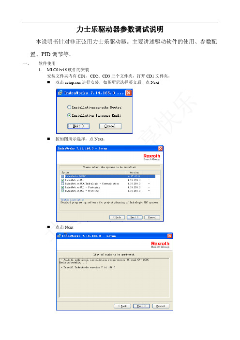
一、软件使用1.MLC04v16软件的安装安装文件夹内有CD1、CD2、CD3三个文件夹,打开CD1文件夹,⏹双击setup.exe进行安装,如图所示选择英文后,点Next⏹按如图所示选择,点Next。
⏹点击Next⏹点击Next⏹选择接受,后点击Next⏹输入名称,点击Next⏹选择安装目录,然后点击Next⏹点Install⏹安装进度如下:真个过程可能要10多分钟,看电脑性能。
⏹完成窗口如下:⏹完成后需要重启。
点”是”自动重启,点”否”则不重启。
2.软件操作⏹打开软件●双击桌面快捷方式,如下图所示。
●通过点击开始菜单->程序->Rexroth->IndraWorks7.14.166.0->Engineering.来打开。
⏹软件使用●工程的使用如下图点击Create an empty project为建立一个新工程。
点击Open project打开一个现有工程。
点击Scan for devices扫描串口总线上的设备点击Restore project把保存的已压缩工程,解压缩。
点击下面快捷按钮,第一个为新建工程,第二个位打开现有工程。
点击File下拉菜单后,New:新建工程;Open:打开工程。
与伺服启动器联机打开工程后变为点黄色图标进入虚拟模式。
点蓝色图标连接实际驱动器。
如果端口配置正常则直接联机,否则会弹出如下窗口。
点击Scan for Device后弹出如下窗口点Next后自动寻找设备。
未找到设备则弹出下面创库示波器功能点Diagnostics下拉菜单,点击Oscilloscope下图所示为示波器窗口。
采集时间配置:点击右上角的Configure后弹出,时间配置。
其中Memory depth,采集的点数Time period:每10ms采集一个点Recording time:前面两项相乘得出的总采样时间。
德国力士乐液压阀 DBGT 的说明说明书

德国rexroth阀DBGT的的液压阀块说明力士乐致力于为各类机械和系统设备提供安全、精准、高效以及高性价比的传动与控制技术。
公司融合全球的应用经验,研发创新的产品,为行走机械、机械应用与工程、工厂自动化及可再生能源每一个细分市场的客户量身定制系统解决方案及服务。
博世力士乐同时为客户提供各种液压、电子传动与控制、气动、齿轮、线性传动及组装技术.重点产品低成本、低排放——博世力士乐液压风扇驱动系统全球气候的异常变化让世人的目光再次聚焦到节能和减排这两个敏感话题上,各国对于废气排放的标准已经变得越来越严格。
力士乐的液压风扇驱动系统凭借其出色的降噪、散热及节能效果,使城市公交客车在降低能耗的同时,实现更低的排放等级。
与传统的液压风扇系统相比,力士乐液压风扇驱动系统可以节省最高达5%的油耗,并降低3分贝以上噪音。
高能效、高产能——博世力士乐液压抽油机当前中国抽油机市场以机械游梁式抽油机为主,但随着市场的发展,对能效和生产力的要求进一步提高。
博世力士乐顺应市场需求,推出了液压抽油机。
不同于机械抽油机,液压抽油机可以通过直接输入参数来调节冲次和冲程,轻松便捷地根据条件变化进行调整。
与传统解决方案相比,力士乐液压抽油机可以节省25%的能耗,并使生产力提高15%。
高能效、低噪音——博世力士乐Sytronix混合动力系统低能耗可以降低设备的运作成本,提高市场竞争力。
博世力士乐新型混合动力系统Sytronix可以实现设备运行时只消耗实际所需能源的目标。
通过优化泵和电机驱动组合达到快速响应来提高性能,以扩展液压控制功能。
力士乐Sytronix混合动力系统可以节省最高达80%的能耗,并降低20分贝以上噪音。
绿色、可靠——博世力士乐风能齿轮箱中国的风力发电机市场已经位居全球前端地位,计划到2015年,风能装机容量将上升到大约10万MW。
博世力士乐作为全球很大的独立风能主齿轮箱供应商,为风力发电机提供全套传动与控制技术。
为了更好的支持中国风力发电事业,博世力士乐于2008年在北京建立了全新的生产基地。
力士乐驱动器使用说明
力士乐驱动器参数调试说明本说明书针对非正弦用力士乐驱动器。
主要讲述驱动软件的使用、参数配置、PID调节等。
一、软件使用1.MLC04v16软件的安装安装文件夹内有CD1、CD2、CD3三个文件夹,打开CD1文件夹,⏹双击setup.exe进行安装,如图所示选择英文后,点Next⏹按如图所示选择,点Next。
⏹点击Next⏹点击Next⏹选择接受,后点击Next⏹输入名称,点击Next⏹选择安装目录,然后点击Next⏹点Install⏹安装进度如下:真个过程可能要10多分钟,看电脑性能。
⏹完成窗口如下:⏹完成后需要重启。
点”是”自动重启,点”否”则不重启。
2.软件操作⏹打开软件●双击桌面快捷方式,如下图所示。
●通过点击开始菜单->程序->Rexroth->IndraWorks7.14.166.0->Engineering.来打开。
⏹软件使用●工程的使用如下图点击Create an empty project为建立一个新工程。
点击Open project打开一个现有工程。
点击Scan for devices扫描串口总线上的设备点击Restore project把保存的已压缩工程,解压缩。
点击下面快捷按钮,第一个为新建工程,第二个位打开现有工程。
点击File下拉菜单后,New:新建工程;Open:打开工程。
与伺服启动器联机打开工程后变为点黄色图标进入虚拟模式。
点蓝色图标连接实际驱动器。
如果端口配置正常则直接联机,否则会弹出如下窗口。
点击Scan for Device后弹出如下窗口点Next后自动寻找设备。
未找到设备则弹出下面创库示波器功能点Diagnostics下拉菜单,点击Oscilloscope下图所示为示波器窗口。
采集时间配置:点击右上角的Configure后弹出,时间配置。
其中Memory depth,采集的点数Time period:每10ms采集一个点Recording time:前面两项相乘得出的总采样时间。
力士乐放大板
插头不在供货范围内。可从力士乐购买,材料号R902603063。
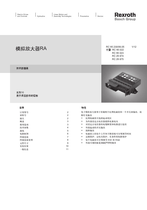
RC 66152/10.03 | LT RC 95 230/06.05 | RA 09
行走机械液压 /4 行走机械液压 | | 博世力士乐 /12
概述
模拟放大器最多可驱动两个比例电磁铁。控制电压在放大器中作为输入变量处理。模拟放大器提供一个可调电流,作为 比例电磁铁的输出变量。 通过输入端上最大设定点电压约5%的死区,可激活比例电磁铁的放大器输出端,也就是说,获得的是最小输出电流。使 用微调电位器,可分别调节最小输出电流在两个比例输出端的电平。如果输入端的设定点电压增加,每个相应的比例电磁铁 的输出电流会呈线性增加。 也可使用微调电位器分别调节最大输出电流。输出曲线的斜率会受此影响。 模拟放大器含有时间斜坡函数,可以使用这些函数来调整周期,使周期内的输出电流与修改后的设定点相匹配。斜坡时 间的调整范围在100 ms 至10 s之内。可使用微调电位器分别调整各个电磁铁的时间斜坡函数。
电位器 1
电子电路 电源
在RA1-0/10模拟放大器上, 只可提供此线以上的接线端
差分 输入2 电位器 2
PWM
输出端 电源
PWM 2
比例电磁铁
并行式
开关输入
开关输出端
切换PWM 频率(参见表)有 3 种连接选择:100 Hz、200 Hz 350 Hz(需要时) 可将电磁铁至电池(或底盘)的接地回路线接至电池(或底盘) 3) 电磁铁地线单独连接电池(或底盘) 4) RA1-0为3A
特性
电子模拟放大器用于控制两个比例电磁铁和一个开关量输出,故 障灯光输出 - 比例电磁铁可选择起动死区 - 为外部设定点电位器提供电源电压 - 对设定点电位器的电缆断裂和短路进行监控 - 外部起动的开关输出 - 故障输出 - 电磁铁上的每个上升和下降斜坡可分别调节时间 - 过载保护,过电压保护,有条件的短路保护 - 每个电磁铁可分别调节 Imin 和 Imax - 外部可调的脉宽调制(PWM)频率
力士乐伺服阀放大器说明书
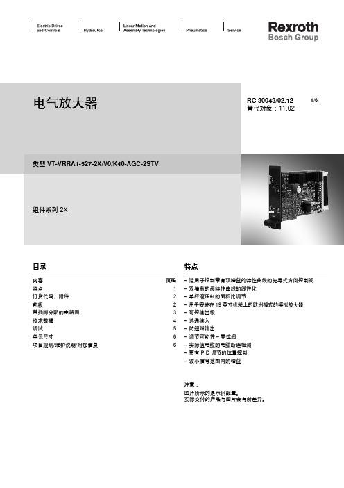
电气放大器类型 VT-VRRA1-527-2X/V0/K40-AGC-2STV组件系列 2XRC 30043/02.12替代对象:11.02目录内容 页码特点1订货代码,附件 2前板2带插脚分配的电路图 3技术数据 4调试 5单元尺寸6项目规划/维护说明/附加信息6特点– 适用于控制带有双增益的特性曲线的先导式方向控制阀– 双增益的阀特性曲线的线性化– 单杆液压缸的面积比调节– 用于安装在 19 英寸机架上的欧洲格式的模拟放大器– 可控输出级– 选通输入– 防短路输出– 调节可能性 – 零位阀– 实际值电缆的电缆断连检测– 带有 PID 调节的位置控制– 较小信号范围内的增益注意:图片所示的是示例配置。
实际交付的产品与图片会有所差异。
1/6订货代码,附件前板首选类型放大器类型材料编号用于带电气位置反馈和弯折的特性曲线的先导式方向控制阀VT-VRRA1-527-20/V0/K40-AGC-2STV08114050684WRL 10...35 V/V1...P-3X...4WRL 10...25 V/V1...P-3X...-750液压组件:用于具有电气反馈的阀 = R阀类型:方向控制阀 = R控制模拟= A选件K40-AGC-2STV = 在40%位置处双增益的先导式方向控制阀客户定制型号 V0 =标准样本型号2X =组件系列 20 至 29(20 至 29:技术数据和插脚分配不变)以下类型的序列号:527 =先导控制阀规格 6单杆液压缸的面积比调节较小信号范围内的增益粗调节精确调节VT-V RR A 15272X V0K40-AGC-2STV配套的板卡插槽:– 开放式板卡插槽 VT 3002-1-2X/32F (请参阅样本 29928)。
仅限用于控制柜安装!0带插脚分配的电路图控制零位控制零位电位计电源启用信号输入错误技术数据(有关这些参数之外的应用,请务必向我们咨询!)在 z2 – b2 处的电源电压 UB 公称电压 24 V =,电池电压 21…40 V,整流后的交流电压 Ueff= 21...28 V(单相,全波整流器)单独在 z2 – b2 处的滤波电容器建议:电容模块 VT 11110(请参阅样本 30750)(只有当 UB的波动值 > 10 % 时方可使用)阀线圈最大值 A/VA 2.7/40(先导控制阀规格 6)最大电流消耗 A 1.7电流消耗可能会随 最小 UB和到控制线圈的极限电缆长度增加功耗(典型值) W37输入信号(控制值)b20:0...±10 Vz20:0...±10 V }差动放大器(Ri= 100 kΩ)信号源b32,z32(10 mA)的电位计 10 kΩ,电源 ±10 V 或外部信号源启用输出级在 z16,U = 8.5...40 V,Ri= 100 kΩ,前板上的 LED(绿色)亮起位置传感器电源b30:–15 Vz30:+15 V先导控制阀实际值信号b22:0...±10 V实际值参考位b24主级实际值信号b26:0...±10 V实际值参考位b28线圈输出b6 – b8 I最大定时电流控制器2.7 A放大器与阀之间的电缆长度线圈电缆: 20 至 20 m 1.5 mm220 至 60 m 2.5 mm2位置传感器: 4 x 0.5 mm2(已屏蔽)主要特点 实际值电缆的电缆断连防护,带有 PID 调节的位置控制,脉冲输出级,具有较短启动时间的快速通电和快速断电,防短路输出,双增益流量特性曲线的线性化调节 零电位通过微调电位计 ±5 % 进行调节,单杆液压缸的面积比调节,较小信号范围内的增益LED 显示 绿色: 启用,黄色: 电缆断连实际值,红色: 欠电压(UB过低)错误消息– 电缆断连实际值– UB 过低– ±15 V 稳定z22:集电极开路输出到 +UB 最大 100 mA;无错误:+UB电路板格式 mm(100 x 160 x 大约 35)/(W x L x H)使用前板为 7 TE 的欧洲格式插入式连接连接器 DIN 41612 – F32环境温度 °C0...+70存储温度范围 °C–20...+70重量 m0.39 kg注意:电源零位 b2 和控制零位 b12 或 b14 或 z28 必须单独通向中心接地(零点)。