Air Torque一体式智能比例阀操作说明书
艾辛TM比例阀与整合放大器系列安装与启动指南说明书

Installation and start-up guidelines for Eaton TM proportional valves with integral amplifiersKBD/TG4V-3 and KBDG5V-*-11 Series1. lntroduction1.1 T he Eaton™ “KB-D/T” range of proportional valvesallow direction and rate of hydraulic fluid flow ina system to be controlled by a voltage commandsignal applied directly to the integral amplifier.It is not necessary to make any adjustments to the valve/ amplifier assembly prior to putting it into service either on a new installation or when replacing a valve on an existing installation.1.2WARNING: This valve with its integral electronic amplifier was factory tested prior to dispatch for conformance to the catalogued specification and performance data but Eaton Hydraulics warranty may be nullified by such actions as:•Dismantling or adjusting of any part of the assembly other than may be indicated in this leaflet.•Incorrect installation.•Application of the valve outside its catalogued performance limits.•Incorrect electrical connections.•Incorrect electrical control signals.1.3 B efore installing the valve check that the modeldesignation on the nameplate shows it to be thecorrect valve for the application.1.4 F or further information* P roportional Valves with Integral Amplifiers seecatalogs V-VLPO-MC001-E1, V-VLDI-MC014-E1.2. Valve for new application2.1 Installation2.1.1 T he valve can be mounted in any attitude but thepiping must be arranged to ensure that the valve iskept full of fluid at all times.2.1.2 D o not remove the protection pad on the bottomface of the valve until immediately beforeinstallation. Take care not to lose the seals from the valve ports. ensure that the surface on which thevalve is to be mounted is clean and free from burrs and damage. This applies also to any intermediate“stacking/sandwich” valves which may be used. 2.1.3 S ize 03 valves have a locating pin between portsP & B in their bottom face. This ensures that thevalve is correctly oriented on the mounting face,which should contain a mating hole.2.1.4 I nstall the valve and any intermediate “stacking/sandwich” valves on the mounting surface andsecure them with bolts to class 12.9 (ISO 898)or better. Torque bolts according to the followingrecommendations. For details of available Eaton TMbolt kits see catalog 2314A “Fixingbolt kits”.VALVE Clamping height Bolts/studs for mounting surface mm (in)ISO 4401(torque)ANSI/B93.7M(torque)KBD/T-321 (0.82) 4 x M5-6g(7-9 Nm)4 x #10-24 UNC-31(962-76 lbf in)KBDG5V530(1.18) 4 x M6-6g 4 x 1/4" - 20 UNC-3A KBDG5V733 (1.3) 4 x M10 4 x 3/8” - 16 UNC KBDG5V842,5 (1.67) 6 x M12 6 x 1/2" - 13 UNC KBDG5V1035 (1.38) 6 x M20 6 x 3/4" - 10 UNC-28• Minimum actual bolt lengths are the sum of relevant clamping heights plus the minimum engagement lengths in ferrous materials - see table below:MetricBolt size Min. EngagementInchBolt size Min. EngagementM510 mm#10-240.39”M610 mm1/4”0.39”M1013 mm3/8”0.52”M2035 mm3/4” 1.38”2Installation and start-up guidelines for vickers proportional valves with integral amplifiers E-VL VI-II001-E May 2021 2.1.5 Electrical ConnectionsBefore starting to connect cables ensure that all power is switched off. Electrical connections must be made via the 7-pin plug mounted on the amplifier.The recommended cable should have at least 6 cores with pairs of conductors individually screened and an overall braided screen.A suitable product is offered by RS components (stock No 368-390) and consists of 3 pairs of 7/0.254 mm 2 (22 AWG) and one pair of 7/0.32 mm 2 (20 AWG) plain copper conductors with polyethylene insulation. each pair iswrapped in an aluminized tape. The pairs are placed around a central drain wire with a tinned copper overall braid and gray PVC sheath (10 mm overall dia).10V24V 18V 24V (H)12m 24m0mCable lengthM i n i m u m p o w e r s u p p l y16VFor additional wiring Information, see installation & wiring guidelines GB-2468A.Command signals and outputs7-pin plug Flow direction Command=Volts(±10V)Pin D Pin E Positive OV P to AOV Negative V D V E = PositiveNegative OV P to BOVPositiveV D V E = Negative Pin DPin B Pin E Flow direction Command =Current (4-20 mA)More than 12 mA Current GND Current return P to A Less than 12 mACurrent GNDCurrent returnP to BWARNINGTo conform to the requirements of the Europeancommunity directive on Electromagnetic Compatibility (EMC) the valves with integral amplifiers must be fitted with a metal plug. Suitable plugs are:1) Eaton TMpart no. 934939 which also gives environmental protection to IP67 when tightened with a torque of 2-2,5 Nm (1.5-2.0 lbf ft).2) ITT -Cannon part no. CA 06 COM-E 14S A7 S (not available from eaton hydraulics).The plastic plug part no. 694534 is only suitable for use in a sealed electromagnetic environment or outside of the European Community.Plug assembly instructionsThe metal 7-pin plug part no. 934939 must be usedwith this valve to achieve the full EMC specification. The assembly of the plug ls as shown in the diagram.Assembly instructions for plastic plug part number 694534housing assembly(viewed on wiring side)Wiring assembly procedure1. Lead the cable through items a, b, c, d and e.2. Make soldered connections to plug terminals:Pin A Power supplyPin B Power supply 0V and current command return Pin C Enable input (PH7 & PR7 options)Pin D Command signal (+V or current in)Pin E Command signal (-V or current GND)Pin F Output monitor Pin G Protective ground 3. Push cable clamp (e) into contact assemblyhousing (f) and tighten damp screws.4. Screw body (d) Into (f) and tighten.5. Push rubber grommet (c) and washer (b) intobody (d)6. Thread clamp nut (a) into body and tighten tofirmly clamp the cable.7. The plug assembly can now be connected tothe amplifier.Figure 1. Wiring connections for valves withintegral amplifierPin C may be connected to ground or left unconnected.Figure 2. Wiring connections for valves with “Enable” feature• Output monitor voltage (pin F) will be referenced to the KBpower 0 volts (pin B).ote:N In applications where the valve must conform to European RFI/EMC regulations, the outer screen(shield) must be connected to the outer shell ofthe 7- pin connector and the valve body mustbe fastened to the earth ground. Proper earthgrounding practices must be observed in this case,as any differences in command source and valveground potential will result in a screen (shield)ground loop.2.1.6 Power and signal levelsPower supply ..........24V DC (22 to 36Vincluding 10% peak-to-peak ripple) Command signal .....+/-10V or 4-20 mA(model code option)Monitor signal .........H option coil = 1.7V per amp solenoidcurrent output impedance 10 kΩ2.2 Start-up2.2.1 Single-stage valves1. Switch power on.2. The valve response to a command signal can bemonitored via the connection from plug pin F (for pin F voltages, see 2.1.6). If monitor signal does not follow command signal, check command signal connections to amplifier.2.2.2I t is advisable to bleed air from the solenoidsof these valves. slacken bleed screws (counter-clockwise) until fluid starts to escape. Allow fluid tocontinue to escape until it is seen to be free of airbubbles. The higher the pressures at the tank port,the faster this process.††† Bleed screw locations.Re-tighten the screws to the following torque values:6,5 - 7,5 Nm (57-66 lbf ft).2.2.3 Two-stage valvesThe procedure for bleeding the air for the single stage valves (section 2.2.2 above) can be applied to the two stage valves provided that the valve is supplied with hydraulic pilot pressure.EX models (external Pilot supply):pressure at X port = 50 bar (725 psi) minimumX models (internal pilot supply):pressure at P port = 50 bar (725 psi) minimum3. Replacing an existing valve3.1 Installation3.1.1 T he following are advisory and may not be applicableto specific systems or applications. The user mayneed to establish procedures to suit the application. WARNING· Before removing an existing valve:•Tum off all electrical power.•Relieve hydraulic pressure. Accumulators must either be isolated from the system by suitable valves or the hydraulic fluid discharged to the reservoir.•Any overhead or positive head reservoirs must be isolated from the system by suitable valves.•Lower all vertical cylinders•Block any cylinders whose movement could generate pressure.3Installation and start-up guidelines for vickers proportional valves with integral amplifiers E-VL VI-II001-E May 2021 3.1.2 D isconnect electrical plug from the valve.3.1.3 B efore removing valve, make provision to prevent anyhazard arising from fluid that will drain from exposedmounting surfaces.3.1.4 U nscrew the valve mounting bolts, removing theseand the valve. Keep the valve mounting surface clearof any contamination whilst draining all fluid from it.If returning the valve to Eaton Hydraulics for repair,fit the protection plate from the new valve afterensuring that all fluid has been drained.3.1.5 A s 2.1.1.3.1.6 A s 2.1.2.3.1.7 I nstall the new valve using the existing bolts andelectrical plugs if in good condition. If not, referto sections 2.1.4 and 2.1.5 respectively.3.2 Re-start-up3.2.1 R estore the application to its state immediatelyprior to section 3.1.1.3.2.2 A fter initial start-up of the repaired system,bleed the new valve as in section 2.2.2.3.2.3 P roceed as for new valve (sections 2.2.1).4. Ramp adjustment4.1 T he ramp adjustment feature is accessedby removing the amplifier lid.ote:N Before adjusting the ramp setting ensure that precautions are taken to prevent static dischargeharming the amplifier.Ensure that the amplifier lid seal is not damagedor lost during adjustment.4.2 I n normal operation the amplifier status LEDwill flash. To activate the RAMP adjustmentmode:1. Select button2. Ramp increase button3. Ramp decrease button4. Status LED - green5. Store LED - red6. Ramp increase/solenoid operation LED - green7. Ramp decrease/solenoid operation LED - green Adjustment NotesPress Select button (1)The amplifier is now able to acceptadjustments to the ramp rate. TheStatus LED will stop flashing duringthis adjustment mode.Adjust the ramp rate by using eitherthe Ramp Increase (2) or RampDecrease (3) buttonsThe Ramp LEDs will illuminate as theRamp Increase or Ramp Decreasebuttons are activatedWhen the ramp adjustment iscomplete press the Select button (1)to store the ramp adjustmentThis enters the adjusted RampValues into the amplifier memory.The Status LED will begin flashing toindicate that normal operating modehas been resumed.ote:N If you wish to exit the ramp adjustment mode without storing the ramp settings then switch offpower to amplifier. the amplifier will return topreviously stored settings.4.3 W hen refitting the amplifier lid ensurethat the seal is fitted correctly and is notdamaged. The amplifier lid screwsshould be tightened to 0,7-0,9 Nm4Installation and start-up guidelines for vickers proportional valves with integral amplifiers E-VL VI-II001-E May 2021 Installation and start-up guidelines for vickers proportional valves with integral amplifiers E-VL VI-II001-E May 2021 5EatonEMEA Headquarters Route de la Longeraie 7 1110 Morges, Switzerland Eaton.eu© 2021 EatonAll Rights Reserved Printed in USDocument No. E-VLVI-II001-E May 2021Eaton is a registered trademark.All trademarks are propertyof their respective owners.Changes to the products, to the information contained in this document, and to prices are reserved; so are errors and omissions. Only order confirmations and technical documentation by Eaton is binding. Photos and pictures also do not warrant a specific layout or functionality. Their use in whatever form is subject to prior approval by Eaton. The same applies to Trademarks (especially Eaton, Moeller, and Cutler-Hammer). The Terms and Conditions of Eaton apply, as referenced on Eaton Internet pages and Eaton order confirmations.。
全自动胶带阀门的neumatische-aktuator-brochure说明书

The basic options and accessories listed in this section represent many of the most commonly used for Pneumatic actuation of Pneumatic Diaphragm Valves (see previous section for Pneumatic Ball Valves and ButterÀ y Valves). Contact Spears® for any desired accessories, options, functions, or special controls not listed. For differentiation, “Option” is used to identify a basic variation in the actuator while “Accessory” is used to identify an add-on function to the actuator. Both options and accessories are factory con¿ gured to order on the actuation package.Overview of Basic Options & Accessories AvailablePneumatic Actuator Features Premium Pneumatic Diaphragm ValvesSpring Return Option80 psi Operating Pressure StandardDeclutchable Manual Override2-1/2 & LargerPneumatic Positioner Air-to-Spring not Air-to-AirElectro-Pneumatic Positioner Air-to-Spring not Air-to-AirMicro Limit Switch Module Accessory3 & 4-Way Solenoid Valve AccessoryStainless Steel 3-Gauge Set AccessoryID Tag - SS AccessoryContact Spears® for any desired accessories, options, functions,or special controls not listed in this guide.Spring Return (Fail Safe)(Air-to-Open or Air-to-Close) OptionAvailable for all Premium Pneumatic actuated valves.An internal spring in the actuator is con¿ gured to eitheropen or close upon loss of air supply. Spring return can be speci¿ ed as either Air-to-Open when spring return close is desired or Air-to-Close when spring return open is desired.Operating Pressure(for Diaphragm Valves)Spears® Diaphragm Valves use a 80 psi standard, 40 psi - 60 psi optional operating pressure. Specify pressure requirements at time of order.3 to 15 psi PneumaticPositioner(for Diaphragm Valves)Available for all Premium Pneumatic actuated Diaphragm Valves. Positioner is used to control or throttle À ow by modulating the air to the actuator in response to an external 3-15 psi control signal input. Available with NEMA 4x enclosure mounted on top of actuator with 180° visual indicator. Positioner can be top or bottom loading, with or without gauges. Gauge set includes: 1 input pressure gauge 0-30 psi and 2 output pressure gauges 0-160 psi. Optional StainlessSteel gauge set available.PNEUMATIC ACTUATOR OPTIONS & ACCESSORIESFor Diaphragm ValvesElectro-Pneumatic Positioner (for Diaphragm Valves),not for air-to-air 4 to 20 mAAvailable for all Premium Pneumatic Actuated Diaphragm Valves. Positioner is used to control or throttle À ow by modulating the air to the actuator in response to an external 4-20 milliamp control signal input which is converted to a proportional 3-15 psi pneumatic signal used by the positioner. Available with NEMA 4x, enclosure mounted on top of actuator with 180° visual indicator. Used with air-to-spring onlyMicro Limit Switch Module (for Diaphragm Valves)SPDT (2) or DPDT (2)Available for all Premium Pneumatic Actuated Diaphragm Valves. Module of two (2) auxiliary mechanical limit switches. Switches are SPDT rated at 10 amp 125/250 V AC. Switch module includes 180° visual indicator. Switch enclosure is NEMA 4/4x/7/9 rated.3-Way Solenoid Valves 4-Way Solenoid Valves (for Diaphragm Valves)Available for all Premium Pneumatic Actuated Diaphragm Valves. Universal operation design allows pressure to any port. 4-way solenoid valve is used for double acting (air-to-air) actuators. 3-way solenoid valve is used for spring return (fail open/fail close) actuators. Air inlet is 1/4" NPT. Enclosures are molded epoxy NEMA 4, 4x (standard) or NEMA 4/4x/7/9 combination with 1/2" conduit connection and brass body (stainless steel body available by special order). Standard 115 V AC with voltage options of 230 V AC, 24 V AC, 12 VDC, and 24 VDC.Custom ID TagStainless steel valve/actuator ID Tag imprinted to user speci ¿ ed identi ¿ cation criteria. Each tag is 1/2" x 3"and accommodates up to 3 lines of text, maximum of12 characters and spaces per line.PNEUMATIC ACTUATOR OPTIONS & ACCESSORIESFor Diaphragm Valves。
阿尔法拉瓦尔LKC超纯值一体化控制 检查阀说明书
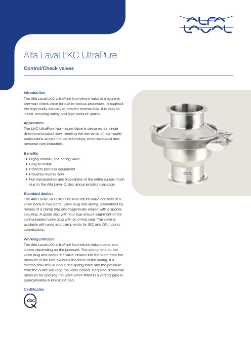
valve body in two parts, valve plug and spring, assembled by means of a clamp ring and hygienically sealed with a special seal ring. A guide disc with four legs ensure alignment of the spring-loaded valve plug with an o-ring seal. The valve is available with weld and clamp ends for ISO and DIN tubing connections.Working principleThe Alfa Laval LKC UltraPure Non-return Valve opens and closes depending on the pressure. The spring acts on the valve plug and keeps the valve closed until the force from the pressure in the inlet exceeds the force of the spring. If a reverse flow should occur, the spring force and the pressure from the outlet will keep the valve closed. Required differential pressure for opening the valve when fitted in a vertical pipe is approximately 6 kPa (0.06 bar).CertificatesTECHNICAL DATAMax. product pressure:1000 kPa (10 bar)Required differential pressure for opening the valve when fitted in a vertical pipe, is approx. 6 kPa (0.06bar).ASME BPE designation:SF3External:Ra < 0.8 µm Internal:Ra < 0.5 µm ASME BPE designation:SF1External:Ra < 0.8 µm 1This equipment is outside the scope of the directive 2014/34/EU and must not carry a separate CE marking according to the directive as the equipment has no own ignition sourcePHYSICAL DATAProduct wetted steel part:Acc. to EN 10088 or equal (AISI 316L)Other steel parts: 1.4301 (304)Acc. to AISI 304Spring:Electropolished Product wetted elastomer:Acc. to FDA and USP Class VI Temperature: -10°C - 140°C Product wetted elastomer:FPMAcc. to FDATemperature: -10°C - 180°C Weld ends:Acc. to ISO or DINClamp ends:Matching tubes and fittings: ISO 2037 / Series A/DIN Acc. to ISO or DINPressure drop/capacity diagramsP (kPa)Q (m³/h)A = DN25; ISO25B = DN32/40; ISO38C = DN50; ISO51D = DN63; ISO63.5E = DN80; ISO76.1F = DN100; ISO101.6Note! For the diagram the following applies:Medium: Water (20°C).Measurement: In accordance with VDI 2173.Figure 1. 1 = Flow direction.Shows the optimal built-in situation to make sure the valve is drainable. The four guide legs of the valve cone ensure good alignment.90°rotation.Dimensions (mm)TD 900-563This document and its contents are subject to copyrights and other intellectual property rights owned by Alfa Laval Corporate AB. No part of this document may be copied, re-produced or transmitted in any form or by any means, or for any purpose, without Alfa Laval Corporate AB’s prior express written permission. Information and services provided in this document are made as a benefit and service to the user, and no representations or warranties are made about the accuracy or suitability of this information and these services for any purpose. All rights are reserved.200002789-1-EN-GB© Alfa Laval Corporate AB How to contact Alfa LavalUp-to-date Alfa Laval contact details for all countries are always availableon our website at 。
比例阀使用说明
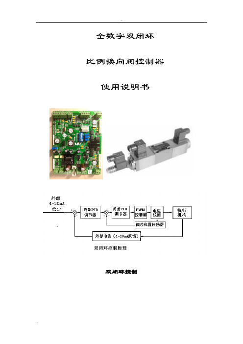
全数字双闭环比例换向阀控制器使用说明书双闭环控制一、概述电路采用32bit高速CPU设计,具有结构简单可靠,参数长时间不会漂移,看门狗设计。
具有模拟量和数字量外部接口设计。
一块控制板可以方便控制比例换向阀,大大简化了常规设计。
二、功能特点1、集成双闭环设计,比例换向阀阀芯位置闭环控制\外部给定反馈闭环控制2、放大器和控制器合二为一,精简设备,减少维护量降低故障率3、具有使用模拟量接口4-20mA(或者0-20mA)反馈、4-20mA(或者0-20mA)(给定与主电路隔离)4、具有数字量接口设计,MODEBUSRS485RTU、CANBUS接口5、可以多个设备进行组网控制,适合多点集中控制6、外部给定反馈闭环控制PID参数调节通过3个电位器调整7、两路阀芯电磁铁控制具有输出过流保护8、看门狗设计,能够及时复位异常工况三、参数1、供电:DC15~30VDC @ 2A2、尺寸123(mm)X160(mm)3、调节精度±1%4、适用范围:华德比例换向阀6通径或10通径带阀芯位置反馈装置进行液压缸、液压缸伸缩位置定位控制,马达行走机构定位控制,液压升降机构定位控制,液压紧紧力装置控制、液压马达行走速度控制等5、工作温度:-30~60摄氏度6、湿度:7、震动:四、典型应用执行机构可以是液压缸,液压马达等执行部件,可以对控制对象进行精准控制五、接线说明六、调整方法此步骤为出厂已经调试好,一般用户无需调整,如果参数确实差异很大,请谨慎操作1、按照接线方法接好线,并认真检查正确后,将控制板上的保险丝去掉,控制板上电后,用万用表的交流档测量COM与L 和COM与R的电压应相同大约在2.3VAC,如果差异大(>0.1VAC)就需要松开位置传感器上的螺丝,将位置传感器的位置通过两个限位螺丝移动,直到测量COM与L 和COM与R的电压应相同为止。
这个步骤一般用户只做检查即可,已经出厂调整过。
如果确实差异很大就必须进行调整。
比例阀中文说明书

①同时摁下达 3 秒以上
■ 使用注意事项
! 注意
1. 本产品,在控制状态时,由于停电等异常情况引起电源被切断,能在短时间内保持 2 次侧的出口压力。 当 2 次侧为大气开放的状态时,停电后空气还会继续排放,使用时请充分注意。
2. 本产品,在通电状态下停止供给压力时,内藏的电磁阀持续动作,可能会引发噪声。当停止供气时,请 务必同时切断电源。
电流型 电压型
4~20mADC (ITV10※※-01,ITV20※※-01,ITV30※※-01) 0~20mADC (ITV10※※-11,ITV20※※-11,ITV30※※-11) 0~5VDC (ITV10※※-21,ITV20※※-21,ITV30※※-21) 0~10VDC (ITV10※※-31,ITV20※※-31,ITV30※※-31)
质量
约 250g(无附属品){ITV1000}
约 350g(无附属品){ITV2000}
约 620g(无附属品){ITV3000}
注1) 输出压力 0.1MPa 规格最大供给压力为 0.2MPa。
注2) 超出规格范围时,会发生破损,请注意。
3
■ 配线方法 电缆与本体的端子连接时,请以下记的形式进行配线。
输出压力% 输出压力%
输入信号
输入信号
■ 显示输出
显示用的输出电压依据下表所示。本产品所连接的计测器件,其所使用的负载阻抗请确保在 1kΩ 以上。另
外,此输出电压需增幅使用时,请同样考虑设计负载阻抗在 1kΩ 以上。
型号
输出压力(MPa)
显示用输出电压(VDC) 注)
ITV※01※-※1
0.005~0.1
1各部分名称外形尺寸安装孔up键键配线电缆接线端子设定键set键down键键安装托架选配右弯出线型电缆接线端子显示用led4芯sup接口压力表用接口out接口外形尺寸安装孔安装孔安装托架安装托架选配选配直线出线型电缆接线端子4芯右弯出线型电缆接线端子4芯安装孔2规格供给压力注1设定压力01mpa但最大为1mpa000501mpaitv1011itv2011itv3011设定压力000505mpaitv1031itv2031itv3031000509mpaitv1051itv2051itv3051约200lminanritv1000供给压力
比例阀说明书范文

比例阀说明书范文比例阀是一种可以根据输入和输出的信号,来调节流体介质流量的装置。
它可以根据需要自动调节流量,使系统能够按照设定值工作。
下面是一份比例阀的说明书。
一、产品概述比例阀是一种用于控制流体介质流量的装置,它通过调节阀芯的开启度来控制流量大小。
比例阀通常由电磁铁、阀芯、弹簧、流量控制电路等部件组成。
电磁铁通过接收输入的电信号,控制阀芯的开启度,进而调节流量大小。
二、产品特点1.控制精确:比例阀采用开环控制,可根据输入信号调节阀芯开启度,使流量精确控制在设定值范围内。
2.反应迅速:比例阀采用电磁铁控制阀芯,电磁铁响应速度快,能够迅速调节阀芯开启度,实现流量的快速调节。
3.耐高压:比例阀采用优质材料制成,能够承受较高的压力,保证工作的稳定性和安全性。
4.耐腐蚀:比例阀采用耐腐蚀材料制成,可以适应各种腐蚀介质的控制,延长使用寿命。
5.体积小巧:比例阀体积小巧,安装方便,可以根据需要进行空间布局。
三、产品应用领域比例阀可广泛应用于以下领域:1.工业自动化控制系统:比例阀可用于控制各种工业流体介质,如液体、气体等,实现流体流量的准确控制。
2.压力控制系统:比例阀可根据输入的压力信号,控制流体介质的流量,保持系统内的压力稳定。
3.温度控制系统:比例阀可根据输入的温度信号,控制流体介质的流量,实现温度的精确控制。
4.液位控制系统:比例阀可根据输入的液位信号,控制液体介质的流量,实现液位的稳定控制。
四、产品使用方法1.安装:将比例阀安装在需要控制流量的管道上,注意连接的密封性和稳定性。
2.输入信号设置:根据实际需要,将输入信号连接到比例阀的控制电路上。
输入信号可以是电压、电流或者其他类型的信号。
3.设定流量范围:根据实际需要,调节比例阀的开启度,设定所需的流量范围。
4.系统调试:将比例阀接通电源,观察输出流量是否符合设定值,如有偏差可以进一步调节阀芯开启度。
五、产品维护与保养1.定期检查:定期检查比例阀的连接是否松动,电磁铁是否正常工作,阀芯是否磨损,如有异常情况及时进行维修或更换。
比例阀的调整说明
比例阀的调整说明比例阀是工业自动化过程中常用的一种控制阀,它的主要用途是调节流体介质的流量和压力,使得流体系统能够按照预定的比例工作,从而实现对工业过程参数的精确调控。
下面是比例阀的调整说明。
1.准备工作:在进行比例阀的调整前,需要先进行准确的参数设定。
这包括需要调整的流量、压力范围以及所需的精度等。
同时,还需要了解控制系统的工作原理和控制模式。
2.比例阀的调整步骤:(1)将比例阀安装到系统中,并正确连接好进出口管线。
(2)调整比例阀的调节参数,比如开度范围、零点漂移、灵敏度等。
这些参数通常可以通过阀体上的调节螺丝来进行微调,具体调整方法需要查看比例阀的说明书。
(3)进行初步调试。
打开系统控制开关,观察比例阀的实际工作情况,检查是否存在异常情况。
(4)根据系统的要求,对比例阀的调节范围进行进一步调整。
比例阀的调节范围是指阀门的最小和最大开度之间的比例关系,调整范围越大,阀门的控制精度就越高。
(5)进行性能测试。
将比例阀置于工作状态下,通过外部信号调节阀门的开度,观察管道中介质的流量和压力变化,检查比例阀的控制精度是否满足要求。
3.比例阀的故障排除:在进行比例阀的调整过程中,如果出现工作不正常的情况,需要进行故障排除。
常见的比例阀故障包括阀门无法开启或关闭、阀门卡死、阀门漏气等。
故障排除的方法通常包括以下几个步骤:(1)检查比例阀的电源是否正常,电压是否稳定。
(2)检查阀门是否受到堵塞或损坏,是否需要进行清洗或更换部件。
(3)检查比例阀所处的管线是否存在压力异常或泄漏现象,必要时需要修复或更换管线。
(4)通过仪器检测比例阀的开度和闭合情况,观察是否存在异常。
4.比例阀的维护与保养:为了确保比例阀的正常工作,需要进行定期的维护与保养。
具体包括:(1)清洗比例阀,去除积聚在阀门表面的污垢或杂质。
(2)定期检查比例阀的阀门动作是否灵活,需要加油或更换易损部件。
(3)检查比例阀的电源连接是否良好,电压是否稳定。
智能自控调节阀说明书
ZY-ETBL直行程系列总线型智能PID自控调节阀使用说明书无锡市振源自控仪表有限公司目录产品简介 (2)型号与规格 (2)主要参数 (2)内部电气及操作规程 (3)菜单结构与操作说明 (8)通信协议 (17)阀体结构和应用场合 (19)外形尺寸图表 (20)维护与安装说明 (24)附录:P、I、D整定方法 (26)一、产品简介ZY-ET-00系列PID自控调节阀,是具有自行调节功能的电动智能调节阀。
直接与传感器连接,组成最小范围的闭环系统,PID增量式算法,对流体进行调节。
既节省了调节仪表,又可省去繁琐的远距离布线。
如果您的系统需要由中控室监控,则可选用带有现场总线功能的ZY-ETB-00总线型自控调节阀,通过RS485的方式接入监控主机(本系列产品采用标准MODBUS RTU通信协议)。
本公司生产的直行程自控调节阀主要有以下几个品种:单座阀、套筒阀、双座阀、三通分流阀、三通合流阀、衬氟阀。
二、型号与规格自控智能型电动调节阀型号与规格如下所示。
三、主要参数1、电源,单相220V交流电源。
2、输入传感器种类,热电阻:Pt100、Cu100。
电流(电压):4-20mA(1-5V),或0-20mA范围内由用户定义。
3、环境要求,温度: -10℃-- +60℃(无加热器)相对湿度:≤95%周围空气中无腐蚀性介质4、配线:信号线采用屏蔽线,与电源线隔离。
规格为 S=1.5mm²,可安装保护套管PF3/4(G3/4)。
电源电缆线采用规格为S=1.5mm²电缆线。
通信电缆线采用1.5 mm²的双绞线,也可采用带屏蔽的双绞线。
5、输出电源,本机配备直流24V电源,额定功率8W,作为传感器的电源。
6、通信接口:RS485串行通信接口,标准Modbus RTU 协议。
(选购功能)四、内部电气及操作规程1、控制模块接口说明○1电源接线端子:220V单相交流电源。
○2输入、输出端子:传感器输入,24V电源输出,报警触点输出。
- 1、下载文档前请自行甄别文档内容的完整性,平台不提供额外的编辑、内容补充、找答案等附加服务。
- 2、"仅部分预览"的文档,不可在线预览部分如存在完整性等问题,可反馈申请退款(可完整预览的文档不适用该条件!)。
- 3、如文档侵犯您的权益,请联系客服反馈,我们会尽快为您处理(人工客服工作时间:9:00-18:30)。
一体式智能比例阀
●请仔细阅读本操作手册,然后正确使用●使用之前,请务必先阅读有关注意事项
(3)
(3)
请仔细地阅读下面的注意事项,并且严格遵守其中的每一条指令。
1word)
ID2(高八位)
)
按进入界面
继续按继续按
直到 Profibus 总线控制,此时再按会增加界面,可以选择PRESS ->FOR 3S
C:CONFIG
2.Profibus DP LED显示状态
PCB主板
电源接
口:建议
将PE口4.Profibus 系统电路连接
Sl
当定位器在断电或是发生意外情况下,在总线无法控制阀门时,需要
定位器的显示元件
向左向右键向下键向上键
初始化流程说明
P=0.0
a.若开机显示画面 , 系统进行初始化才能正常工
D:NO INIT
按
切换为0..20mA
:若换,出现
连接以后按住
3S
初始化完成,整个初始化过程需要返回界面
成功初始化之后增加界面:切换界面。
调节数值,
切换界面。
注意:当P=0.0
D: INIT OK
进入下一级
界面后按
切换的界面下按恢复默认值,切换为界面
后即退回到上级界面。
三、在初始化成功之后进行各项参数设定:
后按切换
3S进行初始
改变设定值方向
说明见参数说明中设定方向)
OFF,MIN/MAX, MIN/MIN
输出的设定。
LCD显示Min/Min AlarmFun
调节10-100,。
设置报警的最大位置。
ERR+RAN, RANGE
0-100S。
设置错误时间,即达到错
误等级所需要的时间。
错误等级的选择,当错误选项被选择,必须在错误时间内达到错误等级设置的误差内,否则,进行错误输出。
选择错误范围。
即输入信号低于/高于范围报警。
Range
Error
按
(详细说明见参数说明中最小位置和最大位置)
按
值为100。
(详细说明见参数说明中
最小位置和最大位置)
no/min/max/min&max
为阀门排气至最小位置时实现阀门紧闭,
67.6 94.9
100 100
4 5.67.2
调节0.1-10.0,默认值
5.0。
oltage,设定反馈值
设置反馈值点,同时按
百分比设定和电压或电流值设定。
每设定完一个点之后按出现界面
再按回到界面
定,依次进行下去。
最多
按进入下一界面。
设置执行器开启的响应时间,默
认值为6
调节3.3-10.0。
设置执行器关闭的响应时间,默认值为
4.0。
值为10.0
以下会导致阀门动作速度过慢而无法动作,建
ON。
选择液晶自动跳转和屏幕锁定
分钟后会跳转到界面
设置
0-100
位器控制
会增加界面总线地址选择,默认为86,可以选择
≤0.3% 可调
通过按 或 键,然后再按 键(至少
器可重新设定进入“DEFAUL”状态。
在进入“DEFAUL T”状态后,定位器必须重新初始化。
时,初始状态为最小量程阀门处于未充气关闭状态,
设定值方向也可反向的设定,定位器尺寸图
检查并排除故障。