户外机柜IPX55指导书
别墅低压配电柜操作作业指导书
别墅低压配电柜操作作业指导书1. 操作前的准备工作在进行别墅低压配电柜操作前,有几项重要的准备工作需要完成:1.1 熟悉配电柜的结构和功能在开始操作前,需要对别墅低压配电柜的结构和各部件的功能有一定的了解。
熟悉配电柜的结构有助于正确操作和维护。
1.2 确定配电柜的断电状态在进行任何操作前,务必确认配电柜已经断电并且完全处于离线状态。
这是保证操作人员安全的重要步骤。
1.3 携带必要的工具和设备在进行操作前,应检查并准备好必要的工具和设备,如螺丝刀、电钳、绝缘手套等。
确保所有工具和设备的良好状态,以确保操作的顺利进行。
2. 操作步骤通过合理的操作步骤,可以确保对别墅低压配电柜进行安全、高效的操作。
2.1 打开配电柜的门使用合适的工具(如螺丝刀)打开配电柜的门。
注意在操作过程中避免对配电柜造成损坏,并确保自身安全。
2.2 检查电源是否已完全切断在进入配电柜之前,应确认配电柜的电源已经完全切断。
可以通过观察电源指示灯或使用电压表等方法来验证。
2.3 检查电源线路和连接器的状况在进行任何操作前,应检查电源线路和连接器的状况。
确保电源线路无损坏、无短路,并确保连接器的稳固性。
2.4 检查配电柜内部的状况进入配电柜后,应仔细检查配电柜内部的状况。
确保没有异物、积尘等物质存在,确保线路接触良好。
2.5 进行必要的操作根据实际需要,进行必要的操作。
如插拔电源线路、更换保险丝等。
在进行操作时,务必遵循安全规范,并确保操作的准确性。
2.6 关闭配电柜的门在操作完毕后,应将配电柜的门恢复到原来的关闭状态。
确保门能够完全关闭,并注意防止夹损自身。
3. 操作安全注意事项在进行别墅低压配电柜操作时,需要注意以下安全事项:•确保操作人员具备相关的电气知识和技能,不懂的操作咨询专业人员。
•操作前确认配电柜已经断电,并使用正确的工具操作。
•避免在潮湿的环境下进行操作,以防触电事故发生。
•注意自身安全,佩戴绝缘手套等个人防护装备。
•遵循操作顺序,按照正确的步骤进行操作。
Series NRX IP55 防尘防水封闭式电路保护器安装说明说明书
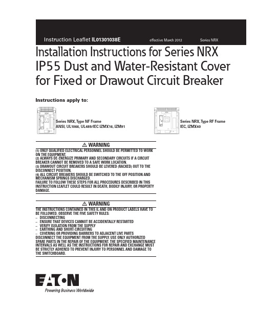
IP55 Dust and Water-Resistant Cover for Fixed or Drawout Circuit Breaker• WARNING(1) ONLY QUALIFIED ELECTRICAL PERSONNEL SHOULD BE PERMITTED TO WORK ON THE EQUIPMENT.(2) ALWAYS DE-ENERGIZE PRIMARY AND SECONDARY CIRCUITS IF A CIRCUIT BREAKER CANNOT BE REMOVED TO A SAFE WORK LOCATION.(3) DRAWOUT CIRCUIT BREAKERS SHOULD BE LEVERED (RACKED) OUT TO THE DISCONNECT POSITION.(4) ALL CIRCUIT BREAKERS SHOULD BE SWITCHED TO THE OFF POSITION AND MECHANISM SPRINGS DISCHARGED.FAILURE TO FOLLOW THESE STEPS FOR ALL PROCEDURES DESCRIBED IN THIS INSTRUCTION LEAFLET COULD RESULT IN DEATH, BODILY INJURY, OR PROPERTY DAMAGE.• WARNINGTHE INSTRUCTIONS CONTAINED IN THIS IL AND ON PRODUCT LABELS HAVE TO BE FOLLOWED. OBSERVE THE FIVE SAFETY RULES: – DISCONNECTING– ENSURE THAT DEVICES CANNOT BE ACCIDENTALLY RESTARTED – VERIFY ISOLATION FROM THE SUPPLY – EARTHING AND SHORT-CIRCUITING– COVERING OR PROVIDING BARRIERS TO ADJACENT LIVE PARTSDISCONNECT THE EQUIPMENT FROM THE SUPPLY. USE ONLY AUTHORIZEDSPARE PARTS IN THE REPAIR OF THE EQUIPMENT. THE SPECIFIED MAINTENANCE INTERVALS AS WELL AS THE INSTRUCTIONS FOR REPAIR AND EXCHANGE MUST BE STRICTLY ADHERED TO PREVENT INJURY TO PERSONNEL AND DAMAGE TO THE SWITCHBOARD.Instructions apply to:Series NRX, T ype NF FrameANSI, UL1066, UL489/IEC IZMX16, IZM91Series NRX, T ype RF FrameIEC, IZMX402Installation Instructions for Series NRX IP55 Dust and Water-Resistant Cover for Fixed or Drawout Circuit BreakerEATON CORPORATION Instruction Leaflet IL01301038Eeffective March 2012Section 1: General informationThe IP55 dust and water-resistant cover is a translucent hinged dome-shaped cover that attaches to the metal compartment door (panel) to provide dust and water protection for a drawout or fixed circuit breaker in keeping with the IP55 code. The specific code defines the degree of protection against the ingress of solid foreign objects and water.Note: The IP55 cover is used in conjunction with a door escutcheon, which is a molded frame and gasket used to seal the space between the circuit breaker and the compartment door cutout. If an escutcheon is not already installed, an escutcheon kit will have to be installed before the IP55 cover can be used. Refer to IL01301012E for door escutcheon installation details.Note: The existing enclosure must qualify to IP55 requirements for dust and water environments.Required tools• Phillips head screwdriver (#2 recommended)• Drill• 0.265-inch (6.5 mm) drill bit • Small adjustable wrenchKit parts identificationRefer to Figure 1 for visual identification of the parts listed below.(A) IP55 cover with captive hardware (one)(B) Hinge pin (one)(C) Hinge block (two)(D) Hex standoff (NF - two; RF - four)(E) M6 x 20 screw (four)(F) M6 x 8 screw (NF - two; RF - four)(G) M6 hex nut (four)(H) M6 split-ring lock washer (four)Figure 1. Kit ContentsSection 2: Installation of IP55 coverStep 1: Locate and drill the 0.265-inch (6.5 mm) diameter mountingholes in the compartment door (panel) relative to the already mounted door escutcheon as shown. Two holes are required for the NF frame and four holes are required for the RF frame.ote:N The exact mounting hole locations are determined by whether the circuit breaker is a fixed or drawout configuration.(A)(C)(D)(B)(E)(F)(G)(H)3Instruction Leaflet IL01301038Eeffective March 2012Installation Instructions for Series NRX IP55 Dust and Water-Resistant Cover for Fixed or Drawout Circuit BreakerEATON CORPORATION (D)Step 2: Mount the hex standoffs (D ) using M6 x 8 mm screws (F ) from behind the compartment door (panel), using the holes from Step 1.Step 3: Mount the lexan IP55 cover (A ) to the hex standoffs installed in Step 2, using the captive hardware in the IP55 cover. This will ensure accurate positioning of the hardware to be installed next in Step 4.Figure 5. Step 3 (NF Frame Shown)Step 4: Align the lower hinge block (C) by centering hinge pinhole in the end of the hinge block with the hinge pin channel of the IP55 cover. The hinge block should be flush with the hinge channel of the cover. Use the two mounting holes of the block as a template to locate the placement of two 0.265 (6.5 mm) diameter holes in the compartment door (panel). Mount the lower hinge block using two M6 x 20 screws (E), M6 hex nuts (G) and M6 washers (H). The hex nuts and washers are positioned behind the compartment door (panel). Repeat the same procedure to mount the top hinge block, while capturing the hinge pin (B) in the end holes of the lower and upper hinge blocks.Hex Standoff (D)4Installation Instructions for Series NRX IP55 Dust and Water-Resistant Cover for Fixed or Drawout Circuit BreakerEATON CORPORATION Instruction Leaflet IL01301038Eeffective March 2012Note: The IP55 cover is shown open in Figure 6 below for clarity purposes.Figure 6. Step 4 (NF Frame Shown)M6 Hex Nuts (G) and M6 Washers (H) (behind panel)Hinge Pin (B)Hinge Block (C)M6 x 20 Screws (E)Hinge Block (C)5Instruction Leaflet IL01301038Eeffective March 2012Installation Instructions for Series NRX IP55 Dust and Water-Resistant Cover for Fixed or Drawout Circuit BreakerEATON CORPORATION 6Installation Instructions for Series NRX IP55 Dust and Water-Resistant Cover for Fixed or Drawout Circuit BreakerEATON CORPORATION Instruction Leaflet IL01301038Eeffective March 2012Power Chain Management is a registered Trademark of Eaton CorporationAll other Trademarks are property of their respective owners.Eaton Corporation Electrical Group1000 Cherrington Parkway Moon Township, PA 15108United States877-ETN-CARE (877-386-2273)© 2010 Eaton Corporation All Rights Reserved Printed in USAPublication No. IL01301038EH03March 2012Disclaimer of warranties and limitation of liabilityThe information, recommendations, descriptions, and safety notations in this document are based on Eaton Corporation’s (“Eaton”) experience and judgment, and may not cover allcontingencies. If further information is required, an Eaton sales office should be consulted.Sale of the product shown in this literature is subject to the terms and conditions outlined in appropriate Eaton selling policies or other contractual agreement between Eaton and the purchaser.THERE ARE NO UNDERSTANDINGS, AGREEMENTS, WARRANTIES, EXPRESSED OR IMPLIED, INCLUDING WARRANTIES OF FITNESS FOR A PARTICULAR PURPOSE OR MERCHANTABILITY , OTHERTHAN THOSE SPECIFICALL Y SET OUT IN ANY EXISTING CONTRACT BETWEEN THE PARTIES. ANY SUCH CONTRACT STATES THE ENTIRE OBLIGATION OF EATON. THE CONTENTS OF THIS DOCUMENT SHALL NOT BECOME PART OF OR MODIFY ANY CONTRACT BETWEEN THE PARTIES.In no event will Eaton be responsible to the purchaser or user in contract, in tort (including negligence), strict liability, or otherwise for any special, indirect, incidental, or consequential damage or loss whatsoever, including but not limited to damage or loss of use of equipment, plant or power system, cost of capital, loss of power, additional expenses in the use of existing power facilities, or claims against the purchaser or user by its customers resulting from the use of the information, recommendations, and descriptions contained herein.The information contained in this manual is subject to change without notice.。
户外机柜IPX55指导书

户外机柜IPX55指导书一、操作指导概述户外型机柜防水要求达到IPX5标准.所参照的标准为IEC60529-1989。
本指导书适用于户外型机柜的通用防水测试操作指导。
二、操作指导说明1测试条件1.1 环境条件:环境温度15-35℃,一个大气压。
1.2 场地:测试可在室内喷淋间操作或在室外操作。
2测试标准按IEC60529-1989标准中IPX5进行测试。
3测试设备3.1 水源:水质要求达到普通洁净自来水标准.喷淋房循环使用的水源需配备有过滤、净化措施. PH值应为6.5~7.2,电阻率不低于500Ω·m,水温与试验样品的温差不大于5℃3.2 喷嘴:IP55标准喷嘴.喷头要求参见IEC60529-1989.直径6.3MM3.3 流量计:流量要求12.5L/min+/-5%3.4 压力计:量程在100Kpa左右,能够准确读出25Kpa~35Kpa备注:或采用等同于IP55标准规定,而且经过华为认证的自动喷淋设备4测试要求4.1 测试工件要求:4.1.1待测机柜内部已完成装配,经过清洁,无水渍;4.1.2机柜作防水测试时不需加电;4.1.3每台机柜均需要测试。
4.2 测试参数,根据IEC60529-1989中IP55等级相关要求,淋水测试技术参数整理如下表:4压力计量程精度5Kpa,可调水压:25Kpa~35Kpa扇区区,见图一水柱垂直喷射高度来是通过流量或者是压力换算的直观确认方法5 水柱喷射高度水柱高度2.5m~3.5m之间为宜图二。
6 机顶测试角度机柜顶面与水柱夹角水柱与机顶夹角控制在45º~135 º,见图三。
通过工装、夹具调整机柜测试面、缝隙等测试单元与水柱之间的夹角满足要求,并保证一致性。
夹角定义见示意图7 其它测试角度水柱与其它测试面之间的夹角1、水柱与顶面以外其它面之间夹角满足60 º~120 º扇面内进行;见图四。
2、水柱方向与缝隙方向之间夹角在45º~135 º扇面内进行,见图五。
户外机柜IPX55指导书(优选.)

最新文件---------------- 仅供参考--------------------已改成-----------word文本 --------------------- 方便更改赠人玫瑰,手留余香。
户外机柜IPX55指导书一、操作指导概述户外型机柜防水要求达到IPX5标准.所参照的标准为IEC60529-1989。
本指导书适用于户外型机柜的通用防水测试操作指导。
二、操作指导说明1测试条件1.1 环境条件:环境温度15-35℃,一个大气压。
1.2 场地:测试可在室内喷淋间操作或在室外操作。
2测试标准按IEC60529-1989标准中IPX5进行测试。
3测试设备3.1 水源:水质要求达到普通洁净自来水标准.喷淋房循环使用的水源需配备有过滤、净化措施. PH值应为6.5~7.2,电阻率不低于500Ω·m,水温与试验样品的温差不大于5℃3.2 喷嘴:IP55标准喷嘴.喷头要求参见IEC60529-1989.直径6.3MM3.3 流量计:流量要求12.5L/min+/-5%3.4 压力计:量程在100Kpa左右,能够准确读出25Kpa~35Kpa备注:或采用等同于IP55标准规定,而且经过华为认证的自动喷淋设备4测试要求4.1 测试工件要求:4.1.1待测机柜内部已完成装配,经过清洁,无水渍;4.1.2机柜作防水测试时不需加电;4.1.3每台机柜均需要测试。
4.2 测试参数,根据IEC60529-1989中IP55等级相关要求,淋水测试技术参数整理如下表:5水柱喷射高度水柱高度2.5m~3.5m之间为宜图二。
算的直观确认方法6 机顶测试角度机柜顶面与水柱夹角水柱与机顶夹角控制在45º~135 º,见图三。
通过工装、夹具调整机柜测试面、缝隙等测试单元与水柱之间的夹角满足要求,并保证一致性。
夹角定义见示意图7 其它测试角度水柱与其它测试面之间的夹角1、水柱与顶面以外其它面之间夹角满足60 º~120 º扇面内进行;见图四。
PIX550技术规范

小型化10千伏户内空气绝缘开关柜(中臵式配真空断路器)技术要求规范书1 总则1.1 为保证配网安全、可靠和经济运行,降低开关柜的全寿命运行维护成本,根据国家有关法律、法规和有关的技术规定,结合配电实际情况,特制定本技术规范书。
1.2 开关柜要求结构合理、占地少、安全可靠、少维护。
1.3 12kV开关柜采用户内金属铠装中臵式开关柜。
内部主要元件采用经过技术鉴定、经实际运行考验合格可靠的国际知名品牌的外资独资或中外合资企业的产品,装设与柜体同品牌优质断路器和微机保护。
开关柜不同功能隔室可靠分隔、金属全封闭、断路器为中臵可移开式,具有完善五防闭锁等功能。
1.4 开关柜的技术规范适应按照不同的使用功能,包括进线开关柜、馈线开关柜、配电变压器开关柜、分段开关柜、压变避雷器柜等。
1.5 本规范适用于10kV配电网的新建、扩建、改建的配电站开关柜(配真空断路器)的选用技术规范。
2 引用标准下列标准所包含的条文,通过在本标准中引用而构成为本标准的条文。
在标准出版时,所示版本均为有效。
所有标准都会被修订,使用本标准的各方应探讨使用下列标准最新版本的可能性。
GB/T11022 高压开关设备通用技术条件GB1984 交流高压断路器GB1985 交流高压隔离开关和接地开关GB1208 电流互感器GB1207 电压互感器GB3906 3-35kV交流金属封闭开关设备GB/T13540 高压开关设备抗震性能试验DL/T402 交流高压断路器订货技术条件DL/T403 10-35kV户内高压真空断路器订货技术条件DL/T486 交流高压隔离开关和接地开关订货技术条件DL/T538 高压带电显示装臵技术条件DL/T593 高压开关设备的共用订货技术导则DL/T404 户内交流高压开关柜订货技术条件DL/T539 户内交流高压开关柜和元部件凝露及污秽试验技术条件DL/T615 交流高压断路器参数选用导则SD/T318 高压开关柜闭锁装臵技术条件IEC62271-200 内部燃弧故障测试3 使用环境条件3.1 周围空气温度: -25℃~+40℃24小时最高日气温平均数:+35℃最大日温差: 15K3.2 海拔: 1000 m及以下地区3.3 相对湿度:日平均:不大于95%月平均:不大于90%3.4 抗震能力:不超过8度水平加速度:0.25g垂直加速度:0.15g3.5 防护等级:开关柜外壳 IP 4X断路器门打开手车移开时 IP2X3.6 周围空气没有明显的尘埃、烟、腐蚀性或可燃性气体、水蒸气或盐的污染。
电子防潮柜作业指导书

5)控湿主机工作时,电源指示灯(POWER)应会永保明亮,若不亮,请尽快联络厂商,以判别是否故障。
6)食品、化学品存放时,须紧密包装,避免串味及影响吸湿效果
❤CDM(A)-LCD液晶显示式(显示屏的操作):
1)通上电源,“POWER”电源指示灯亮。
2)显示屏所显示的数字即为防潮柜柜体内此刻的相对湿度值和温度值,请按下“微调”蓝色按钮,每按一下,调整1%,直到此数字达到您所要求的数值。
3)手按离开按钮2秒钟后,数字恢复为柜体内此时的实际相对湿度值,此数字将随着柜内湿度的变化而逐渐发生变化,直到达到您所设定的湿度。
4)当您需要防潮柜重新工作时,请按一下“复位”红色按钮,此时防潮柜将重新开始工作。
2)控制按钮可将湿度在20%-60%范围内调整,超低湿型可设在1%-40%RH的范围内调整,以下为各相对湿度所指范围—
低湿:相对湿度35%以下
中湿:相对湿度35--55%之间
高湿:相对湿度50%以上
3)放入物品时,请注意切勿紧靠控湿主机,且排湿孔须注意不要被细小对象卡住,给控湿主机留一定的控湿操作空间,以避免控湿主机无效。
4.权责:品管部QC人员
5.主要部分图片分析:
CMX(A)-液晶显示器
控湿主机CMX(A)-液晶显示器
按钮指示器
6.操作要求:
❤首次操作程序及注意事项:
1)第一次使用,控湿按钮调整至最低湿(20%RH-60%RH设定在20%RH;1-40%设定在1%),空柜运行24小时后,湿度降至45%以下,方可将物品置入柜内。
❤注意事项:
无磁性门垫系列系采用门档密封,故开关抽屉时,必须确定“喀”声卡住后,方得离去,以免渗气。
XNG55气体绝缘中压开关柜安装使用说明书内容

插接式电缆连接系统: 高压电缆带电缆插头连接系统及插座。 插接系统: 插入式电缆插座作为一个气密元件安装在断路器室下底板上。 电缆终端距地高度约 780mm。 固体绝缘母线系统:固体绝缘母线的连接通过 3 号插座(≤1250A)或特殊插座(≤2500A)。 细节请参考订货文件。
1 总则
1.1 概述
开关柜的基本特点: 额定电压 40.5kV 金属铠装,三相共箱 采用 SF6 气体绝缘 密封的 SF6 气体绝缘母线及三工位隔离开关室 密封的 SF6 气体断路器室 基于微处理(一体化)的保护及系统技术 采用电磁感应式互感器设备满足测量要求 户内安装 工厂内装配 经过国家级“CMA”检测中心产品型式试验及产品鉴定
3.3 真空断路器 3AHX
真空断路器具有如下功能: ·开、合额定电流 ·短路开断操作
·配合三工位开关 IJDS 实现接地功能。
7
三工位开关只有在回路中无电流时,才可操作至接地位置。接地的功能需断路器的配合才能 完成。
断路器的三相极柱垂直放置于断路器室中。断路器的操动机构置于气室外,便于维修。与其极 柱通过动密封套管连接。
9
3.7 智能型控制/保护单元
智能型控制/保护单元综合了保护、控制、测量、开关位置指示、故障报警、通讯等功能: 开关柜的联锁以及开关操作顺序由本柜单元控制。 智能控制及保护单元的液晶显示屏可显示单线图(可选)、开关的位置状态等。 测量值:电流、电压、功率等。其它信息如报警和故障信号可由 LED 配合文字显示。 通过接口或光缆,智能控制及保护单元可与上级自动监控系统进行通讯。 如需进一步了解智能控制及保护单元的操作以及技术细节,请参考该产品相应配置的《智能控 制及保护单元智能型控制/保护单元》说明书。
E H安装指南FTI55

71086625Austausch des Kabels am SeparatversionLiquicap M/Solicap M -Vor der Demontage ist sicherzustellen,dass die Versorgungsspannung für das Gerät abgeschaltet ist.•Schlitzschraubendreher M3,M5•Kreuzschlitzschraubendreher Größe 1•Drehmomentschlüssel F15,F16=0,5NmF13,F17,T13=1,0Nm•Sicherungsringzange fürAußen-/Innensicherungsringe •Gabelschlüssel SW22,SW32,undje nach Prozessanschluss SW41,SW50,SW55•Abgebogene FlachzangeDer Austausch erfordert folgende Werkzeuge:•FTI55/56oder FTI5x mit aktiver Ansatzkomp.Seitenschneider,Abisolierzange,Lötkolben,HeißlüfterIm Demontage des Kabels vom Gehäuse:123456Deckel abschrauben,ggf.zuerst Deckelsicherung lösen.Elektronikeinsatz herausziehen,dazu Kabel abklemmen,die beiden Befestigungs-schrauben lösen und Elektronikeinsatz mit einem Schraubendreher M5nach oben drücken.Erdanschluss vom Sicherungsring abstecken.Feststellschraube lösen.Sicherungsring mit der Sicherungsringzange vom Sondenadapter lösen und die Befestigungselemente herausnehmen (Scheibe nur beim Gehäuse F16).Sondenadapter vom Gehäuse trennen,•beim Gehäuse F15,F16,F17:Sensor nach unten aus dem Gehäuse ziehen.•beim Gehäuse F13:Sensor vom Gehäuse abschrauben (ca.12Umdrehungen).Die Demontage des Kabels von der Sonde ist auf der nächsten Seite beschrieben.Sensor in Separatversion FMI51,FMI52,FTI5xAustausch des Kabels am Liquicap M/Solicap M -SeparatversionDemontage des Kabels von der SondeDemontage:7891011Kabelverschraubung lösen.Adapterscheibe (SW32)abschrauben,dabei am Sondenkopf kontern.Sicherungsring mit Litze(n)mit einer Sicherungs-ringzange lösen und herausziehen.Büschelstecker mit der roten Litze demontieren,dazu die Mutter (M4)mit einer Zange fassen und nach oben herausziehen.Nur bei FTI5x mit aktiver Ansatzkompensation:Gelbe Litze unterhalb der Verbindungsstelle vom roten Sondenkabel “Guard”abschneiden.Die Installation des neuen Kabels ist auf den nachfolgenden Seiten beschrieben.11ohne aktive Ansatzkompensation mit aktiverAnsatzkompensationAnsicht in den Sondenkopf (im Beispiel:FMI51,FMI52)EA0012F/00/a2/11.08FMI51,FMI52FTI5xEA0012F/00/a2/11.08Montage des neuen Kabels an der SondeInstallation des Kabels am Sensor:Austausch des Kabels am Liquicap M/Solicap M -Separatversion 12345ACHTUNG:Adapterscheibe mit O-Ring über das Kabel schiebenund handfest auf die Kabelverschraubung schrauben.Gelbe Litze:•Ringkabelschuh zusammen mit der gelb/grünen Litze am Sicherungsring festschrauben.•Ringkabelschuh abschneiden und Litzenende mit Schrumpfschlauch isolieren.Ringkabelschuh abklemmen,Litzenendeabisolieren,mit der Guard-Litze (rot)verlöten und mit Schrumpfschlauch isolieren.Gelb/grüne Litze:Ringkabelschuh mit Schraube und Federring an den Sicherungsring schrauben,diesen dann mit einer Sicherungsringzange in die Nut am Sondenkopf einsetzen.Rote Litze:Ringkabelschuh auf das Gewinde am Büschelstecker stecken und mit der Sechskantmutter M4fest-schrauben.Büschelstecker mit einer abgewinkelten Flachzange in die Aufnahme am Sondenkopf einführen.Adapterscheibe mit Kabeleinführung montieren.Adapterscheibe mit Kabeleinführung 3-4Umdrehungen gegen den Uhrzeigersinn drehen,dann erst auf den Sondenkopf setzen und festschrauben,Drehmoment 6,25Nm.FMI51,FMI52FTI5x ohne aktive Ansatzkompensation•FTI5x mit aktiver Ansatzkompensation Ansicht in den Sondenkopf (im Beispiel:FMI51,FMI52)ohne aktive Ansatzkompensation mit aktiverAnsatzkompensationFMI51,FMI52FTI5xEA0012F/00/a2/11.08Austausch des Kabels am Liquicap M/Solicap M-SeparatversionReplacing the cable on -separate versionLiquicap M/Solicap M EA0012F/00/a2/11.0871086625It must be ensured that the supply voltage has been disconnected from the instrument before disassembly.AsPlug •Screwdriver M3,M5•Philips screwdriver,size 1•Torque wrench F15,F16=0.5NmF13,F17,T13=1.0Nm•Circlip pliers for internal/external holding ring •Wrench AF22mm,AF32mm and depending on process connction AF41/50/55mm •Bent flat pliersThe following tools are required:•FTI55/56or FTI5x with active built up comp.side cutting pliers,cable stripper,soldering iron,hot air blowerDismounting of cable from housing:123456Unscrew cover,if mounted loosen the safety clamp first.Remove electronic insert:•Disconnect cables.•Unsrew the two holding screws.•Press the electronic insert out of the housing using a screwdriver M5.Disconnect the PE wire from the circlip ring.Loosen the fastening screw.Take off the circlip ring from the sensor adapter using the circlip pliers and take out the mounting kit,(disc only for housing F16).Remove the sensor adapter from housing,•for housing F15,F16,F17:pull down sensor adapter out of the housing.•for housing F13:unscrew sensor adapter from housing (approx.12turns).Dismounting the cable from the probe is described on the following page.Sensor in separate version FMI51,FMI52,FTI5xExchange of cable on Liquicap M/Solicap M-separate versionEA0012F/00/a2/11.08attheMounting the new cable on probeExchange of cable on Liquicap M/Solicap M-separate version EA0012F/00/a2/11.08Without active build up compensationWith activebuild up compensationView inside the probe head(as example:FMI51,FMI52)Installation of cable on probe:12345ATTENTION:Slip the adapter disc over the cable and fasten ithandtight on the cable gland.Yellow wire:•Fasten the ring terminal together with the green/yellow wire and spring ring on the circlip ring.•Pinch off the ring terminal and insolate the end ofwire with a shrinking hose.Pinch off the ring terminal and dismantle the endof wire.Solder it to the red probe wire”guard”andinsulate it with shrinking hose.Green/yellow wire:Fasten the ring terminal with a spring washer atthe circlip ring and insert the circlip ring into thegroove of probe head.Red wire:Slide the ring terminal over the thread of bunch plugand fasten it with a hexagon nut M4.Press the bunch plug into the adapter of probe headusing a bent flat pliers.Mount the adapter disc with cable gland onto theprobe head.Turn the adapter disc approximately3-4turnscounter clockwise afterwards mount it onto theprobe head(torque6.25Nm).FMI51,FMI52FTI5x without active build up compensation•FTI5x with active build up compensationFMI51,FMI52FTI5xMounting the cable to the housingExchange of cable on Liquicap M/Solicap M -separate versionEA0012F/00/a2/11.08Lightly grease the O-ring and slide it over thesensor head(Lubrication grease ”Syntheso Glep 1”,manufacturer:Klüber Lubrication).Mount the sensor to the housing•housing F15,F16,F17:plug housing on sensor adapter •housing F13:Screw housing on the sensor adapter,tighten it.Place the circlip ring in the mounting adapter.Put the mounting elements (disc only forhousing F16)in the housing and slide it over the sensor adapter.Take care to the correct position of the groove and guiding.Place the circlip ring with the circlip pliers in thetop groove of sensor adapter.All parts are now connected and can be rotated together (270°from stop to stop).Plug the green/yellow wire on the circlip ring Align the cable entry and fasten the set screw,torque:F15,F16=0.5Nm/F13,F17=1.0Nm Align the sensor socket to the position of tappedholes,see figure.Insert the electronic insert,tighten it with thetwo screws and connect the power supply,signal line and ground.Close the cover.If necessary,fasten the safety clamp.Plug housingF15,As housing socketGroove/guidingholes Mounting:6789101112131412A re-calibration of the instrument is recommended.Sensor in separate version FMI51,FMI52,FTI5x。
- 1、下载文档前请自行甄别文档内容的完整性,平台不提供额外的编辑、内容补充、找答案等附加服务。
- 2、"仅部分预览"的文档,不可在线预览部分如存在完整性等问题,可反馈申请退款(可完整预览的文档不适用该条件!)。
- 3、如文档侵犯您的权益,请联系客服反馈,我们会尽快为您处理(人工客服工作时间:9:00-18:30)。
户外机柜IPX55指导书
一、操作指导概述
户外型机柜防水要求达到IPX5标准.所参照的标准为IEC60529-1989。
本指导书适用于户外型机柜的通用防水测试操作指导。
二、操作指导说明
1测试条件
1.1 环境条件:环境温度15-35℃,一个大气压。
1.2 场地:测试可在室内喷淋间操作或在室外操作。
2测试标准
按IEC60529-1989标准中IPX5进行测试。
3测试设备
3.1 水源:水质要求达到普通洁净自来水标准.喷淋房循环使用的水源需配备有过滤、净化措施. PH值应为6.5~7.2,电阻率不低于500Ω·m,水温与试验样品的温差不大于5℃
3.2 喷嘴:IP55标准喷嘴.喷头要求参见IEC60529-1989.直径6.3MM
3.3 流量计:流量要求12.5L/min+/-5%
3.4 压力计:量程在100Kpa左右,能够准确读出25Kpa~35Kpa
备注:或采用等同于IP55标准规定,而且经过华为认证的自动喷淋设备
4测试要求
4.1 测试工件要求:
4.1.1待测机柜内部已完成装配,经过清洁,无水渍;
4.1.2机柜作防水测试时不需加电;
4.1.3每台机柜均需要测试。
4.2 测试参数,根据IEC60529-1989中IP55等级相关要求,淋水测试技术参数整理如下表:
4
压力计
量程精度
5Kpa,可
调
水压:25Kpa~
35Kpa扇区
区,见图一水柱垂直喷射高度来是
通过流量或者是压力换
算的直观确认方法
5 水柱喷射高
度
水柱高度2.5m~3.5m之间为宜图二。
6 机顶测试角
度
机柜顶面与水柱夹
角
水柱与机顶夹角控制在45º~135 º,
见图三。
通过工装、夹具调整机
柜测试面、缝隙等测试
单元与水柱之间的夹角
满足要求,并保证一致
性。
夹角定义见示意图7 其它测试角
度
水柱与其它测试面
之间的夹角
1、水柱与顶面以外其它面之间夹角满
足60 º~120 º扇面内进行;见图四。
2、水柱方向与缝隙方向之间夹角在45
º~135 º扇面内进行,见图五。
8 测试距离测试龙头与测试表
面距离
龙头出水口离被测试面距离在2.5m~
3m
通过划定
夹角、扇区示意图:
5测试操作步骤
5.1 测试前密封面外观检查:
5.1.1 检查打胶时间,确认硅胶已干透,硅胶涂抹均匀,没有成堆的硅胶,多余残胶去除;
5.1.2 检查各处硅胶质量要求:
A:打胶角度及外形符合要求。
直角边连接圆弧R5-8;
B:胶层透明,表面光洁.无脏污;
C:无气泡,针孔,局部剥离,表面孔洞,胶分层,表面起毛等缺陷;
若存在C类缺陷,必须经过返修后再做测试。
5.1.3 检查防水胶条、橡胶条的接缝平滑,无残胶。
5.1.4 机柜内外各焊接密封边无裂缝,喷涂气孔,砂眼、未焊透等缺陷。
重点检查铰链焊接及机柜内部各角部的焊接及喷涂质量(若密封部位内外存在气孔,砂眼,未焊透现象为不图一图二图三图四图五
允许。
必须经过返修后再作测试。
如立柱与上下围框焊接处,门的四角,门内侧防水槽周边,铰链,锁杆支架等处)。
5.1.5 各密封铆钉及螺钉联结处已封胶。
5.2 打开待测机柜所有门,检查机柜内部、门框密封条周边是否清洁无水迹,将需要遮敝的部位用胶带保护。
再将门关好。
如果机柜是采用螺钉紧固密封垫形式的,在关门时需采用相应规格的力矩扳手操作。
然后将待测机柜搬运至测试地点。
5.3 开启测试设备,调节水压或流量,使水压或流量满足4.2中要求。
保持水柱在距离喷嘴2.5米处直径约为40MM的一个圆,同时通过水柱垂直喷射高度复核仪器是否能够正常显示水流相关参数并且反应灵敏。
5.4 操作者以自然站立姿势,通过工装治具限定喷嘴位置(治具参见图七),喷嘴与机柜正面距离为2.5m~3m(人员定点定位以保证此距离——例如通过画线定位方式实现,如图六),向待测机柜表面喷水。
每一面喷水持续时间1min/m²。
机柜主要喷淋部位为门缝、接缝、门锁、铰链、百叶窗、吊环螺孔、热交换器、透气膜等测试要求见下表。
缝
附件一:喷嘴图纸(参考IEC60529-1989 page 63)
图七 图六 操作员和机柜之间距离限定
治具定位龙头位置。