超小型负电压模块
常州能动电子科技有限公司 EF05-400 系列高压输入小体积 DC-DC 模块电源说明书
该手册版权和解释权为常州能动电子科技有限公司所有第1页共2页EF05-400系列-----高压输入小体积DC-DC 模块电源5W产品特性◆宽压输入65~650VDC ◆隔离电压高达4KVAC◆保护功能齐全(输入过压、输出短路等)◆高效率、高功率密度、低纹波系数◆高可靠电源管理芯片方案◆工业级产品设计应用范围高电压输入,超宽电压输入范围,产品广泛应用于电力仪表、载波通讯等领域。
产品型号型号输出Vo1(VDC/mA)输出Vo1(VDC/mA)效率(TYP)EF05-400E12X712VDC /300mA7.5VDC /100mA70%注:1.★研发中型号2.如有其它规格型号需求,可直接联系我司。
输入特性输入电压范围65~650VDC 输入电流(Vin=300VDC)<0.05A (TYP)外接保险丝1A/250V慢断输出特性输出电压稳压精度(主路)±2%源效应±0.5%(typ)负载调整率(10%~100%)±1%(typ)最小负载10%输出纹波+噪声(峰-峰值)1%Vo(typ)(20MHz Bandwidth)短路保护可长期短路,自恢复一般特性温度特性工作温度功率降额存储温度-40℃~+75℃3.75%/℃,-40℃~+85℃该手册版权和解释权为常州能动电子科技有限公司所有第2页共2页湿度90%RH(max)温漂<0.03%/℃开关频率80kHz(typ)耐压输入--Vo13000VAC 输入--Vo24000VAC Vo1--Vo24000VAC 漏电流<1mA,一分钟安全等级CLASS Ⅰ封装形式裸板PCB 安装插针端子注:1.以上所列数据除特别说明外,都是在TA=25℃,湿度<75%的条件下测得;2.采用平行线测试法测试。
单位:mm误差:±0.25mmIN+EN Vo1+Vo1-Vo2+输入NP12V 输出7.5V。
开关型负电源芯片-概述说明以及解释

开关型负电源芯片-概述说明以及解释1.引言1.1 概述概述:开关型负电源芯片是一种具有高效能、低功耗和高稳定性的电源管理芯片。
它可以通过控制开关管的导通和截止,实现对负电源输出电压的稳定调节和控制。
在现代电子产品中,开关型负电源芯片已经得到广泛应用,如手机、平板电脑、数码相机等电子设备中。
本文将深入解析开关型负电源芯片的原理、应用和优势,帮助读者更好地了解和使用这一关键电子器件。
1.2 文章结构本文主要分为三个部分:引言、正文和结论。
- 引言部分将介绍开关型负电源芯片的背景和意义,引出文章的主题。
- 正文部分将深入探讨开关型负电源芯片的原理、应用和优势,通过案例和实例进行详细讲解。
- 结论部分将对整篇文章进行总结,并展望开关型负电源芯片在未来的发展方向,最后以一些结束语来结束全文。
1.3 目的本文的目的是介绍开关型负电源芯片的原理、应用和优势,帮助读者了解这一领域的基础知识和技术特点。
通过对开关型负电源芯片的深入讨论,使读者能够更好地应用和理解这一技术,同时也为相关领域的研究和发展提供参考和启示。
希望本文能够为读者提供有益的信息,促进开关型负电源芯片技术的应用和推广。
2.正文2.1 开关型负电源芯片的原理开关型负电源芯片是一种用于负电源输出的电子器件,其工作原理主要依靠内部的开关管和控制电路来实现。
当输入正电源电压通过开关电路控制后,可以在负电源输出端获得所需的负电压输出。
其原理如下:1. 内部开关管:开关型负电源芯片内部包含一个或多个开关管,通过控制开关管的导通和断开来实现对输入正电源的调节和变换,从而获得所需的负电源输出。
2. 控制电路:开关型负电源芯片的控制电路可以根据输入信号的变化情况,自动调节开关管的状态,以保持输出端的稳定负电压输出。
3. 输出端过滤电路:为了减少输出端的纹波和噪声,开关型负电源芯片通常会搭配有合适的过滤电路,以确保输出端得到稳定的负电压。
通过以上原理,开关型负电源芯片可以灵活、高效地实现对负电源输出的控制和调节,广泛应用于各种需要负电源供电的电子设备中。
单火线模块PI-3V3-B4
PI-3V3-B4 宽电压 微功耗电源模块规格书版本:4.0.3概述:该产品为本公司研发的第四代超低功耗、超宽范围输入的DC —DC 电源模块,具有转换效率高、体积小、高低温度特性好、带负载能力强, 短路保护等功能。
该电源模块以较低的生产成本为您提供十分优异的性能,普遍适用于非隔离型家电产品和智能家居产品等。
产品特性:• 超低功耗:典型待机功耗小于5mW(带载100uA 时),满足对功耗极其严格产品的需要;• 大输出电流:输出最大电流200mA ,可满足低功耗大电流产品应用要求; • 宽输入电压: 输入工作电压范围13~380VDC ,适应各种电网环境的应用; • 低输出纹波:内部集成LDO 电路,使得输出纹波更小;• 高效率:电源最大效率>65%,能效利用率远高于工频变压器与阻容降压; • 保护功能: 过流与输出短路保护;• 超小体积: 可放入对体积要求比较严格的产品。
产品应用:•可用于对电源功耗要求极其苛刻的单火线智能家居产品(如单火线取电智能开关等);• 可用于非隔离供电产品的应用(如小家电之非隔离低压电源等);• 可替代低效率的阻容降压供电电路(如白色家电,智能电表,自动化仪表电源等); • 低功耗要求电器的待机电源(如绿色环保节能型电器之超低功耗待机电源等)。
型号说明:PI-3V3-B4PI : 产品类型PI = 内部集成LDO PE = 内部不集成LDO3V3:输出电压,可选3V;3.3V;5V; 6V; 9V; 12V (可根据客户要求定制)P:产品级别(依输出电流大小等参数分类): P-普通版,B-标准版,Z-增强版; 4:设计版本: 4-版本4.0引脚说明:引脚编号功能描述备注1 直流电压输入2 地(GND)3 内部LDO输入滤波电容禁止该脚对地短路,否则可能导致模块永久性损坏4 电压输出规格参数:极限参数:项目极限值输入电压400VDC输出电流220mACin电压13VDC工作温度-40 ~ +85°C说明:实际应用中超过上述极限值可能会导致电源模块的永久性损坏,在产品设计中请注意。
LN2266_C南麟中文版规格书超小型低电压启动PWM 控制升压 DCDC 电压调整器丝印AA23 AA2E
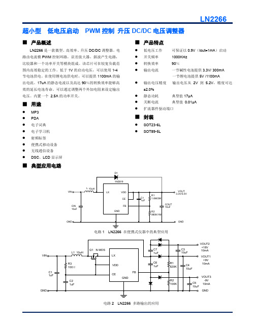
超小型 低电压启动 PWM 控制 升压DC/DC 电压调整器■ 产品概述LN2266是一款微型、高效率、升压DC/DC 调整器。
电路由电流模PWM 控制环路,误差放大器,斜波产生电路,比较器和一个功率开关等模块组成。
该芯片可在较宽负载范围内高效稳定的工作。
低于1V 的启动电压,可以使用1-4节电池供电。
在使用锂电池供电时,可以提供1100mA 的输出电流。
17uA 的静态电流以及高达90%的转换效率能够高效的延长电池寿命。
可以通过调整两个外加电阻来设定输出电压。
内置一个 2.5A 的功率开关。
■ 用途● MP3 ● PDA ● 电子词典 ● 电子学习机 ● 射频标签 ● 便携式移动设备 ● 无线通信设备 ●DSC 、LCD 显示屏■ 产品特点● 低电压工作 可保证以0.9V (Iout=1mA )启动 ● 开关频率 1000KHz ● 转换效率 90%●输出电流 一节碱性电池提供3.3V/ 300mA一节锂电池提供5V /1100mA●输出电压精度 输出电压从2V 到5.2V ,精度可达±2.0%● 静态功耗 典型值17μA ● 关断电流 典型值 0.01μA ● 扩流器件驱动端口■ 封装● SOT23-6L ●SOT89-5L■ 典型应用电路VOUT GND电路1 LN2266 在便携式仪器中的典型应用VOUT1+9V 10mAGNDVOUT2+18V 10mA VOUT3-9V 10mA电路2 LN2266 多路输出的应用■ 订购信息LN2266P ①②③④-⑤■ 引脚配置CE VDD FB SOT89-5L (TOP VIEW)12345CE NC GND FBSOT23-6L (TOP VIEW)LX123465VDDGNDLX■ 引脚分配■ 打印信息SOT23-6L, SOT89-5LSOT89-5L (TOP VIEW)12345SOT23-6L (TOP VIEW)123465① ② ③ ④① ② ③ ④① 表示产品系列② 代表产品的型号③代表基准电压的精度④代表产品生产批号数字0-9,A-Z,倒写数字0-9,A-Z,然后重复(G,I,J,O,Q,W除外)■功能框图VDDFBENGND ■绝对最大额定值■电学特性参数(VIN=1.5V,VDD=3.3V,负载电流=0,T a=25℃,除非另有指定)■特性曲线1.效率——输出电流2.供电电流——输入电压3.开关频率——Vdd端电压4.LX端波形——输出纹波5.瞬态响应6.输出电压——温度7.VIN VS 最大带载 (VOUT=5.0V)■封装信息 SOT23-6LSOT-89-5L。
电源管理 IC培训讲义PPT课件

1
概述:
• 任何电子设备都需要一个或几个输出电压恆定的直
流电源。通常的作法是将市电降压、整流、滤波、 稳压、输出一直流电压供装置使用。
• 在电源集成运用中,电源管理IC有独到之处,应用
最广泛。下面就简要介绍一下有关电源管理IC的一 些特征。
2
1.电源管理IC的分类:
集成稳压器的种类较多,可按以下几方面来分类
5
三端可调输出稳压IC(有正负输出电 压两类):
此处的三端是指电压输入端、电压输出端和电 压调整端。在电压调整端外接电位器后可对输出电 压进行调节,其主要特点是使用灵活。如正输出国 标通用的LM117系列、(LM217、LM317)、LM123 系列、LM140系列、LM138系列、LM150系列等;与 之对应的负输出也各有一个系列。这类稳压器的命 名方法无明显规律,封装也各异。
恒流源
基准 电压
误差 放大
Байду номын сангаас
地
调整管安全 工作区保护
短路保护 过热保护
~~
调整管
Rsc 输出
Ra
Rb
图一:78××系列稳压器电路框图
10
Ui
恒流源 基准电压
+
-
保护
R1
Uo
R2
图二: LM317系列稳压器电路框图
低通滤波
功率转换
整流滤波
N1
~220V/50Hz
高压DC
整流滤波
N2
低压DC
脉宽调制
控制电路
如正输出的78××系列,78后面的数字代表该 稳压IC输出的正电压数值,单位为V。例如7806既表 示稳压输出为+6V(相对于公共地端);7812表示 稳压输出为+12V等。有的型号在前面和后面还有一 个或几个英文字母,如W78××、AN78××、 L78××CV等等。前面的字母称“前缀”,一般是各 生产厂家的代号;后边的称“后缀”,用以表示输 出电压容差和封装外壳的类型等。如负输出的 79××系列,负输出与正输出比较,除输出电压为 负电压、引脚排列不同外,其命名方法、外型等均 与78××系列相同。
三种负电压电源设计
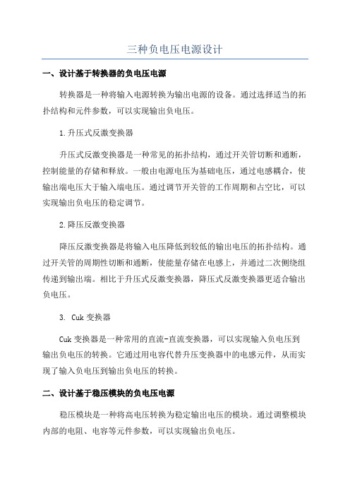
三种负电压电源设计一、设计基于转换器的负电压电源转换器是一种将输入电源转换为输出电源的设备。
通过选择适当的拓扑结构和元件参数,可以实现输出负电压。
1.升压式反激变换器升压式反激变换器是一种常见的拓扑结构,通过开关管切断和通断,控制能量的存储和释放。
一般由电源电压为基础电压,通过电感耦合,使输出端电压大于输入端电压。
通过调节开关管的工作周期和占空比,可以实现输出负电压的稳定调节。
2.降压反激变换器降压反激变换器是将输入电压降低到较低的输出电压的拓扑结构。
通过开关管的周期性切断和通断,使能量存储在电感上,并通过二次侧绕组传递到输出端。
相比于升压式反激变换器,降压式反激变换器更适合输出负电压。
3. Cuk变换器Cuk变换器是一种常用的直流-直流变换器,可以实现输入负电压到输出负电压的转换。
它通过用电容代替升压变换器中的电感元件,从而实现了输入负电压到输出负电压的转换。
二、设计基于稳压模块的负电压电源稳压模块是一种将高电压转换为稳定输出电压的模块。
通过调整模块内部的电阻、电容等元件参数,可以实现输出负电压。
1.线性稳压模块线性稳压模块在输入端通过电阻分压,将高电压转换为可调的中间电压。
然后通过稳压电路进一步降低中间电压,得到稳定的负电压输出。
线性稳压模块可以通过调整稳压器的电阻和电容来实现输出负电压的调节。
2.开关稳压模块开关稳压模块通过开关管的快速切断和通断,将输入电压转换为高频脉冲信号。
再通过滤波和稳压电路,将高频脉冲信号转换为稳定的负电压输出。
开关稳压模块具有高效率和较小的体积,适合用于负电压电源的设计。
三、设计基于反相放大器的负电压电源反相放大器是一种电路,可以将输入信号的幅度取反输出。
通过调节放大器的增益和输入信号,可以实现输出负电压。
1.可调增益反相放大器可调增益反相放大器可以通过调节放大器的增益来实现输出负电压的调节。
通过改变反馈电阻和输入电压,可以实现对负电压的放大和调节。
2.双电源反相放大器双电源反相放大器采用双电源供电,通过输入信号与放大器的放大增益相乘,得到负电压的输出。
1W超薄隔离型DCDC模块及其应用
1W超薄隔离型DC/DC模块及其应用豆豆网技术应用频道 2009年04月23日【字号:小中大】收藏本文关键字:电平逆变器电源适配器基站电池LabView为提高通信设备或装置在信号传输中的抗干扰能力,提高通信的可靠性及满足一些仪表、仪器在复杂环境中的测量精度、提高测量的可靠性,往往在其部分电路或器件上采用了输出稳压的隔离型电源模块供电。
这样不仅提高了电源的输出电压精度、减少纹波噪声电压;并且,由于采用了不共地的隔离电源,可以有效地抑制电磁干扰,消除接地环路的干扰,保护系统电路免受外部网络的影响。
在便携式仪器、仪表及通信装置中,采用超薄隔离型DC /DC模块,不仅占PCB面积小,并且可靠性高,是最佳的选择。
2008年,广州金升阳公司在DC/DC模块上有新的突破,开发出1W超薄隔离型DC/ DC模块系列。
该系列为定压输入,有非稳压输出及稳压输出两类。
本文介绍该系列中定压输入、稳压输出的1W超薄隔离型DC/DC模块,其型号为IF0505RN/RT-1W。
型号中前一个05的意思是输入电压,后一个05的意思是输出电压。
DC/DC电源模块IF0505RN/RT-1WIF0505RN/RT-1W是一种额定功率为1W、定压5V输入、单路5V稳压输出、隔离电压为3000VDC的DC/DC电源模块。
型号中有RN的为DIP封装,有RT的是贴片或SMD 封装。
该模块的主要特点:● 模块体积小,厚度超薄,仅4.5mm;● 输出电压精度高,可达±3%;● 隔离电压高达3000V,并且隔离电容小,仅为25pF;● 无须外部元器件;● 具有输出短路保护,短路排除后能自动恢复;● 输出纹波电压低,为传统的50%,其典型值为10mVp-p;● 温度稳定性高,温漂最大值为0.03%/℃;● 有DIP及SMD两种封装;● 工作温度范围为工业级,-40~+85℃;● 符合RoHS指令要求。
为提高输出电压精度及减小输出纹波、噪声电压,模块内还增加了一个低压差线稳压器(LDO),使性能进一步提高,其结构框图如图1所示。
负电压源 常用芯片
负电压源常用芯片以负电压源常用芯片为题,我们将介绍一些常见的负电压源芯片及其特点和应用。
一、LT1054芯片LT1054是一种高性能负电压转换器芯片,能够将正电压转换为负电压。
它具有高转换效率、高输出电流和宽输入电压范围的特点。
该芯片可以通过外部元件来调整输出电压和电流,非常适用于电源管理、传感器和无线通信等领域。
二、MAX660芯片MAX660是一种低功耗负电压转换器芯片,能够将正电压转换为负电压。
它具有低静态电流、高效率和小尺寸的特点。
该芯片广泛应用于便携式设备、医疗器械和工业自动化等领域。
三、TLE2426芯片TLE2426是一种精密电压源芯片,能够提供稳定的负电压输出。
它具有高精度、低温漂移和低噪声的特点。
该芯片常用于模拟电路、仪器仪表和音频设备等领域。
四、LT1055芯片LT1055是一种高精度负电压源芯片,能够提供稳定的负电压输出。
它具有低温漂移、低噪声和高输出电流的特点。
该芯片适用于精密测量、医疗设备和通信系统等领域。
五、LM2662芯片LM2662是一种高效率负电压转换器芯片,能够将正电压转换为负电压。
它具有高转换效率、低静态电流和小尺寸的特点。
该芯片常用于便携式设备、无线通信和电源管理等领域。
六、ADM8829芯片ADM8829是一种高精度负电压源芯片,能够提供稳定的负电压输出。
它具有低温漂移、低噪声和高输出电流的特点。
该芯片广泛应用于精密仪器、医疗设备和工业自动化等领域。
以上是一些常见的负电压源芯片,它们在不同的应用场景中发挥着重要作用。
通过选择合适的芯片,可以满足不同电压要求,并提供稳定、高效的负电压输出。
这些芯片的特点和优势使得它们在电子设备中得到广泛应用,推动了电子技术的发展和进步。
1.25V至20V可调直流稳压电源设计方案
直流稳定电源设计制作人:某某题目:直流稳定电源的设计一、任务:设计并制作交流变换为直流的稳定电源。
二、要求:1.基本要求(1)稳压电源在输入电压220V、50Hz、电压变化范围+15%~-20%条件下:a.输出电压可调范围为+9V~+12Vb.最大输出电流为1.5Ac.电压调整率≤0.2%(输入电压220V变化范围+15%~-20%下,空载到满载)d.负载调整率≤1%(最低输入电压下,满载)e.纹波电压(峰-峰值)≤5mV(最低输入电压下,满载)f.效率≥40%(输出电压9V、输入电压220V下,满载)g.具有过流及短路保护功能(2)稳流电源在输入电压固定为+12V的条件下:a.输出电流:4~20mA可调b.负载调整率≤1%(输入电压+12V、负载电阻由200Ω~300Ω变化时,输出电流为20mA时的相对变化率)(3)DC-DC变换器在输入电压为+9V~+12V条件下:a.输出电压为+100V,输出电流为10mAb.电压调整率≤1%(输入电压变化范围+9V~+12V)c.负载调整率≤1%(输入电压+12V下,空载到满载)d.纹波电压(峰-峰值)≤100mV (输入电压+9V下,满载)2.发挥部分(1)扩充功能a.排除短路故障后,自动恢复为正常状态b.过热保护c.防止开、关机时产生的“过冲”(2)提高稳压电源的技术指标a.提高电压调整率和负载调整率b.扩大输出电压调节范围和提高最大输出电流值(3)改善DC-DC变换器a.提高效率(在100V、100mA下)b.提高输出电压(4)用数字显示输出电压和输出电流.三,稳压电源的研究背景本电源在市场上很有应用前景,可以作为收音机或掌机的外接电源,也可以用作手机电池的充电器,功率高点的还作为小型电视或其他家用电器的电源。
直流稳压电源是电子技术常用的仪器之一,它现在广泛的应用在学校教学,科学研究等领域,是电子设计人员进行实验操作和科学研究必不可少的电子仪器。
在日常的电子电路中,供电电源常常要用到稳压直流电源。
K7805-1000 DC DC 中文技术资料
本 公 司 保 留 对 以 上 参 数 进 行 更 改 的 权 利,最 终 产 品 参 数 将 以 本 公 司 提 供 的 具 体 产 品 规 格 书 为 准 。
该版权归广州晶源电子有限公司所有
A1版 第1页 共3页
项目 纹 波+噪 声 短路输入功耗 短路保护 过热保护
vin最 小
v i n最 大
90
83
80
82
93
88
85
87
9.0~32
6.5
1000
94
90
IK7806-1000
7.0~25
-6.5
-400
88
90
12~32
9.0
1000
95
92
IK7809-1000
7.0~23
-9.0
-400
89
91
16~32
12.0
1000
96
94
IK7812-1000
7 . 0~2 0
25.4mm 25.4mm
+vin
GND
12.7mm
1 DC/DC 3 铝箔带
+ Vo
1μF 10μF
C1
2
陶
钽
负
瓷电
C2
电容
载
容
铝箔带
2、 启动输 出 波形及 负 载瞬态 响 应波形 的 测试电 路
2.54mm
外接示波器探头
+vin
GND
50.8mm
1 DC/DC 3 铝箔带
C1
2
C2
铝箔带
+ Vo
I K 7 8 * * - 1 0 0 0系 列
- 1、下载文档前请自行甄别文档内容的完整性,平台不提供额外的编辑、内容补充、找答案等附加服务。
- 2、"仅部分预览"的文档,不可在线预览部分如存在完整性等问题,可反馈申请退款(可完整预览的文档不适用该条件!)。
- 3、如文档侵犯您的权益,请联系客服反馈,我们会尽快为您处理(人工客服工作时间:9:00-18:30)。
TNC16XXXDW1A, -0.8V~-12V, NEGATIVE POWER MODULE特性∙ 1A 负电压输出 ∙ 小型封装∙ 输入电压范围:4.5V to 14V ∙ 输出电压范围:-0.8V to -8V ∙ 效率高达85% ∙ 可选工作温度区间 A 级: -20 o C to 70 o C B 级: -30 o C to 85 o C C 级: -40 o C to 125 o C ∙ 低压自动保护 ∙ 过载自动保护 ∙ 超温自动保护 ∙ 快速瞬态响应 ∙ 具有软启动功能 ∙ 轻载条件具有省电调节 ∙ 500kHz 开关频率∙ 下方允许高度1mm 元件放置应用∙ 复杂多电平系统 ∙ 数模/模数转换器 ∙ 信号调理 ∙ 运算放大器描述TNC16XXXDW 系列具有固定/可调电压输出和输出使能控制。
轻载省电调节功能特别适合低功耗应用。
由于具有极高的效率、极低的损耗,以及经过一定的热力学设计,TNC16XXXDW 系列能够提供1A 的输出带载能力。
高性价比、高稳定性以及微型体积帮助TNC16XXXDW 在科研设备、工业控制以及医疗领域成为明星产品。
输出过载保护和超温保护可以有效的对付电路故障,保护系统万全。
低压保护对于正在调试的系统或者干扰很大的系统具有很好的保护效果,可以避免昂贵的处理器受到电源系统冲击受损。
Realtimin 工程师为了减小模块体积和易于安装性上花费了大量心血。
模块使用双面贴装,最大化减小体积,并在此基础上设计了可供直插和贴装的引脚。
. 模块使用无铅工艺生产,满足RoHS 标准。
模块一览 (硬币大小:一角)Rev. A Information furnished by Realtime Instruments is believed to be accurate and reliable. However, no responsibility is assumed by Realtime Instruments for its use, nor for any infringements of patents or other rights of third parties that may result from its use. Specifications subject to changewithout notice. No license is granted by implication or otherwise under any patent or patent rights of Realtime Instruments. Trademarks and registered trademarks are the property of their respective owners.SPECIFICATIONS ELECTRICAL CHARACTERISTICSElectrical Characteristics(1) Lower than -8 V is safe, but set-point error may deteriorate 1%.(2) This control pin has an internal pull-up. Do not place an external pull-up on this pin. If it is left open-circuit, the module operates when input power is applied. If need to control, a small, low-leakage (<100 nA) MOSFET is recommended for control. For additional information, see the related application note.(3) At least one 47 µF electrolytic input capacitor is recommended for better operation. The electrolytic capacitor must be rated for a minimum of 500 mA rms of ripple current.(4) Output Capacitor must be MLCC type for its lower ESR characteristics.ENVIRONMENTAL AND ABSOLUTE MAXIMUM RATINGSEnvironmental and Absolute Maximum RatingsPIN CONFIGURATION AND FUNCTION DESCRIPTIONSTNC16XXXDWPin ConfigurationPin Function DescriptionsCoding DescriptionsOutput SelectionTYPICAL PERFORMANCE CHARACTERISTICSVI=12V, Unless otherwise noted, TA = 25℃Efficiency vs Load Current Output Variation vs Load CurrentOutput Variation vs Temperature Vout Ripple vs Load CurrentThermal Operating Area (Grade B)Operating FrequencyTERMINOLOGYLine RegulationLine regulation refers to the change in output voltage in response to a given change in input voltage and is expressed in percent per volt, ppm per volt, or µV per volt change in input voltage. The input voltage accounts for the variation of switching duty cycle.Load RegulationLoad regulation refers to the change in output voltage in response to a given change in load current and is expressed in µV per mA, ppm per mA, or ohms of dc output resistance. The load current accounts for the effects of self-heating.Overcurrent ThresholdFor protection against load faults, all modules incorporate output overcurrent protection. Applying a load that exceeds the regulator's overcurrent threshold causes the regulated output to shut down.Over-Temperature Protection (OTP)When the junction temperature increases above the rising threshold temperature, the module will enter the over-temperature protection state. The thermal sensor allows the converters to start a start-up process and regulate the output voltage again after the junction temperature cools by 45 o C. The OTP designed with a 45 o C hysteresis increases lifetime of the module.Transient ResponseThe transient response has been characterized using a load transient with a di/dt of 2.5 A/µs. The typical voltage deviation for this load transient is given with the minimum required value of output capacitance. As the di/dt of a transient is increased, the response of a converter’s regulation circuit ultimately depends on its output capacitor decoupling network. This is an inherent limitation with any dc/dc converter once the speed of the transient exceeds its bandwidth capability. This also means when a dc/dc converter has better transient response, the less output decoupling capacitor it need.Soft-Start Power UpThe TNC16XXXDW integrates soft-start circuits to ramp up the output voltage of the converter to the programmed regulation set point at a predictable slew rate. The slew rate of output voltage is internally controlled to limit the inrush current through the output capacitors during soft start process.Long-Term StabilityLong-term stability refers to the shift in the output voltage at 60o C after 1000 hours of operation in a 60o C environment. The ambient temperature is kept at 60o C to ensure that the temperature chamber does notswitch randomly between heating and cooling, which can cause instability over the 1000 hours’ measurement. APPLICATION INFORMATIONBasic connectionTypical Application CircuitInput CapacitorsTNC16XXXDW requires none minimum input capacitance. When V O> 3V, a 47μF electrolytic capacitor is recommended. Adding optionally one or more 10μF MLCC capacitor will always get better EMC results for the module.Output CapacitorTNC16XXXDW requires none minimum output capacitance due to its great transient characteristics. But adding optional one or more 22μF MLCC capacitor will improve ripple and transient performance. A combination of two 22μF MLCC capacitors is recommended.On/Off InhibitFor applications requiring output voltage on/off control, the TNC16XXXDW incorporates an EN control pin. The inhibit feature can be used wherever there is a requirement for the regulator to be turned off. The power modules function normally when the Inhibit pin is left open-circuit, providing a regulated output whenever a valid source voltage is connected to VI with respect to Vout. Open or 2V above GND= Normal operation, Vout = Off.This pin is a high voltage input, which has internal pull-up to VIN. It is hazardous to connect any low-level digital output driver directly to this pin, such as TTL logic or CMOS logic. Adopt a transistor to protect digital driver (usually IOs).Interfacing with IOUnder-Voltage ProtectionIn the process of operation, if a short circuit occurs, the output voltage will drop quickly. When load current is bigger than current limit threshold value, the output voltage will fall out of the required regulation range. The under-voltage protection circuit continually monitors the output voltage after soft-start is completed. If a load step is strong enough to pull the output voltage lower than the under voltage threshold, the under voltage threshold is 70% of the nominal output voltage, the internal UVP delay counter starts to count. After 16ms de-bounce time, the device turns off both high side and low-side MOSEFET with latched. T oggling enable pin to low, or recycling VIN, will clear the latch and bring the chip back to operation.Current Limit ProtectionThe TNC16XXXDW modules protect against load faults with a continuous current limit characteristic. Under a load fault condition the output current cannot exceed the current limit value. Attempting to draw current that exceeds the current limit value causes the output voltage to be progressively reduced. Current is continuously supplied to the fault until it is removed. Upon removal of the fault, the output voltage will promptly recover.Thermal ShutdownThermal shutdown protects the module’s internal circuitry against excessively high temperatures. A rise in temperature may be the result of a drop in airflow, a high ambient temperature, or a sustained current limit condition. If the junction temperature of the internal components exceeds T otp, the module will shut down. This reduces the output voltage to zero. The module will start up automatically, by initiating a soft-start power up when the sensed temperature decreases 40 °C below the thermal shutdown trip point.Power-Up CharacteristicsDuring start period, the TNC16XXXDW power modules produce a regulated output voltage whenever of a valid input voltage (minimum VIN) is applied from Vin. During the power-up period, internal soft-start circuitry slows the rate that the output voltage rises. This reduces the in-rush current drawn from the input source. The soft-start circuitry also introduces a short time delay into the power-up characteristic. The delay is from the point that a valid input source is recognized, to the initial rise of the output voltage.Soft StartTNC16XXXDW has an internal controlled timer for soft start function, which is fixedly set around 1ms.Adjusting VoutThere is an output adjustment resistor mounted on top side of TNC16XXXDW. The adjustment range of the TNC16XXXDW is -0.6V to -8 V. The adjustment method requires replacement of the resistor, RSET. The requirement of RSET is 0603(1608) package, 1/16W, 1% accuracy or higher, good thermal stability.For other output voltages, the value of the required resistor can either be calculated using the following formula, or simply selected from the range of values given in T able. The location of RSET is showing in nextchapter.R SET=11kΩ×0.6 Vo−0.6RSET for Standard Output VoltagesGrade Selection and Thermal ConsiderationRealtimin guarantee the correct behavior of the module over the full temperature range of corresponding grade. For highest grades, Realtimin not only employs better ICs and components, which has better temperature stabilization and better precision, but also adopts more producing procedure to ensure about 30% allowance. But when working under high ambient temperature (for example 85°C or higher, as shown in Thermal Operation Area), thermal protection function would limit MOSFET self-heating margin and eventually limit output current inevitably. Considering specific application environment, it might be necessary to take additional heat-sinking measures to improve the output capability when working under high ambient temperature, including:1.Deploy silicone grease to connect bottom side and mounting board to achieve better thermal coupling.2.Deploy silicone grease on top side to gain better thermal uniformity.3.Install heat radiator.e fan or other methods to strengthen air flow.OUTLINE DIMENSIONSTop View 0.036(0.9)0.126(3.2)0.055(1.4)0.126(3.2)SMT-PADNOTES:(1) All linear dimensions are in inches(mm)(2) This drawing is subject to change without notice.(3) 2 place decimals are ±0.030(±0.76mm).(4) 3 place decimals are ±0.010(±0.25mm).(5) Recommended keep out area for user components.(6) Power pin connection should utilize two or more vias to The interior power plane of 0.025(0.63) I.D. per input,ground and output pin (or the electrical equivalent).(7) Paste screen opening: 0.080(2.03) to 0.085(2.16). Paste screen thickness: 0.006(0.15).(8) Pad type: Solder mask defined.(9) All pins: Material – Copper Alloy plated by Nickel.ORDERING GUIDEOrdering Guide(1) XXX refers to Coding Description.(2) The marketing status values are defined as follows:ACTIVE: Product device recommended for new designs.LIFEBUY: Realtimin has announced that the device will be discontinued, and a lifetime-buy period is in effect.NRND: Not recommended for new designs. Devices is in production to support existing customers, using it in a new design is not recommended.PREVIEW: Device has been announced but is not in production. Samples may or may not be available.OBSOLETE: Realtimin has discontinued the production of the device.。