三层交换机划分3个vlan ,实现其互相通迅.
三层交换机实现VLAN间通信

三层交换机实现VLAN间通信前言在一个企业网络或数据中心网络中,往往需要将不同的用户组或业务分隔开,避免数据泄露和冲突。
为了实现这种隔离,我们可以使用 VLAN,即虚拟局域网。
通过将不同用户或业务分配到不同的 VLAN 中,可以隔离不同用户组或业务,从而提高网络的性能和安全性。
什么是三层交换机三层交换机是一种能够在网络中进行 IP 路由的交换机。
它可以在不同的 VLAN 之间进行路由,从而实现不同 VLAN 之间的通信。
三层交换机相较于普通的二层交换机,在交换机内部增加了路由模块,可以进行 IP 路由和子网划分等功能。
它在网络中起到了连接不同子网并提高网络吞吐量的作用。
1.高性能三层交换机支持硬件转发,可以实现数据包的快速转发,提高网络吞吐量。
因此,三层交换机适合用于网络中的主干区和汇聚区。
2.良好的扩展性三层交换机支持多种端口和模块,可以实现快速扩展和升级。
此外,三层交换机还可以支持多种协议,并且方便管理。
3.提高网络安全性由于三层交换机支持 VLAN 和 IP 路由功能,因此可以实现网络分割,提高网络的安全性。
同时,三层交换机还可以支持 QoS、ACL 等功能,进一步提高网络的安全性和可靠性。
1.路由方式路由方式可以实现不同 VLAN 之间的通信,因为路由器可以在不同的子网之间转发数据包。
在实际应用中,将三层交换机的某些接口划分为路由接口,并将其与路由器相连,从而实现 VLAN 间的通信。
使用路由方式实现 VLAN 间通信的示意图如下:2.子接口方式在前述的示意图中,三层交换机会将端口 VLANs 10,20,30 划分为三个子接口,这些子接口与路由器相连。
使用子接口方式时,需要注意使用 IEEE 802.1Q 标准来标识VLAN ID。
两种方式的比较:1.路由方式可以实现不同 VLAN 之间的通信,但需要较多的路由器接口和配置,操作不太方便。
而子接口方式可以将多个 VLAN 的通信实现在同一个物理接口上,方便管理和配置。
三层交换机划分3个vlan ,实现其互相通迅.

综合实验一台思科三层交换机划分3个vlan vlan 2:ip 192.168.1.1 255.255.255.0 192.168.1.254 网段vlan 3 :ip 192.168.2.1 255.255.255.0 192.168.2.254 vlan 4 ip 192.168.3.1 255.255.255.0192.168.3.254 各vlan 之间能互相通迅. 现在增加1台cisco路由想实现共享我们的PC0、PC1处在VLAN2中,PC2、PC3处在VLAN3中,Server0处在VLAN4中。
现在要使我们内网能够正常访问我们的Server0服务器,然后同时还要能够访问我们的ISP 外网的WWW服务器。
三层交换机的配置Switch#config tSwitch(config)#vlan 2 创建VLAN2Switch(config-vlan)#exiSwitch(config)#vlan 3 创建VLAN3Switch(config-vlan)#exiSwitch(config)#vlan 4 创建VLAN4Switch(config-vlan)#exitSwitch(config)#int fa0/2 将我们的fa0/2添加到VLAN2中Switch(config-if)#sw mo acSwitch(config-if)#sw ac vlan 2Switch(config-if)#exitSwitch(config)#int fa0/3将我们的FA0/3添加到VLAN3中Switch(config-if)#sw mo acSwitch(config-if)#sw ac vlan 3Switch(config-if)#exitSwitch(config)#int fa0/4 将我们的FA0/4添加到VLAN4中Switch(config-if)#sw mo acSwitch(config-if)#sw ac vlan 4Switch(config-if)#exitSwitch(config)#int vlan 2 给我们的VLAN2添加一个IP地址,用于不同网段之间互相访问Switch(config-if)#ip add 192.168.1.1 255.255.255.0Switch(config-if)#exitSwitch(config)#int vlan 3 给我们的VLAN3添加一个IP地址Switch(config-if)#ip add 192.168.2.1 255.255.255.0Switch(config-if)#exitSwitch(config)#int vlan 4给我们的VLAN4添加一个IP地址Switch(config-if)#ip add 192.168.3.1 255.255.255.0Switch(config-if)#no shutSwitch(config-if)#exit以下几行是用来给我们不同的VLAN内的主机自动分配我们的IP地址。
三层交换vlan间通信
三层交换机实现不同vlan间的通信我们知道不同的vlan之间要相互的通行必须要借用第三层,也就是网络层,可以路由器也可以是三层的交换机,在这里我主要是介绍用三层交换机来实现不同的vlan之间的的通信。
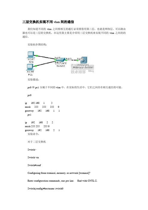
实验拓扑图结构:实验描述:pc0和pc1分属于不同的vlan中,在实际的生活中,它们之间存在相互通信的可能。
pc0ip 192 1681 2mask 255 255 255 0gataway 192 168 1 1pc1ip 192 168 2 2mask 255 255 255 0gataway 192 168 2 1实验命令:对于二层交换机Switch>Switch>enSwitch#confConfiguring from terminal, memory, or network [terminal]?Enter configuration commands, one per line. End with CNTL/Z.Switch(config)#hostname switch0switch0#vlan database% Warning: It is recommended to configure VLAN from config mode, as VLAN database mode is being deprecated. Please consult userdocumentation for configuring VTP/VLAN in config mode.switch0(vlan)#vlan 2 name 2VLAN 2 modified:Name: 2switch0(vlan)#vlan 3 name 3VLAN 3 added:Name: 3switch0(vlan)#exitAPPLY completed.Exiting....switch0#confConfiguring from terminal, memory, or network [terminal]?Enter configuration commands, one per line. End with CNTL/Z. switch0(config)#int f0/1switch0(config-if)#switchport mode accessswitch0(config-if)#switchport access vlan 2switch0(config-if)#exitswitch0(config)#int f0/3switch0(config-if)#switchport moswitch0(config-if)#switchport mode aswitch0(config-if)#switchport mode accessswitch0(config-if)#switchport access vlan 3switch0(config-if)#exitswitch0(config)#int f0/2switch0(config-if)#switchport mode trunkswitch0(config-if)#end%SYS-5-CONFIG_I: Configured from console by consoleswitch0#copy run starDestination filename [startup-config]?Building configuration...[OK]对于三层交换机Switch>enSwitch#Switch#confConfiguring from terminal, memory, or network [terminal]? Enter configuration commands, one per line. End with CNTL/Z. Switch(config)#ip routingSwitch(config)#interface f0/1Switch(config-if)#switchport mode trunkSwitch(config-if)#end%SYS-5-CONFIG_I: Configured from console by consoleSwitch#vlan database% Warning: It is recommended to configure VLAN from config mode,as VLAN database mode is being deprecated. Please consult userdocumentation for configuring VTP/VLAN in config mode.Switch(vlan)#vlan 2 name 2VLAN 2 added:Name: 2Switch(vlan)#vlan 3 name 3VLAN 3 added:Name: 3Switch(vlan)#exitAPPLY completed.Exiting....Switch#configure tSwitch#configure terminalEnter configuration commands, one per line. End with CNTL/Z.Switch(config)#intSwitch(config)#interface vlan 2%LINK-5-CHANGED: Interface Vlan2, changed state to up%LINEPROTO-5-UPDOWN: Line protocol on Interface Vlan2, changed state to upSwitch(c onfig-if)#ip addSwitch(config-if)#ip address 192.168.1.1 255.255.255.0Switch(config-if)#no shSwitch(config-if)#no shutdownSwitch(config-if)#exitSwitch(config)#int vlan 3%LINK-5-CHANGED: Interface Vlan3, changed state to up%LINEPROTO-5-UPDOWN: Line protocol on Interface Vlan3, changed state to upSwitch(c onfig-if)#ip add 192.168.2.1 255.255.255.0Switch(config-if)#no shSwitch(config-if)#end%SYS-5-CONFIG_I: Configured from console by consoleSwitch#copy run starDestination filename [startup-config]?Building configuration...[OK]Switch#show ip routeCodes: C - connected, S - static, I - IGRP, R - RIP, M - mobile, B - BGPD - EIGRP, EX - EIGRP external, O - OSPF, IA - OSPF inter areaN1 - OSPF NSSA external type 1, N2 - OSPF NSSA external type 2E1 - OSPF external type 1, E2 - OSPF external type 2, E - EGPi - IS-IS, L1 - IS-IS level-1, L2 - IS-IS level-2, ia - IS-IS inter area* - candidate default, U - per-user static route, o - ODRP - periodic downloaded static routeGateway of last resort is not setC 192.168.1.0/24 is directly connected, Vlan2C 192.168.2.0/24 is directly connected, Vlan3测试Pinging 192.168.2.2with 32 bytes of data:Reply from 192.168.2.1: bytes=32 time=63ms TTL=255Reply from 192.168.2.1: bytes=32 time=63ms TTL=255Reply from 192.168.2.1: bytes=32 time=63ms TTL=255Reply from 192.168.2.1: bytes=32 time=62ms TTL=255Ping statistics for 192.168.2.1:Packets: Sent = 4, Received = 4, Lost = 0 (0% loss),Approximate round trip times in milli-seconds:Minimum = 62ms, Maximum = 63ms, Average = 62ms实验成功。
三层交换机实现不同VLAN之间的通信
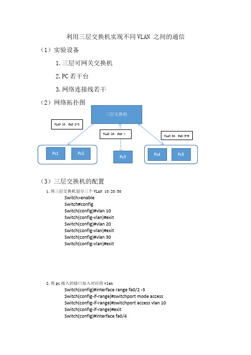
利用三层交换机实现不同VLAN 之间的通信(1)实验设备1.三层可网关交换机2.PC若干台3.网络连接线若干(3)三层交换机的配置1.将三层交换机划分三个VLAN 10/20/30Switch>enableSwitch#configSwitch(config)#vlan 10Switch(config-vlan)#exitSwitch(config)#vlan 20Switch(config-vlan)#exitSwitch(config)#vlan 30Switch(config-vlan)#exit2.将pc接入的接口加入对应的vlanSwitch(config)#interface range fa0/2 -3Switch(config-if-range)#switchport mode accessSwitch(config-if-range)#switchport access vlan 10Switch(config-if-range)#exitSwitch(config)#interface fa0/4Switch(config-if)#switchport mode accessSwitch(config-if)#switchport access vlan 20Switch(config-if)#exitSwitch(config)#interface range fa0/5 -6Switch(config-if-range)#switchport mode accessSwitch(config-if-range)#switchport access vlan 30Switch(config-if-range)#endSwitch#%SYS-5-CONFIG_I: Configured from console by consoleSwitch#writeBuilding configuration...[OK]3.给三个VLAN设置IP地址,该地址作为pc的默认网关Switch(config)#interface vlan 10Switch(config-if)#ip address 192.168.10.254 255.255.255.0Switch(config-if)#exitSwitch(config)#interface vlan 20Switch(config-if)#ip address 192.168.20.254 255.255.255.0Switch(config-if)#exitSwitch(config)#interface vlan 30Switch(config-if)#ip address 192.168.30.254 255.255.255.0Switch(config-if)#exitSwitch(config)#exitSwitch#writeBuilding configuration...[OK]Switch#Switch#4.开启路由器的路由功能 IP routingSwitch(config)#ip routingSwitch(config)#Switch(config)#endSwitch#%SYS-5-CONFIG_I: Configured from console by consoleSwitch#。
三层交换机实现VLAN间通信

三层交换机实现VLAN间通信三层交换机可以实现VLAN间通信,即不同VLAN之间的主机可以互相通信。
下面将从三层交换机的原理、实现方法以及优缺点等方面进行详细介绍。
三层交换机是在二层交换机的基础上增加了三层功能,即支持IP协议栈的路由功能。
它可以实现不同VLAN间的通信,通过将不同VLAN的信号进行路由处理,使得主机在不同VLAN间可以进行通信,实现了虚拟局域网之间的互通。
实现VLAN间通信的方法有两种:静态路由和动态路由。
静态路由是通过手动配置交换机的路由表来实现VLAN间通信。
管理员需要手动配置交换机上每个子网的网关地址,并设置路由表,指明从哪个接口出去到达目标VLAN。
这种方法配置简单,但不适合规模较大的网络,因为需要手动维护路由表。
动态路由是通过使用动态路由协议,如OSPF、RIPv2等,来自动学习和更新路由表,实现自动的VLAN间通信。
这种方法适合规模较大的网络,因为可以自动更新路由表,减少管理员的配置工作。
1. 提高网络性能:通过实现VLAN间的通信,可以减少广播域的范围,减少广播报文的传输,提高网络性能。
2. 增强网络安全性:通过划分不同的VLAN,可以实现不同VLAN的隔离,阻止不同VLAN间的流量传播,增强网络的安全性。
3. 提供灵活性:通过使用三层交换机的路由功能,可以将不同的VLAN划分到不同的子网中,提供更灵活的网络管理和更好的资源利用。
1. 成本较高:相比于二层交换机,三层交换机的成本较高,对于小型网络来说可能不划算。
2. 复杂性:三层交换机的配置相对复杂,需要管理员具备一定的网络知识和技能才能正确配置。
三层交换机可以实现VLAN间通信,通过路由功能将不同VLAN的信号进行路由处理,从而实现虚拟局域网之间的互通。
不同的实现方法有静态路由和动态路由,优点包括提高网络性能、增强网络安全性和提供灵活性,缺点包括成本较高和配置复杂。
3层交换机实训VLAN之间通信

实训项目:利用三层交换机实现VLAN间通信实训目的:熟悉和掌握VLAN的划分和配置方法;能够配置三层交换机实现VLAN之间的通信;能够配置三层交换机启用路由功能。
任务描述:公司的三个部门已经分别属于三个不同的VLAN,现在要求不同的VLAN之间要进行数据共享,能够实现资源共享。
为了解决不同虚拟局域网之间的通信问题,需要启用一台3层交换机来实现。
实训环境:实训拓扑图在三层交换机上建立三个VLAN:VLAN 10(1-8)分配给财务部、VLAN 20(9-18)分配给销售部,VLAN 30(19-24)分配给办公室,为了实现三个部门的主机能够互相访问,三层交换机上开启路由功能,并在VLAN 1O中设置IP地址为192.168.10.1,也就是VLAN 10的网关;在VLAN 2O中设置IP地址为192.168.20.1,也就是VLAN 20的网关; 在VLAN 3O中设置IP地址为192.168.30.1,也就是VLAN 30的网关。
实训步骤:1. 硬件连接,按图中所示的拓扑结构连接;2. 配置PC10、PC11、 PC20、PC21、PC30、PC31的IP地址和子网掩码;3.分别测试PC10、PC11、 PC20、PC21、PC30、PC31的连通性;4.配置交换机1)创建VLAN 10 、VLAN 20 、VLAN 30(略);2)将端口分配到VLAN (略);3)配置三层交换机端口的路由功能;Switch3560#conf tSwitch3560(config)#ip routingSwitch3560(config)#int vlan 10Switch3560(config-if)#ip address 192.168.10.1 255.255.255.0 Switch3560(config-if)#no shutdownSwitch3560(config-if)#exitSwitch3560(config)#int vlan 20Switch3560(config-if)#ip address 192.168.20.1 255.255.255.0Switch3560(config-if)#no shutdownSwitch3560(config-if)#exitSwitch3560(config)#int vlan 30Switch3560(config-if)#ip address 192.168.30.1 255.255.255.0Switch3560(config-if)#no shutdownSwitch3560(config-if)#exit5.分别测试PC10、PC11、 PC20、PC21、PC30、PC31的连通性;小结:1.VLAN之间的通信等同于不同广播域之间的通信,必须借助三层设备。
通过三层交换机实现不同VLAN间互相通信

通过三层交换机实现不同VLAN间互相通信虚拟局域网(VLAN)是一种将网络设备划分为逻辑上相互隔离的网络的方法。
通过使用三层交换机,可以实现不同VLAN之间的互相通信。
三层交换机是一种在第三层网络层上工作的网络设备,它可以识别和转发IP数据包。
实现不同VLAN之间互相通信的方法是通过三层交换机上的路由功能。
三层交换机可以连接多个VLAN,并通过路由表来决定将数据包转发到哪个VLAN。
以下是实现这种通信的步骤:1.VLAN划分:首先需要将网络设备划分为不同的VLAN。
每个VLAN可以看作是一个逻辑上的独立网络,在这个网络中的设备可以互相通信。
2.配置三层交换机:将三层交换机连接到各个VLAN,并配置每个VLAN的IP地址。
每个VLAN应该有一个唯一的IP地址段,以便在进行路由转发时能够区分不同的VLAN。
3.配置路由表:在三层交换机上配置路由表,以便能够将数据包从一个VLAN路由到另一个VLAN。
路由表通常包含有关目的IP地址和相关出口接口的信息。
4.配置静态路由:如果有多个三层交换机连接了不同的VLAN,而且需要在它们之间进行路由转发,那么需要配置静态路由。
静态路由是在网络管理员手动配置的路由表条目,用于指定将数据包发送到哪个接口。
5.配置默认路由:在三层交换机上配置默认路由,以便在无法找到与目标IP地址匹配的路由表项时,将数据包发送到默认的出口接口。
通过上述步骤,不同VLAN之间的通信就可以成功实现。
当设备位于不同的VLAN时,它们可以使用其相应的VLANIP地址进行通信。
三层交换机将根据路由表中的信息决定将数据包转发到哪个VLAN,并在目标VLAN 中将数据包交付给目标设备。
总结起来,通过三层交换机实现不同VLAN间互相通信的步骤包括VLAN划分、配置三层交换机、配置路由表、配置静态路由和配置默认路由。
通过这种方法,可以实现不同VLAN之间的隔离和互相通信,增强网络的灵活性和安全性。
华为交换机VLAN间的三层通信
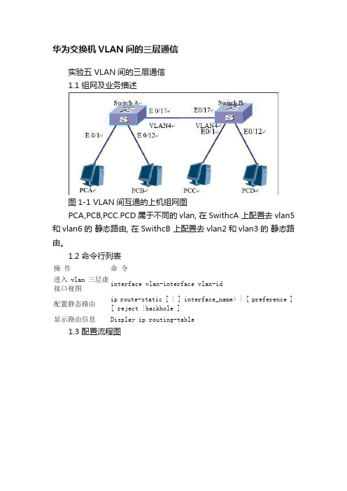
华为交换机VLAN间的三层通信实验五 VLAN间的三层通信1.1 组网及业务描述图1-1 VLAN间互通的上机组网图PCA,PCB,PCC.PCD属于不同的vlan, 在SwithcA 上配置去vlan5和vlan6的静态路由, 在SwithcB 上配置去vlan2和vlan3的静态路由。
1.2 命令行列表操作命令进入vlan三层虚接口视图interface vlan-interface vlan-id配置静态路由ip route-static [ | ] interface_name> | [ preference ] [ reject |backhole ]显示路由信息Display ip routing-table1.3 配置流程图1.4 配置步骤1、配置各PC的IP地址及网关地址首先按照上图连接各实验设备,然后配置PCA IP地址为10.1.2.2/24,网关地址为10.1.2.1/24;PCB IP地址为10.1.3.2/24,网关地址为10.1.3.1/24;PCC IP地址为10.1.5.2/24,网关地址为10.1.5.1/24,PCD IP地址为10.1.6.2/24,网关地址为10.1.6.1/24。
2、配置VLAN及所属端口在交换机A上创建三个VLAN:VLAN 2、VLAN 3和VLAN 4,配置端口Ethernet 0/1 属于VLAN 2;端口Ethernet0/12 属于 VLAN 3;端口Ethernet0/17 属于VLAN 4。
在交换机B上创建三个VLAN:VLAN 5、VLAN 6和VLAN 4,配置端口Ethernet 0/1 属于VLAN 5,端口Ethernet0/12 属于VLAN 6,端口Ethernet0/17 属于VLAN 4。
3、创建三层接口,并配置IP地址在Switch A上创建三个三层虚接口,并配置IP地址VLAN2的IP地址是10.1.2.1,掩码是255.255.255.0 VLAN3的IP地址是10.1.3.1,掩码是255.255.255.0 VLAN4的IP地址是10.1.4.1,掩码是255.255.255.0 在Switch B上创建三个三层虚接口,并配置IP地址VLAN5的IP地址是10.1.5.1,掩码是255.255.255.0 VLAN6的IP地址是10.1.6.1,掩码是255.255.255.0 VLAN4的IP地址是10.1.4.2,掩码是255.255.255.0 在交换机上配置非直连网段静态路由在Switch A上配置两静态路由:ip route-static 10.1.5.0 255.255.255.0 10.1.4.2ip route-static 10.1.6.0 255.255.255.0 10.1.4.2在Switch B上配置两静态路由:ip route-static 10.1.2.0 255.255.255.0 10.1.4.1ip route-static 10.1.3.0 255.255.255.0 10.1.4.1 1.5 配置参考1.5.1 配置VLAN及所属端口1. 配置RTA[Switch A]vlan 2[Switch A-vlan2]port Ethernet 0/1[Switch A]vlan 3[Switch A-vlan3]port Ethernet 0/12[Switch A]vlan 4[Switch A-vlan4]port Ethernet 0/172. 配置RTB[Switch B]vlan 5[Switch B-vlan5]port Ethernet 0/1[Switch B]vlan 6[Switch B-vlan6]port Ethernet 0/12[Switch B]vlan 4[Switch B-vlan4]port Ethernet 0/171.5.2 创建三层接口1. 配置RTA[Switch A]interface Vlan-interface 2[Switch A-Vlan-interface2]ip address 10.1.2.1 255.255.255.0 [Switch A]interface vlan-interface 3[Switch A-Vlan-interface3]ip address 10.1.3.1 255.255.255.0 [Switch A]interface vlan-interface 4[Switch A-Vlan-interface4]ip address 10.1.4.1 255.255.255.0 2. 配置RTB[Switch B]interface Vlan-interface 5[Switch B-Vlan-interface5]ip address 10.1.5.1 255.255.255.0 [Switch B]interface vlan-interface 6[Switch B-Vlan-interface6]ip address 10.1.6.1 255.255.255.0 [Switch B]interface vlan-interface 4[Switch B-Vlan-interface4]ip address 10.1.4.2 255.255.255.0 1.5.3 配置静态路由1. 配置RTA[Switch A]ip route-static 10.1.5.0 255.255.255.0 10.1.4.2 [Switch A]ip route-static 10.1.6.0 255.255.255.0 10.1.4.2 2. 配置RTB[Switch B]ip route-static 10.1.2.0 255.255.255.0 10.1.4.1 [Switch B]ip route-static 10.1.3.0 255.255.255.0 10.1.4.1。
- 1、下载文档前请自行甄别文档内容的完整性,平台不提供额外的编辑、内容补充、找答案等附加服务。
- 2、"仅部分预览"的文档,不可在线预览部分如存在完整性等问题,可反馈申请退款(可完整预览的文档不适用该条件!)。
- 3、如文档侵犯您的权益,请联系客服反馈,我们会尽快为您处理(人工客服工作时间:9:00-18:30)。
综合实验
一台思科三层交换机划分3个vlanvlan2:ip网段vlan3:ipvlan4ip各vlan之间能互相通迅.现在增加1台cisco路由想实现共享
我们的PC0、PC1处在VLAN2中,PC2、PC3处在VLAN3中,Server0处在VLAN4中。
现在要使我们内网能够正常访问我们的Server0服务器,然后同时还要能够访问我们的ISP外网的WWW服务器。
三层交换机的配置
Switch#configt
Switch(config)#vlan2创建VLAN2
Switch(config-vlan)#exi
Switch(config)#vlan3创建VLAN3
Switch(config-vlan)#exi
Switch(config)#vlan4创建VLAN4
Switch(config-vlan)#exit
Switch(config)#intfa0/2将我们的fa0/2添加到VLAN2中
Switch(config-if)#swmoac
Switch(config-if)#swacvlan2
Switch(config-if)#exit
Switch(config)#intfa0/3将我们的FA0/3添加到VLAN3中
Switch(config-if)#swmoac
Switch(config-if)#swacvlan3
Switch(config-if)#exit
Switch(config)#intfa0/4将我们的FA0/4添加到VLAN4中
Switch(config-if)#swmoac
Switch(config-if)#swacvlan4
Switch(config-if)#exit
Switch(config)#intvlan2给我们的VLAN2添加一个IP地址,用于不同网段之间互相访问
Switch(config-if)#ipadd
Switch(config-if)#exit
Switch(config)#intvlan3给我们的VLAN3添加一个IP地址
Switch(config-if)#ipadd
Switch(config-if)#exit
Switch(config)#intvlan4给我们的VLAN4添加一个IP地址
Switch(config-if)#ipadd
Switch(config-if)#noshut
Switch(config-if)#exit
以下几行是用来给我们不同的VLAN内的主机自动分配我们的IP地址。
Switch(config)#ipdhcppoolVLAN2
Switch(dhcp-config)#network
Switch(dhcp-config)#default-router
Switch(dhcp-config)#exit
Switch(config)#ipdhcppoolVLAN3
Switch(dhcp-config)#network192.168.2.0
Switch(dhcp-config)#default-router
Switch(dhcp-config)#exit
Switch(config)#
Switch(config)#intfa0/24
Switch(config-if)#noswitchport关闭二层端口,这样就可以配置IP地址了
Switch(config-if)#ipadd它现在是一个三层端口,它可以配置IP地址
Switch(config-if)#noshut
Switch(config-if)#exit
Switch(config)#iprouting开启路由功能,如果不开启路由功能就不能使用路由协议
Switch(config)#routerrip我们这里运行一个rip协议
Switch(config-router)#ver2
Switch(config-router)#noau
Switch(config-router)#net
Switch(config-router)#net
Switch(config-router)#net
Switch(config-router)#net
Switch(config-router)#exit
Switch(config)#
路由器的配置
fa0/0
Router(config-router)#default-informationoriginate它的作用是给我们三层路由器分配一条默认路由出去!
Router(config-router)#exit
Router(config)#
Router(config)#access-list1permit0.0.0.255
Router(config)#access-list1permit
Router(config)#access-list1permit
Router(config)#ipnatinsidesourcelist1interfaces0/0overload Router(config)#ints0/0
Router(config-if)#ipnatout side
Router(config-if)#exit
Router(config)#intfa0/0
Router(config-if)#ipnatinside
Router(config-if)#end
Router(config)#iproutes0/0
ISP端路由器的配置
Router#conft
Router(config)#hostISP
ISP(config)#ints0/0
ISP(config-if)#ipadd
ISP(config-if)#noshut
ISP(config-if)#clockrate64000
ISP(config-if)#exit
ISP(config)#intfa0/0
ISP(config-if)#ipadd
ISP(config-if)#noshut
ISP(config-if)#exit
ISP(config)#。