康明斯电喷发动机故障代码
康明斯ISBE故障代码(new)
1
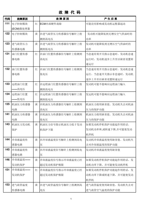
代码
故障原因
154 进气歧管温度
传感器电路
155 进气歧管压力
/温度传感器—
可能对性能没有影响或性能严重下降
黄 在电子控制模块(ECM)在进气歧管压 连接到这个+5-VDC电源上的传感器使用
力温度传感器\OEM压力传感器\冷却 缺省值,而且可能按缺省怠速运行,由于
液液位传感器以太远程油门提供电源 按照没有增压的状态供油,发动机功率将
的导线上检测到低电压
会降低,并且会失去这些传感器对发动机
代码
故障原因
111 电子控制模块
(ECM)微处理器
122 电子控制模块
123 进气歧管压力 传感器电路
131 油门位置传感 器电路
132 油门位置传感 器电路
133 远程油门位置 ——高电压
134 远程油门位置 ——低电压
135 机油压力传感器 电路
141 机油压力传感器 电路
143 机油压力发动机 保护
黄 当其它发动机参数批示进气歧管压力 发动机将降低到无增压空气供油时的功率 应当较低时,进气歧管压力信号却显示 进气歧管压力过高
黄 上一次钥匙接通时电子控制模块(ECM 对性能没有影响.故障代码图表\里程信息 收集的所有数据在上一次钥匙断开后 数据以及保养监视器数据可能不准确 未储存到永久性存储器中.
红 在油门位置传感器信号触针上检测到 高电压
红 在油门位置传感器信号触针上检测到 低电压
红 在远程油门位置传感器信号触针上检 测到高电压
康明斯柴油发动机QSK19、QSK23、QSK45、QSK60 和 QSK78维修保养故障代码

康明斯柴油发动机QSK19、QSK23、QSK45、QSK60 和QSK78 维修保养故障代码Cummings diesel engine QSK19, QSK23, QSK45, QSK60and QSK78repair maintenance fault code第TF 节—故障代码诊断及排除Section TF - fault code diagnosis and elimination◆(ch19-fc111) 电子控制模块(ECM)微处理器The electronic control module ( ch19-fc111) ( ECM ) microprocessor◆(ch19-fc112) 正时供油流量不匹配The ( ch19-fc112) timing injection flow mismatch◆(ch19-fc113) 正时执行器电路The ( ch19-fc113) timing actuator circuit◆(ch19-fc115) 发动机速度传感器电路The ( ch19-fc115) engine speed sensor circuit◆(ch19-fc116) 正时压力传感器电路The ( ch19-fc116) when the pressure sensor circuit◆(ch19-fc117) 正时压力传感器电路The ( ch19-fc117) when the pressure sensor circuit◆(ch19-fc118) 燃油泵压力传感器电路The ( ch19-fc118) fuel pump pressure sensor circuit◆(ch19-fc119) 燃油泵压力传感器电路The ( ch19-fc119) fuel pump pressure sensor circuit◆(ch19-fc121) 发动机速度传感器电路The ( ch19-fc121) engine speed sensor circuit◆(ch19-fc122) 进气歧管压力传感器电路( ch19-fc122) the intake manifold pressure sensor circuit◆(ch19-fc123) 进气歧管压力传感器电路( ch19-fc123) the intake manifold pressure sensor circuit◆(ch19-fc131) 油门位置传感器:CELECT ™ 型油门踏板The throttle position sensor ( ch19-fc131): CELECT ™type accelerator pedal ◆(ch19-fc132) 油门位置传感器:CELECT ™ 型油门踏板The throttle position sensor ( ch19-fc132): CELECT ™type accele rator pedal ◆(ch19-fc133) 远程油门位置传感器:CELECT ™ 型油门踏板The ( ch19-fc133) remote throttle position sensor: CELECT ™type accelerator pedal◆(ch19-fc134) 远程油门位置传感器:CELECT ™ 型油门踏板The ( ch19-fc134) remote throttle position sensor: CELECT ™type accelerator pedal◆(ch19-fc135) 机油压力传感器电路( ch19-fc135) the oil pressure sensor circuit◆(ch19-fc141) 机油压力传感器电路( ch19-fc141) the oil pressure sensor circuit◆(ch19-fc143) 机油压力—发动机保护The ( ch19-fc143) - engine oil pressure protection◆(ch19-fc144) 冷却液温度传感器电路( ch19-fc144) the coolant temperature sensor circuit◆(ch19-fc145) 冷却液温度传感器电路( ch19-fc145) the coolant temperature sensor circuit◆(ch19-fc147) 油门频率电路The ( ch19-fc147) accelerator frequency circuit◆(ch19-fc148) 油门频率电路The ( ch19-fc148) accelerator frequency circuit◆(ch19-fc151) 冷却液温度—发动机保护The ( ch19-fc151) - engine coolant temperature protection◆(ch19-fc153) 进气歧管温度传感器电路( ch19-fc153) the intake manifold temperature sensor circuit◆(ch19-fc154) 进气歧管温度传感器电路( ch19-fc154) the intake manifold temperature sensor circuit◆(ch19-fc155) 进气歧管温度传感器- 发动机保护( ch19-fc155) the intake manifold temperature sensor - engine protection ◆(ch19-fc219) 补充油箱机油油位低故障The (ch19-fc219) supplementary tank oil level low fault◆(ch19-fc221) 大气压力传感器电路The ( ch19-fc221) atmospheric pressure sensor circuit◆(ch19-fc222) 大气压力传感器电路The ( ch19-fc222) atmospheric pressure sensor circuit◆(ch19-fc223) 燃烧电磁阀电路The ( ch19-fc223) combustion electromagnetic valve circuit◆(ch19-fc225) 补充电磁阀电路( ch19-fc225) supplement of electromagnetic valve circuit◆(ch19-fc231) 冷却液压力传感器电路( ch19-fc231) the coolant pressure sensor circuit◆(ch19-fc232) 冷却液压力传感器电路( ch19-fc232) the coolant pressure sensor circuit◆(ch19-fc233) 冷却液压力- 发动机保护The ( ch19-fc233) - engine cooling fluid pressure protection ◆(ch19-fc234) 发动机超速The ( ch19-fc234) engine overspeed◆(ch19-fc235) 发动机冷却液液位—发动机保护The ( ch19-fc235) engine coolant level - engine protection◆(ch19-fc237) 多机同步( ch19-fc237) of multi machine synchronous◆(ch19-fc252) 机油油位传感器电路( ch19-fc252) the oil level sensor circuit◆(ch19-fc253) 机油油位- 发动机保护The ( ch19-fc253) - engine oil level protection◆(ch19-fc254) 燃油切断电磁阀电源电路The ( ch19-fc254) fuel cut solenoid valve power supply circuit ◆(ch19-fc259) 燃油切断阀卡在开启位置( ch19-fc259) the fuel cut valve stuck in the open position◆(ch19-fc261) 燃油温度—发动机保护( ch19-fc261) of oil temperature, engine protection◆(ch19-fc263) 燃油温度传感器电路The ( ch19-fc263) fuel temperature sensor circuit◆(ch19-fc265) 燃油温度传感器电路The ( ch19-fc265) fuel temperature sensor circuit◆(ch19-fc292) OEM 温度- 发动机保护The (ch19-fc292) OEM temperature - engine protection◆(ch19-fc293) OEM 温度传感器电路The ( ch19-fc293) OEM temperature sensor circuit◆(ch19-fc294) OEM 温度传感器电路The ( ch19-fc294) OEM temperature sensor circuit◆(ch19-fc296) OEM 压力—发动机保护The (ch19-fc296) OEM pressure, engine protection◆(ch19-fc297) OEM 压力传感器电路The ( ch19-fc297) OEM pressure sensor circuit◆(ch19-fc298) OEM 压力传感器电路The ( ch19-fc298) OEM pressure sensor circuit◆(ch19-fc299) 非钥匙开关热停机The ( ch19-fc299) - a key switch thermal shutdown◆(ch19-fc316) 燃油泵执行器电路The ( ch19-fc316) fuel pump actuator circuit◆(ch19-fc318) 燃油泵供油流量不匹配The ( ch19-fc318) fuel pump flow mismatch◆(ch19-fc343) 电子控制模块(ECM)内部通信错误The electronic control module ( ch19-fc343) ( ECM ) internal communication error◆(ch19-fc346) 电子控制模块(ECM)断电错误The electronic control module ( ch19-fc346) ( ECM ) power error◆(ch19-fc349) 油门频率电路The ( ch19-fc349) accelerator frequency circuit◆(ch19-fc384) 乙醚喷射电路The ( ch19-fc384) ether injection circuit◆(ch19-fc415) 机油压力—发动机保护The ( ch19-fc415) - engine oil pressure protection◆(ch19-fc422) 冷却液液位传感器电路( ch19-fc422) the coolant level sensor circuit◆(ch19-fc423) 正时压力传感器在正常工作范围内的误差The ( ch19-fc423) when the pressure sensor in the normal working range of the error第TS 节—症状的故障诊断及排除Section TS - symptoms for fault diagnosis and elimination◆(t00-001) 故障诊断及排除的步骤和技巧The ( t00-001) fault diagnosis and troubleshooting steps and tips◆(t00-002) 症状故障诊断表The ( t00-002) symptom fault diagnosis chart◆(t033) 发动机加速性能或响应差The ( T033) engine acceleration or response difference◆(t041) 发动机减速缓慢The ( t041) engine speed is slow◆(t043) 发动机起动困难或不能起动(排气冒烟)The ( T043) engine starting difficulty or cannot start ( exhaust smoke )◆(t044) 发动机起动困难或不能起动(没有排气冒烟)The ( t044) engine starting difficulty or cannot start ( no exhaust smoke )◆(t062) 发动机运转粗暴或缺火( t062) the engine running roughly or misfire◆(t064) 减速时发动机意外停机或熄火The (t064) deceleration when the unexpected shutdown or flameout of engine ◆(t066) 发动机低怠速或高怠速时悠车The ( t066) low engine idle speed or high idling you car◆(t067) 发动机带负荷时或在工作范围内悠车( T067) the engine load or within the scope of work in you car◆(t072) 发动机能够起动但不能保持运转( t072) the engine can start but can't keep running◆(t080) 发动机达不到额定转速(RPM)The ( t080) engine did not reach the rated speed ( RPM )◆(t081) 发动机不能停机The ( t081) engine cannot stop◆(t083) 故障代码报警指示灯一直亮(无明显的原因)The ( t083) fault code alarm indicator light ( for no apparent reason )◆(t084) 故障代码报警指示灯不亮The ( t084) fault code alarm indicator light is not bright◆(t087) 燃油消耗过大The (t087) fuel consumption is too large◆(t102-25) 机油补充油箱内机油消耗过大The (t102-25) oil supplement oil tank oil consumption is too large◆(t102-5) 机油补充油箱内机油消耗不足The (t102-5) oil tank oil consumption insufficient supplement◆(t103-25) 使用正确量的补偿机油时发动机机油油位高于技术规范The (t103-25) using the correct amount of compensation oil engine oil level is higher than the technical specification◆(t103-5) 使用正确量的补偿机油时发动机机油油位低于技术规范The (t103-5) using the correct amount of compensation oil engine oil level is lower than the technical specification◆(t116) 大量冒黑烟The large number of black smoke ( t116)◆(t118) 大量冒白烟The large number of white smoke ( T118)。
康明斯故障代码
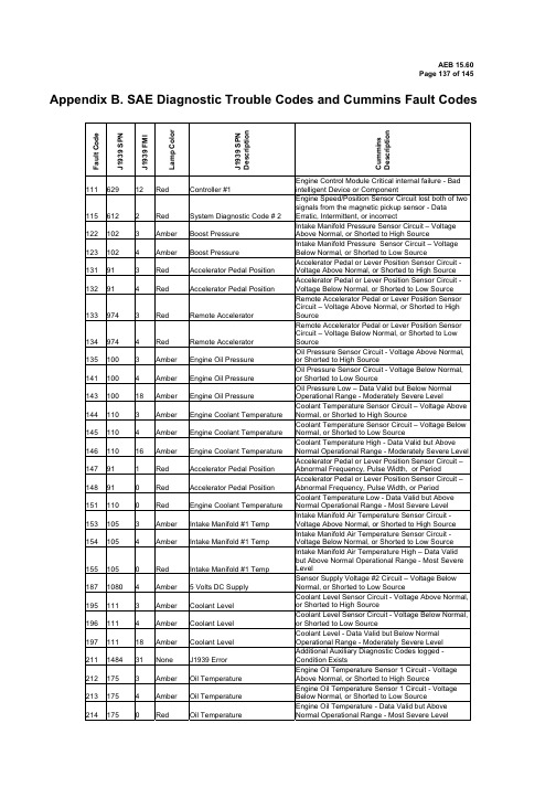
Appendix B. SAE Diagnostic Trouble Codes and Cummins Fault CodesF a u l t C o d eJ 1939 S P NJ 1939 F M IL a m p C o l o rJ 1939 S P N D e s c r i p t i o nC u m m i n sD e s c r i p t i o n111 629 12 Red Controller #1Engine Control Module Critical internal failure - Bad intelligent Device or Component115 612 2 Red System Diagnostic Code # 2Engine Speed/Position Sensor Circuit lost both of two signals from the magnetic pickup sensor - Data Erratic, Intermittent, or incorrect122 102 3 Amber Boost Pressure Intake Manifold Pressure Sensor Circuit – Voltage Above Normal, or Shorted to High Source123 102 4 Amber Boost Pressure Intake Manifold Pressure Sensor Circuit – Voltage Below Normal, or Shorted to Low Source131 91 3 Red Accelerator Pedal Position Accelerator Pedal or Lever Position Sensor Circuit - Voltage Above Normal, or Shorted to High Source 132 914RedAccelerator Pedal PositionAccelerator Pedal or Lever Position Sensor Circuit - Voltage Below Normal, or Shorted to Low Source 133 974 3 Red Remote AcceleratorRemote Accelerator Pedal or Lever Position Sensor Circuit – Voltage Above Normal, or Shorted to High Source134 974 4 Red Remote Accelerator Remote Accelerator Pedal or Lever Position Sensor Circuit – Voltage Below Normal, or Shorted to Low Source135 100 3 Amber Engine Oil Pressure Oil Pressure Sensor Circuit - Voltage Above Normal, or Shorted to High Source141 100 4 Amber Engine Oil Pressure Oil Pressure Sensor Circuit - Voltage Below Normal, or Shorted to Low Source143 100 18 AmberEngine Oil PressureOil Pressure Low – Data Valid but Below Normal Operational Range - Moderately Severe Level144 110 3 Amber Engine Coolant Temperature Coolant Temperature Sensor Circuit – Voltage Above Normal, or Shorted to High Source145 110 4Amber Engine Coolant TemperatureCoolant Temperature Sensor Circuit – Voltage Below Normal, or Shorted to Low Source146 110 16 Amber Engine Coolant Temperature Coolant Temperature High - Data Valid but Above Normal Operational Range - Moderately Severe Level 147 91 1 Red Accelerator Pedal Position Accelerator Pedal or Lever Position Sensor Circuit – Abnormal Frequency, Pulse Width, or Period148 91 0 Red Accelerator Pedal Position Accelerator Pedal or Lever Position Sensor Circuit – Abnormal Frequency, Pulse Width, or Period151 110 0 Red Engine Coolant Temperature Coolant Temperature Low - Data Valid but Above Normal Operational Range - Most Severe Level 153 105 3 Amber Intake Manifold #1 Temp Intake Manifold Air Temperature Sensor Circuit - Voltage Above Normal, or Shorted to High Source 154 1054AmberIntake Manifold #1 TempIntake Manifold Air Temperature Sensor Circuit - Voltage Below Normal, or Shorted to Low Source 155 105 0 Red Intake Manifold #1 Temp Intake Manifold Air Temperature High – Data Valid but Above Normal Operational Range - Most Severe Level187 1080 4 Amber5 Volts DC SupplySensor Supply Voltage #2 Circuit – Voltage Below Normal, or Shorted to Low Source195 111 3 Amber Coolant Level Coolant Level Sensor Circuit - Voltage Above Normal, or Shorted to High Source196 111 4Amber Coolant LevelCoolant Level Sensor Circuit - Voltage Below Normal, or Shorted to Low Source197 11118 Amber Coolant LevelCoolant Level - Data Valid but Below Normal Operational Range - Moderately Severe Level 211 1484 31 N one J1939 ErrorAdditional Auxiliary Diagnostic Codes logged - Condition Exists212 175 3 Amber Oil Temperature Engine Oil Temperature Sensor 1 Circuit - Voltage Above Normal, or Shorted to High Source213 175 4 Amber Oil Temperature Engine Oil Temperature Sensor 1 Circuit - Voltage Below Normal, or Shorted to Low Source214 175RedOil TemperatureEngine Oil Temperature - Data Valid but Above Normal Operational Range - Most Severe LevelF a u l t C o d eJ 1939 S P NJ 1939 F M IL a m p C o l o rJ 1939 S P N D e s c r i p t i o nC u m m i n sD e s c r i p t i o n221 1083Amber Barometric PressureBarometric Pressure Sensor Circuit – Voltage Above Normal, or Shorted to High Source222 108 4 Amber Barometric Pressure Barometric Pressure Sensor Circuit – Voltage BelowNormal, or Shorted to Low Source227 1080 3 Amber 5 Volts DC Supply Sensor Supply Voltage #2 Circuit – Voltage AboveNormal, or Shorted to High Source231 109 3 Amber Coolant Pressure Coolant Pressure Sensor Circuit - Voltage AboveNormal, or Shorted to High Source232 109 4 Amber Coolant Pressure Coolant Pressure Sensor Circuit - Voltage BelowNormal, or Shorted to Low Source233 109 18 Amber Coolant PressureCoolant Pressure - Data Valid but Below Normal Operational Range - Moderately Severe Level 234 190 0 Red Engine SpeedEngine Speed High - Data Valid but Above Normal Operational Range - Most Severe Level 235 111 1 Red Coolant LevelCoolant Level Low - Data Valid but Below Normal Operational Range - Most Severe Level 237 644 2 Amber External Speed InputExternal Speed Input (Multiple Unit Synchronization) -Data Erratic, Intermittent, or Incorrect 238 611 4 Amber System Diagnostic code # 1Sensor Supply Voltage #3 Circuit – Voltage Below Normal, or Shorted to Low Source 241 84 2 Amber Wheel-based Vehicle SpeedVehicle Speed Sensor Circuit - Data Erratic, Intermittent, or Incorrect 242 84 10 Amber Wheel-based Vehicle SpeedVehicle Speed Sensor Circuit tampering has been detected – Abnormal Rate of Change 245 647 4 Amber Fan Clutch Output Device DriverFan Control Circuit - Voltage Below Normal, orShorted to Low Source 249 171 3 Amber Ambient Air TemperatureAmbient Air Temperature Sensor Circuit - Voltage Above Normal, or Shorted to High Source 256 171 4 Amber Ambient Air TemperatureAmbient Air Temperature Sensor Circuit - Voltage Below Normal, or Shorted to Low Source 261 174 16 Amber Fuel TemperatureEngine Fuel Temperature - Data Valid but Above Normal Operational Range - Moderately Severe Level 263 174 3 Amber Fuel TemperatureEngine Fuel Temperature Sensor 1 Circuit - Voltage Above Normal, or Shorted to High Source 265 174 4 Amber Fuel TemperatureEngine Fuel Temperature Sensor 1 Circuit - Voltage Below Normal, or Shorted to Low Source 268 94 2 Amber Fuel Delivery PressureFuel Pressure Sensor Circuit - Data Erratic, Intermittent, or Incorrect 271 1347 4 Amber Fuel Pump Pressurizing Assembly #1High Fuel Pressure Solenoid Valve Circuit – VoltageBelow Normal, or Shorted to Low Source 272 1347 3 Amber Fuel Pump Pressurizing Assembly #1High Fuel Pressure Solenoid Valve Circuit – VoltageAbove Normal, or Shorted to High Source 275 1347 7 Amber Fuel Pump Pressurizing Assembly #1Fuel Pumping Element (Front) – Mechanical SystemNot Responding Properly or Out of Adjustment 281 1347 7 Amber Fuel Pump PressurizingAssembly #1High Fuel Pressure Solenoid Valve #1 – Mechanical System Not Responding Properly or Out of Adjustment 284 1043 4 Amber Internal Sensor Voltage Supply Engine Speed/Position Sensor (Crankshaft) Supply Voltage Circuit - Voltage Below Normal, or Shorted toLow Source285 639 9 Amber SAE J1939 DatalinkSAE J1939 Multiplexing PGN Timeout Error - Abnormal Update Rate 286 639 13 Amber SAE J1939 DatalinkSAE J1939 Multiplexing Configuration Error – Out of Calibration 287 91 19 Red Accelerator Pedal PositionSAE J1939 Multiplexing Accelerator Pedal or Lever Sensor System Error - Received Network Data In Error 288 974 19 Red Remote Accelerator SAE J1939 Multiplexing Remote Accelerator Pedal orLever Data Error - Received Network Data In Error293 441 3 Amber OEM Temperature Auxiliary Temperature Sensor Input # 1 Circuit -Voltage Above Normal, or Shorted to High Source294 441 4 Amber OEM Temperature Auxiliary Temperature Sensor Input # 1 Circuit -Voltage Below Normal, or Shorted to Low Source 295 1082AmberBarometric PressureBarometric Pressure Sensor Circuit - Data Erratic,F a u l t C o d eJ 1939 S P NJ 1939 F M IL a m p C o l o rJ 1939 S P N D e s c r i p t i o nC u m m i n sD e s c r i p t i o nIntermittent, or Incorrect296 1388 14 Red Auxiliary Pressure Auxiliary Pressure Sensor Input 1 - Special Instructions297 1388 3 Amber Auxiliary PressureAuxiliary Pressure Sensor Input # 2 Circuit - Voltage Above Normal, or Shorted to High Source 298 1388 4 Amber Auxiliary PressureAuxiliary Pressure Sensor Input # 2 Circuit - Voltage Below Normal, or Shorted to Low Source 319 251 2 Maint Real Time Clock PowerReal Time Clock Power Interrupt - Data Erratic, Intermittent, or Incorrect 322 651 5 Amber Injector Cylinder #01Injector Solenoid Cylinder #1 Circuit – Current Below Normal, or Open Circuit 323 655 5 Amber Injector Cylinder #05Injector Solenoid Cylinder #5 Circuit – Current Below Normal, or Open Circuit 324 653 5 Amber Injector Cylinder #03Injector Solenoid Cylinder #3 Circuit – Current Below Normal, or Open Circuit 325 656 5 Amber Injector Cylinder #06Injector Solenoid Cylinder #6 Circuit – Current Below Normal, or Open Circuit 331 652 5 Amber Injector Cylinder #02Injector Solenoid Cylinder #2 Circuit – Current Below Normal, or Open Circuit 332 654 5 Amber Injector Cylinder #04Injector Solenoid Cylinder #4 Circuit – Current Below Normal, or Open Circuit 334 1102AmberEngine Coolant Temperature Coolant Temperature Sensor Circuit – Data Erratic,Intermittent, or Incorrect338 1267 3 AmberVehicle Accessories RelayDriverIdle Shutdown Vehicle Accessories Relay Driver Circuit - Voltage Above Normal, or Shorted to High Source 339 1267 4 Amber Vehicle Accessories RelayDriver Idle Shutdown Vehicle Accessories Relay Driver Circuit - Voltage Below Normal, or Shorted to Low Source341 630 2AmberCalibration Memory Engine Control Module data lost - Data Erratic,Intermittent, or Incorrect342 630 13 Red Calibration Memory Electronic Calibration Code Incompatibility - Out ofCalibration343 629 12 Amber Controller #1 Engine Control Module Warning internal hardwarefailure - Bad Intelligent Device or Component351 629 12 Amber Controller #1 Injector Power Supply - Bad Intelligent Device orComponent352 1079 4 Amber 5 Volts DC Supply Sensor Supply Voltage #1 Circuit – Voltage BelowNormal, or Shorted to Low Source386 10793Amber5 Volts DC SupplySensor Supply Voltage #1 Circuit – Voltage Above Normal, or Shorted to High Source 387 1043 3 Amber Internal Sensor Voltage Supply Accelerator Pedal or Lever Position Sensor Supply Voltage Circuit - Voltage Above Normal, or Shorted toHigh Source415 100 1 Red Engine Oil Pressure Oil Pressure Low – Data Valid but Below NormalOperational Range - Most Severe Level418 97 15 Maint. Water in Fuel Indicator Water in Fuel Indicator High - Data Valid but AboveNormal Operational Range – Least Severe Level 422 111 2 AmberCoolant LevelCoolant Level - Data Erratic, Intermittent, or Incorrect425 175 2 Amber Oil Temperature Engine Oil Temperature -Data Erratic, Intermittent, or Incorrect428 97 3 Amber Water in Fuel IndicatorWater in Fuel Sensor Circuit - Voltage Above Normal, or Shorted to High Source429 97 4AmberWater in Fuel IndicatorWater in Fuel Sensor Circuit - Voltage Below Normal, or Shorted to Low Source431 558 2 Amber Accelerator Pedal Low IdleSwitchAccelerator Pedal or Lever Idle Validation Circuit - Data Erratic, Intermittent, or Incorrect432 558 13 Red Accelerator Pedal Low Idle Switch Accelerator Pedal or Lever Idle Validation Circuit - Out of Calibration433 102 2 Amber Boost Pressure Intake Manifold Pressure Sensor Circuit - Data Erratic, Intermittent, or Incorrect434 6272Amber Power SupplyPower Lost without Ignition Off - Data Erratic, Intermittent, or IncorrectF a u l t C o d eJ 1939 S P NJ 1939 F M IL a m p C o l o rJ 1939 S P N D e s c r i p t i o nC u m m i n sD e s c r i p t i o n435 1002AmberEngine Oil PressureOil Pressure Sensor Circuit - Data Erratic, Intermittent, or Incorrect441 168 18 Amber Electrical Potential (Voltage) Battery #1 Voltage Low - Data Valid but Below Normal Operational Range – Moderately SevereLevel442 168 16 Amber Electrical Potential (Voltage)Battery #1 Voltage High - Data Valid but Above Normal Operational Range – Moderately Severe Level 443 1043 4 Amber Internal Sensor Voltage Supply Accelerator Pedal or Lever Position Sensor Supply Voltage Circuit - Voltage Below Normal, or Shorted toLow Source449 157 0 RedInjector Metering Rail 1 Pressure Fuel Pressure High - Data Valid but Above Normal Operational Range – Moderately Severe Level 451 157 3 Amber Injector Metering Rail 1 PressureInjector Metering Rail #1 Pressure Sensor Circuit -Voltage Above Normal, or Shorted to High Source 452 157 4 Amber Injector Metering Rail 1 PressureInjector Metering Rail #1 Pressure Sensor Circuit -Voltage Below Normal, or Shorted to Low Source 488 105 16 Amber Intake ManifoldIntake Manifold 1 Temperature - Data Valid but Above Normal Operational Range - Moderately Severe Level 497 1377 2 Amber Switch CircuitMultiple Unit Synchronization Switch Circuit - Data Erratic, Intermittent, or Incorrect 523 611 2 Amber System Diagnostic code # 1OEM Intermediate (PTO) Speed switch Validation - Data Erratic, Intermittent, or Incorrect 527 702 3 Amber Circuit - VoltageAuxiliary Input/Output 2 Circuit - Voltage Above Normal, or Shorted to High Source 528 93 2 Amber Switch - DataAuxiliary Alternate Torque Validation Switch - Data Erratic, Intermittent, or Incorrect 529 703 3 Amber Circuit - VoltageAuxiliary Input/Output 3 Circuit - Voltage Above Normal, or Shorted to High Source 551 558 4 Amber Accelerator Pedal Low Idle SwitchAccelerator Pedal or Lever Idle Validation Circuit -Voltage Below Normal, or Shorted to Low Source 553 157 16 Amber Injector Metering Rail 1PressureInjector Metering Rail #1 Pressure High – Data Valid but Above Normal Operational Range - Moderately Severe Level 554 157 2 Amber Injector Metering Rail 1 PressureFuel Pressure Sensor Error - Data Erratic,Intermittent, or Incorrect 559 157 18 Amber Injector Metering Rail 1Pressure Injector Metering Rail #1 Pressure Low – Data Valid but Below Normal Operational Range - Moderately Severe Level584 677 3 Amber Starter Solenoid Lockout Relay Driver Circuit Starter Relay Circuit - Voltage Above Normal, orShorted to High Source585 677 4 Amber Starter Solenoid Lockout Relay Driver Circuit Starter Relay Circuit - Voltage Below Normal, orShorted to Low Source595 103 16 Amber Turbocharger 1 SpeedTurbocharger #1 Speed High - Data Valid but Above Normal Operational Range – Moderately Severe Level 596 167 16 Amber Alternate Potential (voltage)Electrical Charging System Voltage High – Data Valid but Above Normal Operational Range - Moderately Severe Level 597 167 18 Amber Alternate Potential (voltage)Electrical Charging System Voltage Low – Data Valid but Below Normal Operational Range - Moderately Severe Level 598 167 1 Red Alternate Potential (voltage) Electrical Charging System Voltage Low – Data Valid but Below Normal Operational Range - Most SevereLevel 649 137831MaintEngine Oil Change IntervalChange Lubricating Oil and Filter – Condition Exists687 103 18 Amber Turbocharger 1 SpeedTurbocharger #1 Speed Low - Data Valid but Below Normal Operational Range – Moderately Severe Level689 1902Amber Engine SpeedPrimary Engine Speed Sensor Error – Data Erratic, Intermittent, or Incorrect691 1172 3Amber Turbocharger #1Compressor Inlet TemperatureTurbocharger #1 Compressor Inlet TemperatureSensor Circuit – Voltage Above Normal, or Shorted to High SourceF a u l t C o d eJ 1939 S P NJ 1939 F M IL a m p C o l o rJ 1939 S P N D e s c r i p t i o nC u m m i n sD e s c r i p t i o n692 1172 4 Amber Turbocharger #1CompressorInlet Temperature Turbocharger #1 Compressor Inlet TemperatureSensor Circuit – Voltage Below Normal, or Shorted to Low Source697 1136 3 Amber Sensor Circuit - Voltage ECM Internal Temperature Sensor Circuit - Voltage Above Normal, or Shorted to High Source698 1136 4 AmberSensor Circuit - VoltageECM Internal Temperature Sensor Circuit - Voltage Below Normal, or Shorted to Low Source719 22 3 Amber Crankcase Pressure Extended Crankcase Blow-by Pressure Circuit - Voltage Above Normal, or Shorted to High Source 729 224Amber Crankcase PressureExtended Crankcase Blow-by Pressure Circuit - Voltage Below Normal, or Shorted to Low Source 731 723 7 Amber Engine Speed Sensor #2 Engine Speed/Position #2 mechanical misalignment between camshaft and crankshaft sensors - Mechanical System Not Responding Properly or Out of Adjustment753 723 2 Amber Engine Speed Sensor #2 Engine Speed/Position #2 Camshaft sync error -Data Erratic, Intermittent, or Incorrect757 611 31 Amber Electronic Control ModuleElectronic Control Module data lost - Condition Exists 778 723 2AmberEngine Speed Sensor #2 Engine Speed Sensor (Camshaft) Error – Data Erratic, Intermittent, or Incorrect779 703 11 Amber Auxiliary Equipment SensorInput Warning Auxiliary Equipment Sensor Input # 3 (OEM Switch) - Root Cause Not Known951 166 2 N one Cylinder Power Cylinder Power Imbalance Between Cylinders - Data Erratic, Intermittent, or Incorrect1117 627 2 N one Power Supply Power Lost With Ignition On - Data Erratic, Intermittent, or Incorrect1139 651 7 Amber Injector Cylinder # 01 Injector Cylinder #1 - Mechanical System Not Responding Properly or Out of Adjustment 1141 652 7 Amber Injector Cylinder # 02 Injector Cylinder #2 - Mechanical System Not Responding Properly or Out of Adjustment 1142 653 7 Amber Injector Cylinder # 03 Injector Cylinder #3 - Mechanical System Not Responding Properly or Out of Adjustment 1143 654 7 Amber Injector Cylinder # 04 Injector Cylinder #4 - Mechanical System Not Responding Properly or Out of Adjustment 1144 655 7 Amber Injector Cylinder # 05 Injector Cylinder #5 - Mechanical System Not Responding Properly or Out of Adjustment 1145 656 7 Amber Injector Cylinder # 06 Injector Cylinder #6 - Mechanical System Not Responding Properly or Out of Adjustment1239 2623 3 Amber Accelerator Pedal Position Accelerator Pedal or Lever Position Sensor 2 Circuit - Voltage Above Normal, or Shorted to High Source 1241 2623 4 Amber Accelerator Pedal Position Accelerator Pedal or Lever Position Sensor 2 Circuit - Voltage Below Normal, or Shorted to Low Source 1242 91 2 Red Accelerator Pedal Position Accelerator Pedal or Lever Position Sensor 1 and 2 - Data Erratic, Intermittent, or Incorrect1256 1563 2 Amber Control Module Identification Input StateControl Module Identification Input State Error - Data Erratic, Intermittent, or Incorrect1257 15632RedControl Module Identification Input StateControl Module Identification Input State Error - Data Erratic, Intermittent, or Incorrect1911 157 0 Amber Injector Metering Rail Injector Metering Rail 1 Pressure - Data Valid but Above Normal Operational Range - Most Severe Level2111 32 3 Amber Coolant Temperature Coolant Temperature 2 Sensor Circuit - Voltage Above Normal, or Shorted to High Source2112 52 4 Amber Coolant Temperature Coolant Temperature 2 Sensor Circuit - Voltage Below Normal, or Shorted to Low Source2113 52 16 Amber Coolant Temperature Coolant Temperature 2 - Data Valid but AboveNormal Operational Range - Moderately Severe Level 2114 52 0 Red Coolant Temperature Coolant Temperature 2 - Data Valid but Above Normal Operational Range - Most Severe Level 2115 2981 3 Amber Coolant Pressure Coolant Pressure 2 Circuit - Voltage Above Normal, or Shorted to High Source2116 29814AmberCoolant PressureCoolant Pressure 2 Circuit -Voltage Below Normal, or Shorted to Low SourceF a u l t C o d eJ 1939 S P NJ 1939 F M IL a m p C o l o rJ 1939 S P N D e s c r i p t i o nC u m m i n sD e s c r i p t i o n2117 2981 18 Amber Coolant PressureCoolant Pressure 2 - Data Valid but Below NormalOperational Range - Moderately Severe Level 2185 611 3 Amber System Diagnostic code # 1 Sensor Supply Voltage #4 Circuit – Voltage Above Normal, or Shorted to High Source2186 611 4 Amber System Diagnostic code # 1 Sensor Supply Voltage #4 Circuit – Voltage Below Normal, or Shorted to Low Source2195 70314RedAuxiliary Equipment SensorAuxiliary Equipment Sensor Input 3 Engine Protection Critical - Special Instructions2215 94 18 Amber Fuel Delivery PressureFuel Pump Delivery Pressure - Data Valid but Below Normal Operational Range - Moderately Severe Level2216 94 1 Amber Fuel Delivery Pressure Fuel Pump Delivery Pressure - Data Valid but Above Normal Operational Range – Moderately Severe Level2217 63031AmberCalibration Memory ECM Program Memory (RAM) Corruption - Condition Exists2249 157 1 Amber Injector Metering Rail 1 PressureInjector Metering Rail 1 Pressure - Data Valid but Below Normal Operational Range - Most Severe Level2265 1075 3 Amber Electric Lift Pump for Engine FuelFuel Priming Pump Control Signal Circuit – Voltage Above Normal, or Shorted to High Source2266 1075 4 Amber Electric Lift Pump for Engine FuelFuel Priming Pump Control Signal Circuit – Voltage Below Normal, or Shorted to Low Source2292 61116AmberFuel Inlet Meter DeviceFuel Inlet Meter Device - Data Valid but AboveNormal Operational Range - Moderately Severe Level 2293 611 18 Amber Fuel Inlet Meter Device Fuel Inlet Meter Device flow demand lower thanexpected - Data Valid but Below Normal Operational Range - Moderately Severe Level2311 633 31 Amber Fuel Control Valve #1 Fueling Actuator #1 Circuit Error – Condition Exists 2321 190 2 N one Engine SpeedEngine Speed / Position Sensor #1 - Data Erratic, Intermittent, or Incorrect2322 723 2 None Engine Speed Sensor #2 Engine Speed / Position Sensor #2 - Data Erratic, Intermittent, or Incorrect2345 10310AmberTurbocharger 1 SpeedTurbocharger speed invalid rate of change detected - Abnormal Rate of Change2346 2789 15 None System Diagnostic Code #1Turbocharger Turbine Inlet Temperature (Calculated) - Data Valid but Above Normal Operational Range – Least Severe Level2347 2629 15 None System Diagnostic Code #1 Turbocharger Compressor Outlet Temperature (Calculated) - Data Valid but Above Normal Operational Range – Least Severe Level2362 1072 4 Amber Engine Compression Brake Output # 1Engine Brake Actuator Circuit #1 – Voltage Below Normal, or Shorted to Low Source2363 1073 4 Amber Engine Compression Brake Output # 2Engine Brake Actuator Circuit #2 – Voltage Below Normal, or Shorted to Low Source2366 1072 3 Amber Engine Compression Brake Output # 1Engine Brake Actuator Circuit #1 – Voltage Above Normal, or Shorted to High Source2367 1073 3 Amber Engine Compression Brake Output # 2Engine Brake Actuator Circuit #2 – Voltage Above Normal, or Shorted to High Source2377 647 3 Amber Fan Clutch Output Device DriverFan Control Circuit - Voltage Above Normal, or Shorted to High Source2384 641 4 Amber Variable Geometry TurbochargerVGT Actuator Driver Circuit - Voltage Below Normal, or Shorted to Low Source2385 641 3 Amber Variable Geometry TurbochargerVGT Actuator Driver Circuit - Voltage Above Normal, or Shorted to High Source2555 729 3 Amber Inlet Air Heater Driver #1 Intake Air Heater #1 Circuit - Voltage Above Normal, or Shorted to High Source2556 729 4 Amber Inlet Air Heater Driver #1 Intake Air Heater #1 Circuit - Voltage Below Normal, or Shorted to Low Source2557 697 3 Amber Auxiliary PWM Driver #1 Auxiliary PWM Driver #1 - Voltage Above Normal, or Shorted to High Source2558 6974AmberAuxiliary PWM Driver #1Auxiliary PWM Driver #1 - Voltage Below Normal, or Shorted to Low SourceF a u l t C o d eJ 1939 S P NJ 1939 F M IL a m p C o l o rJ 1939 S P N D e s c r i p t i o nC u m m i n sD e s c r i p t i o n2963 110 15 N oneEngine Coolant Temperature Engine Coolant Temperature High - Data Valid but Above Normal Operational Range - LeastSevere Level2964 105 15 None Intake Manifold #1 Temperature Intake Manifold Temperature High - Data Valid but Above Normal Operational Range - LeastSevere Level2973 1022AmberBoost PressureIntake Manifold Pressure Sensor Circuit - Data Erratic, Intermittent, or Incorrect。
ISC故障码表

故障代码 111 115 121 122或123 124 指示灯 黄色 黄色 黄色 黄色 黄色
故 障 原 因
ECM内部硬件故障
发动机速度(转速)传感器(ESS)电路故障
故 障 结 果
可能对发动机不产生影响或者发动机运行粗暴或不能起动 发动机功率将降低、可能冒白烟 主转速/位置传感器没有发动机转速和位置元件 发动机功率降低到无增压时的状况 发动机功率降低到无增压时的状况 当怠速有效开关指示怠速时,发动机怠速运行,当怠速有效开 关指示非怠速时,发动机以默认设置速度运行。 机油压力使用默认值,发动机失去对机油压力的保护功能。 如果发动机停机保护功能起作用,发动机功率将下降,并可能 使发动机停机。 发动机冷却液温度使用默认值,发动机失去对冷却液温度的保 护功能。 发动机功率下降并将使发动机停机。 发动机功率下降并将使发动机停机。 进气歧管温度使用默认值,发动机失去对进气歧管文都的保护 功能。 发动机功率下降并可能使发动机停机。 发动机功率下降15%. 发动机不供油直到发动机转速下降到低于超速极限以下。 发动机功率下降,并且可能停机。 发动机转速被限制在没有车速传感器的最大发动机转速参数值 内。这时巡航控制、退档保护和道路车速调速器不工作,车辆 行驶里程计数会不准确。 在无效信号期间,发动机转速被限制在没有车速传感器的最大 发动机转速范围。 排气制动不工作 ECM不能控制发动机冷却风扇,风扇将会始终保持开启或关闭 状态。 发动机燃油温度使用默认值,发动机功率将下降并且发动机失 去燃油温度的保护功能。 发动机功率或转速会下降,发动机工作会粗暴。 发动机功率下降。 发动机功率下降。
243 245
黄色பைடு நூலகம்黄色
263或265 268 271或272 273或274
康明斯发动机常见故障分析

目录1 柴油机起动困难或不能起动故障分析............................................... 错误!未定义书签。
1.1机械故障........................................................................................ 错误!未定义书签。
1.2 高压共轨柴油机起动时,曲轴转动有力................................... 错误!未定义书签。
1.3 喷油器电磁阀故障................................................................ 错误!未定义书签。
1.4发动机冒烟.................................................................................... 错误!未定义书签。
....................................................................................................... 错误!未定义书签。
....................................................................................................... 错误!未定义书签。
2 柴油机运转不稳故障分析................................................................... 错误!未定义书签。
2.1 高压共轨柴油机运转不稳故障分析........................................... 错误!未定义书签。
康明斯发动机代码
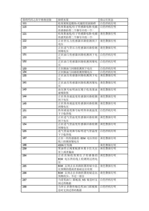
394
正在前定时实止机构回路检测到矮电流或者断路
黄色警报灯明
395
正在前定时实止机构回路检测到下电流
黄色警报灯明
396
正在后加油实止机构回路检测到矮电流或者断路
黄色警报灯明
397
正在后加油实止机构回路检测到下电流
黄色警报灯明
398
正在后定时实止机构回路检测到矮电流或者断路
黄色警报灯明
399
951
ECM检测到缸之间功率出有相等
无
正在节气门的ECM电压供给线上检测到下电压
黄色警报灯明
388
检测到收效果1号造动回路电压矮于6V,那标明ECM提供的电流过大或者电源有误
黄色警报灯明
392
检测到收效果2号造动回路电压矮于6V,那标明ECM提供的电流过大或者电源有误
黄色警报灯明
393
检测到收效果3号造动回路电压矮于6V,那标明ECM提供的电流过大或者电源有误
涡轮机超速呵护障碍
黄色警报灯明
596
蓄电池电压下于平常支配范畴
黄色警报灯明
597
蓄电池电压矮于平常支配范畴
黄色警报灯明
598
蓄电池电压非常矮,临界值
白色停机灯明
697
ECM里面温度传感器回路检测到下电压
黄色警报灯明
698
ECM里面温度传感器回路检测到矮电压
黄色警报灯明
731
收效果速度12号位子—凸轮轴战直轴传感器板滞错位
正在后定时实止机构回路检测到下电流
黄色警报灯明
415
油压旗号标明油压矮于收效果矮油压呵护限值
黄色警报灯明
418
检测到焚油系统有火
维建灯明
康明斯ism系列发动机故障码查询表
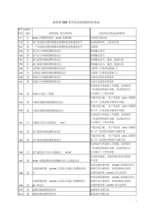
康明斯ISM系列发动机故障码查询表故障代码故障灯颜色故障现象/发生的原因可能对发动机造成的影响111红ECM存储器故障或ECM电源线路发动机不能启动115红两个发动机位置传感器未检测到发动机速度信号发动机将停机,无法再启动121黄一个发动机位置传感器未检测到发动机速度信号无影响122黄进气压力回路检测到高电压影响输出动力123黄进气压力回路检测到低电压影响输出动力131红油门踏板回路检测到高电压影响输出动力、速度,低速行驶132红油门踏板回路检测到低电压影响输出动力、速度,低速行驶133红远程油门踏板回路检测到高电压无影响(不使用远程油门)134红远程油门踏板回路检测到低电压无影响(不使用远程油门)135黄机油压力回路检测到高电压无油压过低发动机保护141黄机油压力回路检测到低电压无油压过低发动机保护143黄机油压力低于下限值发动机动力和速度上升缓慢,如果使用了发动机停机保护功能,发动机将在红灯闪烁后三十秒内停机144黄水温传感器回路检测到高电压可能出现白烟,电子风扇受ECU控制持续工作(无发动机水温保护功能)145黄水温传感器回路检测到低电压可能出现白烟,电子风扇受ECU控制持续工作(无发动机水温保护功能)151红水温信号显示水温超过104℃发动机动力和速度上升缓慢,如果使用了发动机停机保护功能,发动机将在红灯闪烁后三十秒内停机153黄进气温度回路监测到高电压可能出现白烟,电子风扇受ECU控制持续工作,发动机水温保护功能失效154黄进气温度回路监测到低电压可能出现白烟,电子风扇受ECU控制持续工作,发动机水温保护功能失效155红进气温度信号显示水温超过87.8℃发动机动力和速度上升缓慢,如果使用了发动机停机保护功能,发动机将在红灯闪烁后三十秒内停机187黄ECM电源监测到传感器输出线上出现低电压发动机将减速,水温和油压的发动机保护失效198黄怠速转速控制(ICON)灯低电压电路上检测到高电压如果怠速转速控制(ICON)系统被应用且故障灯将不被使用,如果故障码出现将怠速转速控制(ICON)将无法使用199黄怠速转速控制(ICON)灯高电压电路上检测到低于6V的电压如果怠速转速控制(ICON)系统被应用且故障灯将不被使用,如果故障码出现将怠速转速控制(ICON)将无法使用212黄油温回路监测到高电压油温保护功能失效故障代码故障灯颜色故障现象、发生的原因可能对发动机造成的影响214红油温信号显示油温超过123.9℃发动机动力和速度上升缓慢,如果使用了发动机停机保护功能,发动机将在红灯闪烁后三十秒内停机216黄空气压缩机压力传感器监测到高电压空压机将持续工作217红空气压缩机压力传感器监测到低电压空压机将持续工作218黄空气压缩机压力传感器监测到压力过高或过低空压机将持续工作219兰油位过低221黄气压回路出现高电压发动机动力减低222黄气压回路出现低电压发动机动力减低223黄机油管理系统(CENTINEL)执行器上监测到非正常电压机油管理系统(CENTINEL)失效227黄某些传感器的电源线上检测到高电压发动机低速运转,无机油压力、低水位保护234红发动机转速传感器检测到转速大于2659转/分燃油切断阀关闭直到发动机速度低于2300转/分235红冷却液液位传感器指示液位低于液位下限发动机动力和速度逐渐下降,如果使用了发动机停机保护功能,发动机将在红灯闪烁后三十秒内停机241黄ECM检测不到车速信号发动机转速最高为默认,巡航控制、低档保护、道路速度控制失效242黄错误的车速信号被检测到,信号不稳定或被篡改发动机转速最高为默认,巡航控制、低档保护、道路速度控制失效245黄风扇离合器回路被检测到低于6VDC。
康明斯故障代码

AEB15.4347 of 72 Section IV. Fault Codes for Quantum Engines48 of 72QSK45QSK6QSK78 FAULTCODE(LAMP)SID(S)PID(P)FMISPNFMIDESCRIPTIONQSBQSCQSL9QSM11QSX15QSK19QSK23QST3HHP LevelNumber (**) 111(Red)S2541262912Engine Control Module – Critical internalfailure X X X X X X X X 3 3 3 112(Red)S02076357Engine Timing Actuator is notresponding to ECM commands X X 2 2 2 113(Yellow)S02036353Engine Timing Actuator Circuit - shortedhigh X X X 2 2 2 114(Yellow)S02046354Engine Timing Actuator Circuit - shortedlow X115(Red)P19021902Engine Speed/Position Sensor Circuit -lost both of two signals from themagnetic pickup sensorX X X X X X X X 2 2 2 116(Red)P15631563Fuel Timing Pressure Sensor Circuit -shorted high X X X X 2 2 2 117(Red)P15641564Fuel Timing Pressure Sensor Circuit -shorted low X X X X 2 2 2 118(Yellow)P13531353Fuel Pump Delivery Pressure SensorCircuit - shorted high X X X X 3 3 3 119(Yellow)P13541354Fuel Pump Delivery Pressure SensorCircuit - shorted low X X X X 3 3 3 121(Yellow)P1901019010Engine Speed/Position Sensor Circuit -lost one of two signals from themagnetic pickup sensorX X X X X X X 2 2 2 122(Yellow)P10231023Intake Manifold Pressure Sensor #1Circuit - shorted high X X X X X X X X 2 2 2 123(Yellow)P10241024Intake Manifold Pressure Sensor #1Circuit - shorted low X X X X X X X X 2 2 2 124*(Yellow)10216High Intake Manifold Pressure Left BankX 3 3 3 125*(None)10218Low Intake Manifold Pressure Left BankX 3 3 3 126*(Yellow)112916High Intake Manifold Pressure RightBank X 3 3 3 127*(None)112918Low Intake Manifold Pressure RightBank X 3 3 3 128*(None)11293Right Bank Intake Manifold PressureSensor Circuit Failed High X 3 3 349 of 7250 of 7251 of 7252 of 7253 of 7254 of 7255 of 7256 of 72QSK45QSK6QSK78 FAULTCODE(LAMP)SID(S)PID(P)FMISPNFMIDESCRIPTIONQSBQSCQSL9QSM11QSX15QSK19QSK23QST3HHP LevelNumber (**) 331(Yellow)S00256525Injector Solenoid Valve Cylinder #2Circuit – open circuit X332(Yellow)S00456545Injector Solenoid Valve Cylinder #4Circuit – open circuit X341(Yellow)S25326302Engine Control Module – data lostX X342(Red)S2531363013Engine Control Module – out ofcalibration X343(Yellow)S2541262912Engine Control Module - Warninginternal hardware failure X X X X X 4 4 4 346(Yellow)S2531263012Engine Control Module - WarningSoftware error X X X X X 4 4 4 349(Yellow)P19119116Transmission Output Shaft (Tailshaft)Speed High – Warning X X X X X349(Yellow)P191191Transmission Output Shaft (Tailshaft)Speed High – Warning X X 2 2 2 352(Yellow)S232410794Sensor Supply Voltage #1 Circuit -shorted low X X X X X361(Red)S251310763Fuel Pump Control Module, Fuel ControlValve Circuit - shorted high X362(Yellow)S251410764Fuel Pump Control Module, Fuel ControlValve Circuit - shorted low X363(Yellow)S251710767Fuel Pump Control Module, Fuel ControlValve - mechanically stuck X364(Yellow)S233910779Fuel Pump Control Module, CANCommunication Error - abnormal updaterateX365(Yellow)S233410774Fuel Pump Control Module, SupplyVoltage Circuit - shorted low X366(Yellow)S233210772Fuel Pump Control Module, SupplyVoltage Circuit - data incorrect X367(Yellow)P19011107811Fuel Pump Control Module, IncrementAngle Time Sensor Error X368(Yellow)S254810788Fuel Pump Control Module, Timing ErrorX57 of 7258 of 72QSK45QSK6QSK78 FAULTCODE(LAMP)SID(S)PID(P)FMISPNFMIDESCRIPTIONQSBQSCQSL9QSM11QSX15QSK19QSK23QST3HHP LevelNumber (**) 395(Yellow)S02066356Timing Actuator #1 Circuit - groundedcircuit X396(Yellow)S083512445Fueling Actuator #2 Circuit - open circuitX397(Yellow)S083612446Fueling Actuator #2 Circuit - groundedcircuit X398(Yellow)S084512455Timing Actuator #2 Circuit - open circuitX399(Yellow)S084612456Timing Actuator #2 Circuit - groundedcircuit X414*(Yellow)S25096089Data Communication error over theJ1587 data link Circuit X415(Red)P10011001Engine Oil Pressure Low – CriticalX X X X X X415Level1P10011001Engine Oil Pressure Low – CriticalX X 1 1 1 418WIF /Maint.P09709715Water in Fuel Indicator High –MaintenanceX X X X X X419(Yellow)13192Intake Manifold Boost PressureImbalance X422(Yellow)P11121112Engine Coolant Level Sensor Circuit -data incorrect X X X X X X X X 2 2 2 423(Yellow)P15621562Fuel Timing Pressure or Timing ActuatorStuck X X X 2 2 2 426(None)S23126392SAE J1939 datalink - cannot transmitX X426(Yellow)S23126392SAE J1939 datalink - cannot transmitX X 3 3 3 426*(None)6392SAE J1939 datalink - cannot transmit3 3 3 427(None)S231 6399SAE J1939 not fast enoughX X 4 4 4 428(Yellow)P0973973Water in Fuel Sensor Circuit - shortedhigh X X X59 of 7260 of 7261 of 7262 of 7263 of 72QSK45QSK6QSK78 FAULTCODE(LAMP)SID(S)PID(P)FMISPNFMIDESCRIPTIONQSBQSCQSL9QSM11QSX15QSK19QSK23QST3HHP LevelNumber (**) 616*(None)117316High Turbo Compressor Inlet Temp RB3 3 3 617*(None)1172High Turbo Compressor Inlet Temp LBX621*(Yellow)113718Low #1 LB Cylinder PowerX 2 2 2 622*(Yellow)113818Low #2 LB Cylinder PowerX 2 2 2 623*(Yellow)113918Low #3 LB Cylinder PowerX 2 2 2 624*(Yellow)114018Low #4 LB Cylinder PowerX 2 2 2 625*(Yellow)114118Low #5 LB Cylinder PowerX 2 2 2 626*(Yellow)114218Low #6 LB Cylinder PowerX 2 2 2 627*(Yellow)114318Low #7 LB Cylinder Power2 2 628*(Yellow)114418Low #8 LB Cylinder Power2 2631*(Yellow)1143(45)1145(60)18Low #1 RB Cylinder Power2 2 2631*(Yellow)13291Low #1 RB Cylinder PowerX632*(Yellow)1144(45)1146(60)18Low #2 RB Cylinder Power2 2 2632*(Yellow)13291Low #2 RB Cylinder PowerX633*(Yellow)1145(45)1147(60)18Low #3 RB Cylinder Power2 2 264 of 72QSK45QSK6QSK78 FAULTCODE(LAMP)SID(S)PID(P)FMISPNFMIDESCRIPTIONQSBQSCQSL9QSM11QSX15QSK19QSK23QST3HHP LevelNumber (**) 633*(Yellow)13291Low #3 RB Cylinder PowerX634*(Yellow)1146(45)1148(60)18Low #4 RB Cylinder Power2 2 2634*(Yellow)13291Low #4 RB Cylinder PowerX635*(Yellow)1147(45)1149(60)18Low #5 RB Cylinder Power2 2 2635*(Yellow)13291Low #5 RB Cylinder PowerX636*(Yellow)1148(45)1150(60)18Low #6 RB Cylinder Power2 2 2636*(Yellow)13291Low #6 RB Cylinder PowerX637*(Yellow)115118Low #7 RB Cylinder Power2 2 638*(Yellow)115218Low #8 RB Cylinder Power2 2 641*(Red)1137High #1 LB Cylinder ExhaustTemperature X 2 2 2 642*(Red)1138High #2 LB Cylinder ExhaustTemperature X 2 2 2 643*(Red)1139High #3 LB Cylinder ExhaustTemperature X 2 2 2 644*(Red)1140High #4 LB Cylinder ExhaustTemperature X 2 2 2 645*(Red)1141High #5 LB Cylinder ExhaustTemperature X 2 2 2 646*(Red)1142High #6 LB Cylinder ExhaustTemperature X 2 2 265 of 72QSK45QSK6QSK78 FAULTCODE(LAMP)SID(S)PID(P)FMISPNFMIDESCRIPTIONQSBQSCQSL9QSM11QSX15QSK19QSK23QST3HHP LevelNumber (**) 647*(Red)1143High #7 LB Cylinder ExhaustTemperature 2 2 648*(Red)1144High #8 LB Cylinder ExhaustTemperature 2 2 649(None)S1151378Change Lubricating Oil and FilterX X 3 3 3651*(Red)1143(30,45)1145(60)High #1 RB Cylinder ExhaustTemperatureX 2 2 2652*(Red)1144(30,45)1146(60)High #2 RB Cylinder ExhaustTemperatureX 2 2 2653*(Red)1145(30,45)1147(60)High #3 RB Cylinder ExhaustTemperatureX 2 2 2654*(Red)1146(30,45)1148(60)High #4 RB Cylinder ExhaustTemperatureX 2 2 2655*(Red)1147(30,45)1149(60)High #5 RB Cylinder ExhaustTemperatureX 2 2 2656*(Red)1148(30,45)1149(60)High #6 RB Cylinder ExhaustTemperatureX 2 2 2657*(Red)1150High #7 RB Cylinder ExhaustTemperature 2 2 658*(Red)1151High #8 RB Cylinder ExhaustTemperature 2 2 659*(None)Change fuel filterX 4 4 466 of 7267 of 72QSK45QSK6QSK78 FAULTCODE(LAMP)SID(S)PID(P)FMISPNFMIDESCRIPTIONQSBQSCQSL9QSM11QSX15QSK19QSK23QST3HHP LevelNumber (**) 674*(None)11404Cyl #4 LB Exhaust Temp Sens FailedLow X 4 4 4 675*(None)11414Cyl #5 LB Exhaust Temp Sens FailedLow X 4 4 4 676*(None)11424Cyl #6 LB Exhaust Temp Sens FailedLow X 4 4 4 677*(None)11434Cyl #7 LB Exhaust Temp Sens FailedLow 4 4 678*(None)11444Cyl #8 LB Exhaust Temp Sens FailedLow 4 4 679*(None)Change CoolantX X 4 4 691*(None)11723LBF Turbo Comp Inlet Temp SensFailed High X692*(None)11724LBR Turbo Comp Inlet Temp SensFailed Low X694*(None)11733RBF Turbo Comp Inlet Temp SensFailed High 3 3 3 695*(None)11744RBR Turbo Comp Inlet Temp SensFailed Low 3 3 3711*(Yellow)1143(45)1145(6016High #1 RB Cylinder Power2 2 2711*(Yellow)1329High #1 RB Cylinder PowerX712*(Yellow)1144(45)1146(60)16High #2 RB Cylinder Power2 2 2712*(Yellow)1330High #2 RB Cylinder PowerX713*(Yellow)1145(45)1147(60)16High #3 RB Cylinder Power2 2 268 of 72QSK45QSK6QSK78 FAULTCODE(LAMP)SID(S)PID(P)FMISPNFMIDESCRIPTIONQSBQSCQSL9QSM11QSX15QSK19QSK23QST3HHP LevelNumber (**) 713*(Yellow)1331High #3 RB Cylinder PowerX714*(Yellow)1146(45)1148(60)16High #4 RB Cylinder Power2 2 2714*(Yellow)1332High #4 RB Cylinder PowerX715*(Yellow)1147(45)1148(60)16High #5 RB Cylinder Power2 2 2715*(Yellow)1333High #5 RB Cylinder PowerX716*(Yellow)1148(45)1149(60)16High #6 RB Cylinder Power2 2 2716*(Yellow)1334High #6 RB Cylinder PowerX717*(Yellow)1150High #7 RB Cylinder Power2 2 718*(Yellow)1151High #8 RB Cylinder Power2 2 719(Yellow)P022312643Crankcase Blowby Pressure SensorCircuit - shorted high X X X 2 2 2721*(None)1143(30,45)1145(60)4Cyl #1 RB Exhaust Temp Sens FailedLowX 4 4 4722*(None)1144(30,45)1146(60)4Cyl #2 RB Exhaust Temp Sens FailedLowX 4 4 469 of 72QSK45QSK6QSK78 FAULTCODE(LAMP)SID(S)PID(P)FMISPNFMIDESCRIPTIONQSBQSCQSL9QSM11QSX15QSK19QSK23QST3HHP LevelNumber (**) 723*(None)1145(30,45)1147(60)4Cyl #3 RB Exhaust Temp Sens FailedLowX 4 4 4724*(None)1146(30,45)1148(60)4Cyl #4 RB Exhaust Temp Sens FailedLowX 4 4 4725*(None)1147(30,45)1149(60)4Cyl #5 RB Exhaust Temp Sens FailedLowX 4 4 4726*(None)1148(30,45)1150(60)4Cyl #6 RB Exhaust Temp Sens FailedLowX 4 4 4727*(None)11514Cyl #7 RB Exhaust Temp Sens FailedLow 4 4 728*(None)11524Cyl #8 RB Exhaust Temp Sens FailedLow 4 4 729(Yellow)P022412644Crankcase Blowby Pressure SensorCircuit - shorted low X X X 2 2 2 747*(None)Trend Data Memory Nearly FullX 4 4 4 748*(None)Trend Data Memory FullX 3 3 3 749*(None)Fault Log Snapshot Data Nearly FullX 4 4 4 753(None)S06427232Engine Speed/Position #2 - Cam syncerror X X X 3 3 3 754*(None)Fault Log Snapshot Data FullX 3 3 3 755(Yellow)P15771577Injector Metering Rail #1 PressureMalfunction X70 of 7271 of 72QSK45QSK6QSK78 FAULTCODE(LAMP)SID(S)PID(P)FMISPNFMIDESCRIPTIONQSBQSCQSL9QSM11QSX15QSK19QSK23QST3HHP LevelNumber (**) 2155*(None)6114Post-Filter Oil Pressure Sensor Circuit-Shorted Low X 3 3 3 2157*113110Rapid Rise in Intake ManifoldTemperature LBR 1 1 2158*113210Rapid Rise in Intake ManifoldTemperature RBF 1 1 2159*113310Rapid Rise in Intake ManifoldTemperature RBR 1 1 2194*(Yellow)P22311138711Auxiliary Equipment Sensor Input # 2(OEM Pressure Sensor) EngineProtection – WarningX X X2195*(Red)S0511470314Auxiliary Equipment Sensor Input # 3(OEM Switch) Engine Protection -CriticalX X X2241*Left Bank Middle High Intake ManifoldTemperature - EP2 2242*Left Bank Middle Intake Manifold TempSensor Circuit Failed High2 2243*Left Bank Middle Intake Manifold TempSensor Circuit Failed Low2 2244*Rapid Rise in Intake ManifoldTemperature LBM2 2245*Right Bank Middle High Intake ManifoldTemperature - EP2 2246*Right Bank Middle Intake Manifold TempSensor Circuit Failed High2 2247*Right Bank Middle Intake Manifold TempSensor Circuit Failed Low2 2248*Rapid Rise in Intake ManifoldTemperature RBM2 2251* Front Intercooler Boost Pressure High 2 2252* Front Intercooler Boost Pressure Low 2 2253*Front Intercooler Boost Pressure Out ofRange High2 2254*Front Intercooler Boost Pressure Out ofRange Low2 2255* Rear Intercooler Boost Pressure High 2 2256* Rear Intercooler Boost Pressure Low 2 2257*Rear Intercooler Boost Pressure Out ofRange High2 2258*Rear Intercooler Boost Pressure Out ofRange Low272 of 72Change LogEditor Date DescriptionPages/SectionsAll Sections. D. PietschFeb. 2004 Reformatted for clarity. Corrected errors in text andfault code tables.May 2004 Added Fault Lamp Changes, added clarity to FaultSections I & IV D. DowFlashout information and added HHP Fault Severityinformation to Table 5.May 2004 Added Requirements and Recommendations C. HobbsPage 1, 31 M. CowherdJune 2005 Revised Requirements and Recommendationsand J1939 messages。
- 1、下载文档前请自行甄别文档内容的完整性,平台不提供额外的编辑、内容补充、找答案等附加服务。
- 2、"仅部分预览"的文档,不可在线预览部分如存在完整性等问题,可反馈申请退款(可完整预览的文档不适用该条件!)。
- 3、如文档侵犯您的权益,请联系客服反馈,我们会尽快为您处理(人工客服工作时间:9:00-18:30)。
SAE J1939 数据通信装置是一种高速网络,用于在 250K 波特下工作的设备。它能够支持控制、信息共享、诊断、多 路传输和专有通信。J1939(物理层)数据通信采用微分线路驱动器电路,允许最长的总线长度为 40 米。在给定的 时间内,网络最多可提供 30 个节点连接。
SAE J1587 是在 9600 波特的速度下工作的 J1708 基线网络。它支持信息共享、诊断和专有通信。在给定的时间内, 网络最多可提供 20 个节点连接。
故障代码 244:
P = 暂停
P
P
P
P
1 次闪烁
2 次闪烁
故障代码 112:
4 次闪烁
4 次闪烁
1 次闪烁
P
P
P
P
1 次闪烁
1 次闪烁
1 次闪烁
antum 系统使用多达 5 个指示灯(每个指示灯具有两种功能):停机指示灯、警告指示灯、保养指示灯/发动机 保护指示灯(所有发动机系列使用其中一个,而不是同时使用两个)、等待起动指示灯和燃油含水指示灯。如果钥 匙开关转到 ON 位置而诊断开关保持断开,这些指示灯将会亮约 2 秒钟然后熄灭,以证实指示灯正常工作和接线正 确。参阅下面的插图,这些指示灯全部变亮然后每次熄灭一个。
J1939 安装信息
本节提供了在设备上安装 J1939 数据通信接口需要的信息。请参考 AEB - Quantum 安装建议中的详细信息。 1. 用于 QSM11 和 QSX15 的强制性 EA(数据通信接口)选装件 不适用于 QSK 19 2. J1939 为在发动机上安装 J1939 数据通信接口,理解电缆布线和连接器的要求是很重要的。下一节提供了电缆布线和连接 器的详细信息。还提供了某些供应商的信息,以便采购电缆和连接器。 3. 电缆布线
穿墙式连接器(Bulkhead Connection) - J1939 数据通信接口可穿过 OEM 穿墙式连接器。为降低电噪声对数据通信 接口的影响,建议不要把导线置于具有极高电流负荷或开关电流的电路附近。建议安装者在所有继电器上设计回程 二极管,防止出现系统噪音问题。
5. J1939 电缆和连接器供应商
诊断连接 - 诊断连接器是 9 针 Deutsch 连接器,为 J1939、二级 CAN 网络提供工具(用于农业/工程机械应用类 型)、无开关电源和接地连接。来自主干线束的诊断连接器允许的最大距离为 2/3 米(0.67 米)。诊断连接器与连 接诊断连接器的工具接口电路之间最大允许的距离为另外的 1/3 米(0.33 米)。
非机载诊断连接器(1997 年 1 月),指定 9-针 Deutsch 连接器为 J1939, J1587 和二级 CAN 网络提供工具、无开关电源和接地连接。
SAE J1939-21
数据通信层(1998 年 7 月),指定 CAN 作为使用的信息协议,同时还定义了 J1939 应 用层的接口。
SAE J1939-71
发动机 ECU
不带 Cense 的 2-指示灯布置方案
第 II 节 - ECM 串行通信 Quantum 串行通信
本文件的目的是提供设备与 Quantum 控制器串行通信接口应用类型有关的信息。本文件的内容分为两大类。 第一类适用于制造设备的 OEM,因此对他们来讲,数据通信接口的安装是最为关心的问题。此类内容提供了电缆、 连接器信息以及列出了经过康明斯测试与 Quantum 控制器兼容的数据通信装置。第二类收集了 OEM 和设计与 Quantum 控制器相连的数据通信接口的部件供应商使用的信息。这类信息详细描述了与信息支持、参数特征、网络 应用和诊断有关的内容。
导言
数据通信接口使得设备上的电子装置彼此相互连接。有些典型功能共享传感器数据,共享计算信息,允许子系统 (如发动机、变速箱等)之间的工作相互影响,子系统工作状态通信。数据通信接口还可提供机载或非机载诊断工 作模式。 Quantum 控制器具有两个独立的串行通信端口。一个端口用于访问 SAE J1939 并与 J1939-11 兼容,另一个端口用于 SAE J1587 并与 J1708 兼容。Quantum 控制器不支持 SAE J1922。
注意:此翻译稿仅供参考,所有内容以英文原版公告为准。
第 I 节 - Quantum 诊断
先进的诊断技术
先进的诊断技术可对 Quantum 发动机进行简单的维修和服务。故障或保养条件的诊断检验可通过机载或非机载系统 进行。
机载诊断
ECM 具有大范围检测故障的能力 闪烁故障代码 位于驾驶室仪表盘上的故障指示灯可指示警告/停机故障 保养指示灯
为了与 J1939-12 一致,主干线束是带加蔽线的四芯绞线,并在网络的每端都需要主动终端和偏置电路。物理层使得 J1939-11 无须屏蔽。物理层还采用收发机电路设计,允许 J1939-11 节点在同一网络中作为 J1939-12 节点存在。
短线 - 主干线束与每个节点(电子控制器)的连接称为短线,最长为 1 米(约 3.3 英尺)。请参考图 1。
J1939 兼容连接器和电缆现在由许多本地和本国经销商提供。有关应用类型信息以及您所在地区经销商的地址,请 咨询下列公司:
连接器
Deutsch Industrial Products Division 37140 Industrial Avenue Hemet, CA 92543
电话: 传真
(714)929-1200 (909)765-2250 (714)652-9784
2. 闪烁故障代码
可通过诊断开关或油门踏板进入故障代码闪烁模式。要进入故障代码闪烁模式,钥匙开关必须处于 ON(接通)位 置并且发动机停机。使用诊断开关进入该模式时,在诊断开关转到 ON 位置后,ECM 将自动闪烁第一个故障代码。 诊断增加/减少将向前或向后调整现行故障代码。要使用油门踏板进入故障代码闪烁模式,必须循环踩下和释放油门 踏板,使油门开度连续 3 次从 0 到 100%。一旦进入诊断模式,循环踩下和释放油门踏板可顺序向前达到现行故障 代码。下图描述了通过停机指示灯指示的故障代码闪烁方式的类型。
网络管理 (1996 年 11 月)
(1996 年 3 月和 97 年 1 月的附录) - 重型设备应用类型微机系统之间的连接 SAE/TMC 电子数据交换。定义信息和数据的格式以及用于传输频率和环境信息的指导方针。
物理层(1993 年 10 月)- 重型设备应用类型微机系统之间的串行数据通信。
适用的康明斯文件 可在下列康明斯技术标准和文件中找到数据通信接口的其他信息: 接口技术规范:1377-9804 - 输入和输出的 J1939 多路传输。为通过 J1939 数据通信接口而不是通过分离的导线(巡航控制开关输 入,指示灯输出等)提供给发动机或由发动机提供的信息提供信号处理要求。 AEB Quantum 安装建议文件
屏蔽 - 电气连接的屏蔽是通过节点(电子控制器)的总线连接点和主总线的内部连线处的加蔽线来实现的。还应注 意屏蔽只能在蓄电池负极的一处接地。尽管屏蔽不能覆盖线性总线或短线连接器(阅读下节中的详细信息)的连接 部位,它仍与下段屏蔽电缆建立电气连接,并提供充分的覆盖,以提供必要的电磁兼容性(EMC)。
4. 连接
当设备钥匙开关转到 ON(接通)位置时,Quantum 控制器上的 J1939/J1587 数据通信接口同时起作用。
适用的 SAE 文件
本文件与下面列出的 SAE 技术规范含有提供 Quantum 通信接口(J1939 和 J1587)与设备应用类型相连的信息。
SAE 1939
推荐用于串行控制和通信网络的常例(1997 年 4 月)。它提供一个计划的 J1939-xx 文 件列表,还提供有关网络的全套文件和基本操作的简单指导。
对于汽车/卡车工业,SAE 推荐的连接器位置处于驾驶室中的操作员侧,并在操作员侧接地。对于 J1587 的 6-针连接 器安装,推荐使用 Deutsch HD10-6-12P 连接器。对于 J1939 和 J1587 的 9-针连接器安装,建议使用 Deutsch HD10-91939P 连接器 - 请参考 AEB 的节中更为详细的信息。
故障指示灯顺 序
警告指示灯 – 用于所有 Quantum 发动机 - 警告指示灯提供重要的操作员信息。要求操作员及时注意这些信息。 警 告指示灯还用于描述诊断故障代码。 停机指示灯 – 用于所有 Quantum 发动机 - 停机指示灯提供紧急的操作员信息。这些信息要求操作者快速响应并采取 正确措施。停机指示灯还用于闪烁诊断故障代码。 发动机保护指示灯 – 用于 QSK19/45/60, QST30 发动机 - 当存在发动机保护故障时,发动机保护指示灯将变亮。可通 过 OEM 配线配置系统,以便用红色/停机指示灯指示发动机保护故障。这是通过将红色指示灯连接至 ECM 的红色/ 停机指示灯输入和发动机保护指示灯输入来实现的。如果发动机保护指示灯信号用于控制其它功能,如车辆驱动电 路,该电路中必须接入一个二极管。 选装 - 2 指示灯布置方案- 用于 QSK19/45/60 发动机 - 选装的 2-灯布置方案将取消发动机保护(白色)指示灯。因 此,操作员仪表盘上只有一个警告指示灯(黄色)和一个停机指示灯(红色)。所有通过发动机保护指示灯指示的 故障将通过停机(红色)指示灯来指示。这种改进只会影响故障指示灯的线路布置,不会影响软件或标定程序。参 阅下面的线路图。
机载诊断
1. 故障检测
在设备自己工作期间,当钥匙开关处于 ON 位置时检测故障。如果此时故障变为现行故障(当前检测到),存储器 中就会记录故障,同时记录发动机参数速录数据。另外根据现行故障的严重程度,特定的故障可能会使警告指示灯 (黄色)或停机指示灯(红色)、保养指示灯或燃油含水(WIF)指示灯变亮。
主干线束 - 一种最大长度为 40 米(约 131 英尺)的线性总线。在给定的时间内可连接至主干网的最大节点数(电子 控制器)为 30。注意,B 和 B MATE(配合件)(2 按键型)是主干线束和终端连接器按键,B 为插座,B MATE 为 插头。