席宗龙老师团队目标100%达成超强凝聚力(三天二夜)
Recom RP100H-RW DC DC 转换器产品说明书

FeaturesRegulated Converter• 4:1 wide input range• 3kVAC reinforced insulation for 110Vin 2.25kVDC basic insulation for 24Vin & 48Vin • Efficiency up to 93%• No minimum load required• EN50155, IEC/EN60950-1 & UL60950-1 certifiedDescriptionThe half-brick RP100H series DC/DC converters are designed for railway rolling stock and high voltage battery applications. Each series has three 4:1 input voltage range options to cover all input voltages from 9VDC up to 160VDC with isolated and regulated 5V to 48VDC outputs. The converters have high efficiencies and metal base-RP100H-RW DC/DC Converter100 Watt Half BrickEN50155 certifiedIEC/EN60950-1 certified UL60950-1 certifiedE196683RP100H-2415SRW 9-36 15 6700 4601 100 91 4460RP100H-2424SRW 9-36 24 4200 4666 101 90 1750RP100H-2448SRW 9-36 48 2100 4666 101 90 430RP100H-4805SRW 16.5-75 5 20000 2240 100 93 40000RP100H-4812SRW 16.5-75 12 8400 2333 101 90 7000RP100H-4815SRW 16.5-75 15 6700 2300 100 91 4460RP100H-4824SRW 16.5-75 24 4200 2333 101 90 1750RP100H-4848SRW 16.5-75 48 2100 2307 101 90 430RP100H-11005SRW 43-160 5 20000 1010 100 93 40000RP100H-11012SRW 43-160 12 8400 1018 101 90 7000RP100H-11015SRW 43-160 15 6700 1015 100 91 4460RP100H-11024SRW 43-160 24 4200 1018 101 90 1750RP100H-11048SRW 43-160 48 2100 1007 101 90 430Ordering ExamplesRP100H-2405SRW/N = 24V Input, 5V Output, Single, Neg. CTRL function RP100H-11012SRW/P = 110V Input, 12V Output, Single, Pos. CTRL functionRP100H-2405SRW/N-HC = 24V Input, 5V Output, Single, Neg. CTRL function, premounted Heat-sinkModel NumberingInput Voltage Output VoltageS ingleRP100H-__ __SRW/_ _Notes:Note2: standard part is with suffix “P” for positive logic (1=ON, 0=OFF) or add suffix “N” instead for negative logic (0=ON, 1=OFF) Note3: add suffix “-HC” for premounted Heat-sink CTRL Logic (2)Package (3)Notes:Note1:Efficiency is tested by nominal Vin, full load and at 25°Chttps:///pdf/Powerline_DC-DC/RSPxxx-168.pdf/eval-ref-boardsSpecifications (measured @Ta = 25°C, resistive load, nominal Vin and rated Iout unless otherwise noted)Specifications (measured @Ta = 25°C, resistive load, nominal Vin and rated Iout unless otherwise noted)RP100H-4805SRW708090100Efficiency vs. Output CurrentPower up Start-up CharacteristicON/OFF Control Start-up Rise CharacteristicSpecifications (measured @Ta = 25°C, resistive load, nominal Vin and rated Iout unless otherwise noted)Efficiency vs. Input Voltage60708090100708010090RP100H-11005SRWEfficiency vs. Output CurrentPower up Start-up CharacteristicSpecifications (measured @Ta = 25°C, resistive load, nominal Vin and rated Iout unless otherwise noted)OUTPUT TRIM Typical Output Ripple and NoisePower up Start-up CharacteristicOutput Voltage TrimmingRP100H-RW converters offer the feature of trimming the output voltage over a certain range around the nominal value by using external trim resistors. The values for trim resistors shown in trim tables below are according to standard E96 values; therefore, the specified voltage may slightly vary; they also can be calculated with below shown equation.TRIM DOWNTRIM UPTRIM-Sense+SenseSpecifications (measured @Ta = 25°C, resistive load, nominal Vin and rated Iout unless otherwise noted)OUTPUT TRIMRP100H-xx05SRWRP100H-xx12SRWRP100H-xx15SRWRP100H-xx24SRWRP100H-xx48SRWTrim Down all Vout‘sTrim up 12345678910%Vout = 5.05 5.10 5.15 5.20 5.25 5.30 5.35 5.4 5.45 5.50Volts R 1 = 30915810578.763.453.646.440.236.533.2kOhms Trim up 12345678910%Vout =12.1212.2412.3612.4812.6012.7212.8412.9613.0813.20Volts R 1 = 88745330122618215413311810595.3kOhms Trim up 12345678910%Vout =15.1515.3015.4515.6015.7515.9016.0516.2016.3516.50Volts R 1 = 1130576383294237196169150137124kOhms Trim up 12345678910%Vout =24.2424.4824.7224.9625.2025.4425.6825.9226.1626.40Volts R U = 1870953634487392324280249226205kOhms Trim up 12345678910%Vout =48.4848.9649.4449.9250.4050.8851.3651.8452.3252.80Volts R 1 = 3830196013001000806681576511464422kOhms Trim down 12345678910%R 2 = 97.647.531.623.217.814.712.110.59.098.06kOhms Trim down 11121314151617181920%R 2 =7.156.345.765.114.644.223.923.573.243.01kOhmsTrim CalculationVout = Output VoltageR 1 =100*Vout+D Vout * Vout)- (100+2D Vout) k Ω D Vout = Output Voltage Trim in %1.225*D Vout D VoutR1 =trim up resistorR2 = trim down resistor R 2 = 100 - 2 k ΩD Vout Practical Example:Trim Up:Vout = 5V, D Vout = 10% (5.5V)R 1 =100*Vout+D Vout * Vout) - (100+2D Vout) k Ω = 100*5 +10*5 - 100+2*10= 44.89 - 12 = 32.9k Ω 1.225*D Vout D Vout 1.225*10 10Trim down:Vout = 5V, D Vout = -10% (4.5V)R 2 = 100 - 2 k Ω = 100 - 2 = 8.06k ΩD Vout 10Specifications (measured @Ta = 25°C, resistive load, nominal Vin and rated Iout unless otherwise noted)REGULATIONSParameter Condition ValueOutput Accuracy±1.0%Line Regulation low line to high line at full load±0.1% Load Regulation0% to 100% load0.1% Transient Response25% load step change200µs typ.; 250µs max.Transient Response to Dynamic Load Change from 100% to 75% to 100% of Full Load at nom.VinRP100H-4805SRWRP100H-2405SRWRP100H-11005SRWSpecifications (measured @Ta = 25°C, resistive load, nominal Vin and rated Iout unless otherwise noted)ENVIRONMENTALParameterCondition ValueOperating Case Temperature Range refer to derating graphMaximum Case Temperature 105°CTemperature Coefficient ±0.02%/°C max.Thermal Impedance vertical direction by natural convection (0.1m/s) without Heat-sink vertical direction by natural convection (0.1m/s) with Heat-sink6.7°C/W 4.7°C/W Operating Humidity 5% - 95% RHPollution Degree PD2Shock according to EN61373 standard Thermal Shock according to MIL-STD-810F standardVibrationaccording to EN61373 standardFire protection on railway vehicles according to EN45545-2, 2013 standardMTBFaccording to MIL-HDBK-217F standard, 25°C408.7 x 103 hoursPROTECTIONSParameterConditionValueShort Circuit Protection (SCP)below 100m Ωcontinuous, automatic recovery Over Voltage Protection (OVP)% of nom. Vout115%-130%, Hiccup Mode Over Load Protection (OLP)% Iout rated24Vin, 48Vin 110Vin120%-150%, Hiccup Mode 150% typ., Hiccup ModeOver Temperature Protection (OTP)+110°C to +120°C Isolation Voltage110VinI/P to O/P I/P or O/P to Case 3kVAC/1minute 1.5kVAC/1minute 24Vin, 48VinI/P to O/P I/P or O/P to Case2.25kVDC/1minute 1.6kVDC/1minuteIsolation Resistance 500 VDC1G Ω min.Isolation Capacitance 2500pF max.Isolation Grade110 Vin 24Vin, 48Vin reinforced insulationbasic insulationThermal CalculationNotes:Note4: Refer to local wiring regulations if input over-current protection is also required. Recommended fuse: T35A slow blow.R thcase-ambient = 6.7°C/W (vertical) T case = Case Temperature R thcase-ambientHC = 4.7°C/W (vertical) T ambient = Environment Temperature P dissipation = Internal lossesR thcase-ambient = T case - T ambientP IN = Input PowerP dissipationP OUT = Output Power h = Efficiency under given Operating ConditionsP dissipation = P IN - P OUT = P OUTapp- P OUTapp R thcase-ambient = Thermal Impedance h Practical Example:Take the RP100H-2405SRW with 9V input Voltage and 50% load. What is the maximum ambient operating temperature? Use converter vertical in application without airflow.Eff min = 91% @ V nomP OUT = 100W P OUTapp = 100 x 0.5 = 50W h = 91% (Efficiency vs. Load Graph)without Heat-sink with Heat-sinkR th = T casemax - T amb --> 6.7°C/W = 105-T amb R thHC = T casemax - T amb--> 4.7°C/W = 105-T amb P dissipation 4.95W P dissipation4.95W T amb = 72°C T ambHC = 82°CSpecifications (measured @Ta = 25°C, resistive load, nominal Vin and rated Iout unless otherwise noted)Specifications (measured @Ta = 25°C, resistive load, nominal Vin and rated Iout unless otherwise noted)DC/DC ConverterSpecifications (measured @Ta = 25°C, resistive load, nominal Vin and rated Iout unless otherwise noted)RP100H-RWSeriesConducted Emission EN55022 Class AConducted Emission EN55022 Class AC4C5C6C7C8Shield PlaneL1C18+V INEMI Filtering according to EN55022/11 Class A and EN50121-1 (110Vin)DC/DC ConverterSpecifications (measured @Ta = 25°C, resistive load, nominal Vin and rated Iout unless otherwise noted)RP100H-RWSeriescontinued on next pageEMI Filtering according to EN55022/11 Class B (24Vin and 48Vin)Shield Plane100-110xxSRW, Class BNNC6C9C8C3C4CaseL2C7C19C20Shield PlaneC12C13C14C10C11C16C2C4L1L2C5C8C6C7C11C3Conducted Emission EN55022 Class ADC/DC ConverterSpecifications (measured @Ta = 25°C, resistive load, nominal Vin and rated Iout unless otherwise noted)RP100H-RWSeriesEMI Filtering according to EN55022/11 Class B (110Vin)C8Shield PlaneShield PlaneC9C1C2C3C11C12C10CaseL1C4C5C8C13C14C17C9C19C3C4L1L2C12C10C11C15C15Shield PlaneC9C10C12Conducted Emission EN55022 Class BSpecifications (measured @Ta = 25°C, resistive load, nominal Vin and rated Iout unless otherwise noted)Specifications (measured @Ta = 25°C, resistive load, nominal Vin and rated Iout unless otherwise noted)The product information and specifications may be subject to changes even without prior written notice.The product has been designed for various applications; its suitability lies in the responsibility of each customer. The products are not authorized for use in safety-critical applications without RECOM’s explicit written consent. A safety-critical application is an application where a failure may reasonably be expected to endanger or cause loss of life, inflict bodily harm or damage property. The applicant shall indemnify and hold harmless RECOM, its affiliated companies and its representatives against any damage claims in connection with the unauthorizeduse of RECOM products in such safety-critical applications.PACKAGING INFORMATIONParameterTypeValuePackaging Dimension traywithout Heat-sink with Heat-sink157.0 x 88.0 x 12.8mm 157.0 x 88.0 x 24.8mmPackaging Quantity 2pcs.Storage Temperature Range -55°C to +125°C Storage Humidity5% - 95% RH。
赫特尔 HPC-100CT-2系列胶囊式水位传感器说明书

Doc. no : HT(HPC)100CT2_IM_Eng_Rev.2Issue date: 2020. 02HITROL CO., LTD.HEAD OFFICE.FACTORY .R&D INSTITUDE HITROL CO.,LTD. 141, Palhakgol-gil, Jori-eup Paju-si, Gyeonggi-do, Korea TEL. : (00)-82-31-950-9700 FAX. : (00)-82-31-943-5600 INSTRUCTION MANUALCAPACITANCE TYPE LEVEL TRANSMITTERHT-100CT-2 Series HPC-100CT-2 SeriesTable of contentsOverview (3)Characteristics (3)Operating Principle (3)Specifications (4)Weather-Proof Version (4)Ex -Proof Version (4)Amplifier Specification (5)Product Composition & Technical Data (6)Installation (8)Metal Tanks (10)Non-metal Tanks (10)Wiring & AMP Composition (11)Failure Check & Maintenance (18)Product Check (18)Failure Check (18)Precautions for Removal (18)Precautions for Transportation & Assembly .. 19 Precautions for Installation (19)Precautions for Grounding ......... 19 Safety and Environment (19)Marking (20)User Training (20)Warranty and Contact (20)OverviewCharacteristicsOperating Principle■Widely used to measure various liquid levels■Strong structure and semi-permanent life cycle due to moveless part■Various probe types for wide application■Easy installation of wire type. (HT-100CTW-2)■Applicable to corrosive liquid■Interface measurement between water and oil is available■Applicable to explosive area (HPC-100CT-2 Series)■Have KC certificate and CE certificateHT(HPC)-100CT-2 Series is a Capacitance Type Level Transmitter which continuously measures liquid levels using of liquid’s dielectric constant. It can be easily installed and adjusted, and can be easily applied to corrosive liquids and widely used in general industries, chemical and oil plants.When there are two conductors insulated each other, the value of capacitance formed between two conductors is a function of the sizes of two conductors, relative location of two conductors and the dielectric constant of material placed between two conductors. Under the conduction that air of dielectric ε₁exists in the space between two concentric conductors, lower part of space between two conductors is filled material of dielectric constant ε₂as shown below, the change of capacitance is expressed as follows.ΔC =Since is a constant value as an initial condition, and get this value as K, ΔC becomes a function of level of material only. Therefore, level can be obtained through the measurement of ΔC.log D/d10(ε₂- ε₁X l)[pF]10log D/d(ε₂- ε₁): Dielectric constant of air: Dielectric constant of medium (contents): Height of tank: Level of medium (contents): Outer diameter of tank: Outer diameter of sensing probeε₁ε₂LIDdSpecifications Weather-Proof VersionEx-Proof VersionAmplifier SpecificationProduct Composition & Technical DataMaterial :PBT(Aluminum) [Housing][Connection] Material : AluminumDielectric Constant Valuewebsite .InstallationThe capacitance type level transmitter can be installed in screw (PT, NPT, PF) and flange (ANSI, JIS, DIN) as well as tri-clamp and other various locations. Pay attention to the following matters during installation.■ Product shall be installed at the place far from inlet in order to avoid the malfunction.(a) ■ Protection tube shall be applied if there is a flow or slopping of the medium of the tank. (b) ■ Probe shall be installed within Max. 300mm from the tank wall and ground tube type shall be applied if the distance between the tank wall and sensing probe is far or the tank material is non-conductive. (c)■ Ground rod type shall be used for corrosive liquid. (d)■ Bracket insulated to a sensing probe shall be installed at the bottom of probe in order tofix it if the probe length is long or there is slopping of medium in the tank. (e)■ Ground tube or ground rod type shall be applied for concrete or non-conductive tank as per above figure. (g)■ Ground tube type shall be applied for ball tank and external chamber shall be installed forside mounting of tank. (h)■ When side mounting, the chamber shall be installed. (i)(g)(i)(h)■Metal Tanks (Conductive tank)When installing on a conductive tank, the transmitter housing and tank shall be grounded as shown below.■Non-metal tanks (Non-conductive tank)When installed on a non-conductive tank, use the ground tube (rod) or ground wire type.Also, the transmitter housing and tank shall be grounded as shown below.Wiring & AMP Composition■ Set Menu Function: Level : Distance0.0 ~ 95.0% or 4.000 ~ 19.200 mA setting [T able 1] Setting Menu List■ Module Composition- Make sure to connect the power with correct polarity (+, -), and the power supply shall be between +17V ~ 40V . - Do not connect the wire with the power connected.1. S : Function setting / Save the setting2. M : Mode Change / Cancellation3. ▲ : Span Set / Setting the value left / up4. ▼ : Zero Set / Setting the value right / down5. LCD : Display of operating and setting status6. LED : Display of power and status7. UART : Communication port of HT-100CT-2 setup and operation status 8. PWR : For supply power and current output / check for output current 9.N/A : Not used■ Operating methodThe cursor moves sequentially whenever the button is pressed. The order of movement is as follows.mA → % → m → ft → → → mA → % →…□ Into the Setting MenuIn the Setting Mode, press button for 1 second then the green LED will be flickering and you can go into the Setting Menu.□ Return to the Setting ModeIn the Setting Menu, press button for 1 second then the green LED will be flickering and you can go back to the Setting Mode.□ Select the Setting Menu⏹ In the Setting Menu, use / buttons to select the user setting function. ⏹Pressingbutton for 1 second will enter the function.About 1 sec./About 1 sec.About 1 sec. Display mode Cursor SegmentBar graph(User setting)(User setting)□ Change the User SettingIf just 1 digit is flickering , it can be moved between the digits. If full digits are flickering , it can only be set up to the specified number.□ User Key Button■ Height SettingChange of digitsand valueLevelThis refers to the direction in which the medium is raised based on the bottom of the tank.Zero HeightThe distance from the bottom of the tank to the zero point is called “Zero Height ”.Span HeightThe distance from the bottom of the tank to the span point is called “Span Height ”.T ank HeightThe distance from the bottom of the tank to the top of the tank is called “T ank Height DistanceThis refers to the direction of the downing of the medium from the top of the tank.[T able 2] Key Button Guidance□ Zero, Span Quick Setting■ Zero Setting■ Span Setting■ Others▶ Zero & Span can be set regardless of display mode status▶ It can set, save, and cancel the values. (Refer to T able 2) ▶ The level shall not be changed when Zero & Span are setting.mA SettingPercent Setting■ UART MonitoringYou can only check the state of the adjusted setting values using your PC or Smartphone, and the execution method is the same. (Password: 1975)Run screen configuration: You can check the sensor measurement status, sensitivity setting value, relay setting status, etc.■ Monitoring using a PCComponent – PC, USB Extension cable (typical USB to Micro USB B), UART ADAPTORZero SettingSpan SettingPress for 1 sec.Press for 1 sec.Press for 1 sec.Press for 1 sec.Input the valueInput the value[USB Extension cable][HT-100CT-2 PC UART Compositions]No. No. ContentsContentsSettingSetting[HT-100CT-2 PC UART Launch Screen Compositions]OutputInput[A Description of the Current Operating Status (##Err State)][HT-100CT-2 PC UART Launch Screen Compositions Function]Unit SetSetSet SetHeight Set (Based on level)Height Set (Based on level) Height Set (Based on level)Function SetSetAdjustmentAdjustmentAdjustmentSelectResetCapacity Value of Current MeasuredCapacity Value of Span SettingCapacity Value of Zero SettingCurrent Output of Current V alue (01. B a s e d o n O u t p u t S e l e c t S e t t i n g ) Current Output of P ercentage V alue (01. B a s e d o n O u t p u t S e l e c t S e t t i n g )Current Output of Length V alue (01. B a s e d o n O u t p u t S e l e c t S e t t i n g )Current Output of Feet V alue (01. B a s e d o n O u t p u t S e l e c t S e t t i n g )Current Operating StateNormal operationProblem for sensing B el ow or ab ov e t he set v a l ue o f Z er o or S p a n Abnormal settingSensor cable open circuit, short, broken probe insulation, module sensor failure, etcNAMUR ME43 Caution area (below 4mA, above 20mA)Zero, Span conversely set stateNo.ContentsDescriptionRemarks■Monitoring using a SmartphoneComponent – Smartphone (Android OS), OTG, USB Extension cable (typical USB to Micro USB B), UART ADAPTORApplication – Refer to “Serial USB Terminal Install & Setting Guide”[USB Extension cable][HT-100CT-2 Smartphone UART Compositions][Enter PW and Fly command]Continue[Open App] [Home screen] [Select the UART Connection] [Enter the password] [Operation screen][HT-100CT-2 Smartphone UART Launcher][Enter exit and Fly command][Enter exit command] [End of program] [Select the UART Disconnection][HT-100CT-2 Smartphone UART Exit]Failure Check & MaintenancePrecautions For Removal ■Check the level and presence of medium in the tank before removing it.■Wear gloves when removing it, to prevent a burn.■If there is explosive gas atmosphere, do not open the cover.■Disassemble work shall be done with the power off.■Make sure than any O-ring or gasket is not damaged while opening or closing the cover of product.■Product CheckThe major parts of the HT(HPC)-100CT-2 Series level transmitters to be inspected are divided into the sensor element and the transmission element. The life spans of major parts vary with user environments and can be used in optimum conditions through periodic inspections. Therefore, the user shall maintain and repair the product through periodic inspections conducted at least once a year. In addition, check for the exterior of the product like visual damage. If the medium or foreign substance is attached to the probe, it will cause bad accuracy, so it shall be removed regularly. Be careful not to damage the Teflon part during removal.■Failure CheckThe level of measured object changes, but the output does not change.▶Insufficient power supply▶Wrong adjustment of ZERO and SPANOnly a slight change of output to the change of level of medium is present.▶Wrong adjustment of ZERO and SPAN▶A slight change of probe ΔC valueNo change of level, but output fluctuation is present.▶Wrong grounding▶Noise on the lines▶Extreme fluctuation of medium▶Bad insulation of probeOutput indicates full (20mA) of higher regardless of the change of level of the medium.▶Wrong adjustment of ZERO and SPANPrecautions forT ransportation& AssemblyPrecautions for InstallationPrecautions for Grounding (Ex-proof)Safety and Environment ■Precautions for Use- Make sure to connect the product and vessel using required tools for sure.- Keep the lock key safe and make sure that it is locked.- Do not apply high impact to the product.■Precautions for Wiring- Make sure to wire contacts correctly. (Refer to Wiring)- Wire and supply the power to the device after checking the specifications.- Pay attention to prevent electric shock.■Disposal of Product- Make sure to separate the amplifier and main unit from housing before disposing the products. Also, the amplifier shall be detached and discard the metal and non-metallic materials. No part (ex. Mercury switch) has influence on the environment, so no special attention is required.■Pay special attention to prevent any impact on the device during transportation or assembly.■Pay attention to prevent any damage to any packing when transporting or mounting the machine to the vessel.■Use the same standard flange or screw.■Make sure to insert washers between bolts and nuts to prevent loosening.■Make sure to insert gaskets between flanges.(Select the gaskets in consideration of temperature of content and pressure of vessel.)■Install an Ex-proof product only in an Ex-proof zone.■After the installation is complete and the cover of the product is assembled, power it on.Please do not apply high impact to the product.■When connecting to an external ground, the ground wire shall be 4㎟(4mmSQ).Make sure to insert a washer if the terminal lug is removed from ground terminal and then re-connected. (Loosening prevention)HEAD (Weather-proof) HEAD (Ex-proof)External ground 4㎟(4mmSQ)MarkingUser TrainingWarranty and Contact■Warranty and ServiceThis product is subject to the warranty for 2 years of shipments and unpaid service will be provided for any damage found under normal operating conditions. If it is not about the failure of product, the service charge will be payable.You can request A/S at our website or by contacting our headquarters.■Headquarters ․Factory ․Laboratory Contact NumberAddress: HITROL CO., LTD 141, Palhakgol-gil, Jori-eup, Paju-si, Gyeonggi-do, Korea TEL: 031-950-9700 (Headquarters & A/S)FAX: 031-950-9796 ~ 9799 (Headquarters & A/S)■Product Identification- The product identification mark is attached onto the housing and shows the model name, serial number, working temperature, working pressure, and matters regarding output. The serial number is a unique manufacturing number for the identification of products.The fluid temperature of the container shall be up to 80℃for Weather-proof type. For high temperature, the fluid temperature shall not exceed 150℃. In addition, make sure that the ambient temperature of housing is kept at -20℃~ +60℃.An Ex-proof product is pressure-resistant and Ex-proof type, so never open the coverduring operation.Do not apply the Non Ex-proof product in an Ex-proof zone.Ex-proofWeather-proof。
203硬盘记录单元FS-100_中文操作手册完整版

快速入门
5
物理描述和基本控件 . . . . . . . . . . . . . . . . . . . . . . . . . . . . . . 6
前面板控件 . . . . . . . . . . . . . . . . . . . . . . . . . . . . . . . . . . 6
计算机 FireWire 连接器 . . . . . . . . . . . . . . . . . . . . 11 远程控制串行连接器 . . . . . . . . . . . . . . . . . . . . . . . 11 相机 FireWire 连接器 . . . . . . . . . . . . . . . . . . . . . . 11 背面板 . . . . . . . . . . . . . . . . . . . . . . . . . . . . . . . . . . . . . 12
i
与 FOCUS ENHANCEMENTS 联系:
工作时间:
电子邮件: 电话: 传真: 地址:
星期一到星期五 上午 8:00 到下午 5:00 (中部时间)
support@
763-398-1658
763-571-7688
Focus Enhancements, Inc. 1370 Dell Avenue Campbell, CA. 95008
FS-100 菜单系统 . . . . . . . . . . . . . . . . . . . . . . . . . . . . . . . . 14
菜单和选项屏幕概述 . . . . . . . . . . . . . . . . . . . . . . . . . . 15
方正科技 卓越C100系列家用电脑 产品说明书

方正科技家用电脑产品说明书 —方正卓越C100绻列机型敬 告帊敬的用户:感踢您购买和使用方正科技产品。
为了您的安全和利益,在使用产品前请您仔细阅读本产品用户使用手册及随机附带的全部资料。
如果您未按照用户使用手册操作和使用产品,而导致任何的人身伤害、财产或其他损失,方正科技帆不承担责任。
关于本产品用户使用手册(以下简称“手册”)¨手册版权幞于方正科技所有;¨手册提及的商标、字号幞于它们各自的权利拥有者;¨手册内容如同实际产品不一致,以实际产品为准。
如果您对手册的任何内容或条款存在不明或异议,请在购机后七日内向方正科技提出书面异议,否则视为您已经同意、理解并接受本手册全部内容。
产品使用过程中,如果您遇到问题,欢迎致电咨询:人工服务时间:7*10帏时 具体为:8:00-18:00 语音导航时间:24帏时方正科技保留对用户使用手册解释和修改的权利,对手册的任何修正、更新、解释帆在方正科技网站()予以公布,请您留意。
致踢!方正科技集团股份有限公司二OO四年目录1 滨意事项11.1 特别提示1 1.2 滨意事项12 产品概述62.1 简介6 2.2开箱和检查6 2.3部件介绍72.3.1前面板说明72.3.2后面板说明82.3.3键盘92.3.4鼠标102.3.5 显示器功能112.3.6 显示器与主机连接12 2.4声明133 基本使用常识143.1开机前的准备14 3.2安全启动电脑14 3.3 WINDOWS下安全关闭电脑14 3.4异常关机情况的处理14 3.5设置BOIS15 3.6对电脑工作环境的一些要湂154 硬件安装说明164.1电脑的连接方滕16 4.2标准安装17 4.3多媒体安装175 绻统安装与使用说明185.1 WINDOWS XP 绻统安装指南18 5.2 操作绻统的安装18 5.3 驱动的安装19 5.4 安装WinDVD26 5.5方正电脑救护中心使用说明28 5.6 熊猫卫士使用说明37 5.7 WinDVD使用说明49 5.8 Apabi读书卡使用指南51 5.9方正欢乐家庭媒体中心V3.0使用说明556 保养和维护716.1硬件方面的维护常识71 6.2软件方面的维护常识717 故障分析与处理721 滨意事项1.1 特别提示为了便于理解和引起您的滨意,当涉及产品安全或需关滨的信息时我们帆在本章节或在后面的章节中按下列等级和特别的警示用语向您提示,这些特别的警示用语表示方滕如下:¨【危险】--表示对高度危险要警惕¨【警告】--表示对中度危险要警惕¨【滨意】--表示对轻度危险要关滨¨【禁止】--表示危险的操作需禁止¨【提醒】--表示安全或其他内容需关滨本章节中为您提供的安全信息并不是全部的,为了您的安全和利益,我们会根据需要帆部分产品安全信息编排到使用手册的后面章节中,不论这些安全信息置于何处,您均应仔细阅读。
柯达工业X射线胶片M100说明书
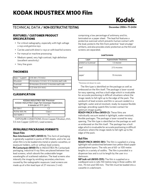
December 2006 • TI-2434TECHNICAL DATA / NON-DESTRUCTIVE TESTINGKODAK INDUSTREX M100 FilmFEATURES / CUSTOMER PRODUCT SPECIFICATIONS•For critical radiography, especially with high voltage x-rays and gamma rays •Can be used with direct x-rays or with lead foil screens •For manual or machine processing•Medium speed, very high contrast, high definition (excellent sensitivity)•Very fine grainTHICKNESSCLASSIFICATIONEXPOSURE CONDITIONS: 8 mm Copper Filtration, HVL 3.5 mm Copper (220 kV), Lead screens.AVAILABLE PACKAGING FORMATSSheet FilmNon-Interleaved (NIF) (M100-1): This form of packaging is generally supplied in packs of 100 sheets, and is for use when film is to be loaded into metal or plastic cassettes, or exposure holders, with or without lead screens.Pb Contactpak (M100-7): In INDUSTREX Pb Contactpak packaging, industrial X-ray films are placed between two lead screens, which absorb the undesirable longerwavelengths of scattered radiation. The lead screens also intensify the image by emitting secondary electrons caused by the radiographic exposure. Lead screens are made up of a thin lead layer of 27-microns (1-mil)Base / Support 0.18 mm (7.0 mils)Emulsion 25 microns (1.0 mil); 12.5 microns each side Overcoat 10 microns (0.4 mil); 5 microns each side T otal0.22 mm (8.4 mils)KODAK INDUSTREX 43IC ProcessorKODAK INDUSTREX Single Part Developer Replenisher,8 minutes at 79°F (26°C)EN-584-1C2ASTM 1815-96Class I ISO 11699-1T1comprising a low percentage of antimony and tin,laminated on a paper sheet. The lead foil features a protective overcoat which prevents human contact with the lead, protects the film from potential "lead smudge" artifacts, and also provides static protection as the film and screens are separated.Lead Screens*Thickness not drawn to scale.The film type is identified on the package as well as embossed on the film itself. The package is laser-scored for easy opening, and has a butt edge which is invaluable for accurate positioning in difficult situations where the image needs to fall right up to the edge of the pack. The sandwich of lead screens and film is vacuum sealed in a lighttight, water and oil resistant, ready-to-expose flexible package, providing superb film/screen contact for optimum image quality.READY-PACK II Film (M100-2): These films areindividually vacuum sealed in lighttight, water-resistant, flexible packages. The package is laser-scored for easy opening. The film type is identified on the package as well as embossed on the film itself. The package has a butt edge which is invaluable for accurate positioning in difficult situations where the image needs to fall right up to the edge of the pack.Roll FilmREADY-PACK (M100-381): The film is supplied in a long, lighttight roll sandwiched between two yellow-black paper polyethylene layers. The rolls are of 60- or 100-metre lengths in a variety of widths. The film is provided in a dispenser box and is cut to length by the user in a darkroom.NIF bulk roll (M100-359): The film is supplied on acardboard core in rolls 150 metres long in three widths: 60 mm, 70 mm and 100 mm. The film must be loaded into a cassette in a darkroom.LayerApproximate Thicknessprotective overcoat1.5 micron lead *27.5 micronspaper *70 micronsSAFELIGHT RECOMMENDATIONSUse a KODAK LED Safelight (660 nm red) or a red safelight filter (i.e. KODAK 1, 1A, or 2 Safelight Filter) in a suitable safelight lamp equipped with a 15-watt bulb. Keep the film at least 4 feet (1.2 metres) from the safelight.Note: Other safelight filters (i.e. KODAK 8 and GBX-2 Safelight Filter) which block radiation at 550nm and shorter wavelengths are also suitable for use.STORAGE AND HANDLINGHandle film carefully to avoid physical strains such as pressure, creasing, or buckling.It is important to realize that meeting the chemical and physical requirements does not by itself ensure thatrecords will not deteriorate. It is essential to provide proper storage conditions. ASTM E 1254 gives details of storage conditions. ISO 18911 and ISO 18902 give, for processed films, recommended storage conditions and specifications for the respective enclosure materials.Unexposed50 to 70°F (10 to 21°C), 30 to 50% RH. Properly shield from x-rays, gamma rays, or other penetrating radiation.ExposedKeep cool, dry, and properly shielded from penetrating radiation. Process as soon as possible after exposure.Processed60 to 80°F (15 to 27°C), 30 to 50% RH.RELATIVE EXPOSUREKODAK INDUSTREX Films for Various Processing ConditionsEXPOSURE CONDITIONS: 8 mm Copper Filtration, HVL 3.5 mm Copper (220 kV), Lead screens* M100 Film in 8 min 79°F (26°C) cycle is assigned a relative exposure of 1.KODAKINDUSTREX FilmsKODAK INDUSTREX Processor KODAK INDUSTREX Chemicals8 min 79°F (26°C)DR50 1.6M100* 1.0MX1250.6T2000.4AA 4000.3HS8000.15RELATIVE EXPOSURE FOR VARIOUS ENERGY LEVELSFor each exposure condition, M100 Film is assigned a relative exposure of 1.00.KODAK INDUSTREX Processor, 8 minute 79°F (26°C) cycle.* In accordance with ISO 7004 standard. Without lead screens † In accordance with ISO 7004 standard - EN 584-1 Lead screens ‡ 8 mm Copper filtration. 100/200 microns lead screens § 100/200 microns lead screensAUTOMATIC PROCESSINGNotice: Observe precautionary information on product labels and on the Material Safety Data Sheets.See Kodak publication TI-2621, Processing KODAKINDUSTREX Films , for additional information on automatic processing.EXPOSURE CONDITIONS: 200/220 kV, ISO/ANSI/EN Conditions, KODAK INDUSTREX ChemicalsFilm Characteristics (Sensitometric)* Contrast calculated between net densities of 1.5 and 3.5.Recommended Replenishment RatesThe consistency of the radiographic quality is related to the accurate adjustment of the replenishment rate.Replenishment should maintain the chemical equilibrium, replacing the components used by the film.* For optimum archivability, a 10% increase in fixer replenishment rate may bedesirable.INDUSTREXFilms ISO 120kV *EN 220kV †Iridium ‡Cobalt §DR50 2.3 1.6 1.6 1.6M100 1.0 1.0 1.0 1.0MX1250.70.60.60.6T2000.40.40.40.3AA4000.30.30.20.2HS800—0.15——KODAK INDUSTREX Processor / Cycle Base + Fog Contrast *M43IC, 8 min 79°F (26°C)0.19 5.4M43IC, 5 min 86°F (30°C)0.19 5.25M35, 10.5 min 86°F (30°C)0.194.8Solution Replenishment Volumeper 35 x 43 cm (14 x 17 inch) sheetper m 2Developer 100 mL 665 mL Fixer180 mL *1200 mLWashing and DryingWashing: Follow the processor manufacturer'srecommendation for wash flow rate, or adjust flow to achieve the equivalent of the wash tank capacity every five minutes, or twelve tank volumes per hour. Insufficient wash flow can adversely affect the life expectancy of processed radiographs. Wash flow rate should be increased if chemical spot tests or other analyticalmethods reveal a high level of retained chemicals in the processed film. For best results, the wash tank should be drained daily and left empty when not in use.Drying: Follow the processor manufacturer'srecommendation for dryer settings. In general, the dryer should be set to a temperature slightly above (3°C/5°F) the lowest temperature required to eliminate any signs of tackiness in films exiting the dryer.MANUAL PROCESSINGNotice: Observe precautionary information on product labels and on the Material Safety Data Sheets.See Kodak publication TI-2643, Guide to Manual Processing of NDT Films , for additional information on manual processing.Film Characteristics (Sensitometric)* Contrast calculated between net densities of 1.5 and 3.5.Development ConditionsBase + Fog Contrast *5 min 68° (20°C)0.19 5.03 min 75° (24°C)0.195.3DevelopmentDevelop with rack and tank, using properly replenished solutions.•Remove film and hanger 5 seconds before end of development. DO NOT ALLOW EXCESS DEVELOPER TO DRAIN BACK INTO THE TANK. Normally this will carry out the proper amount of solution to permit correct replenishment.•Use floating covers on developer tanks to reduce oxidation and evaporation; store developer replenisher in a closed container. •Fill the developer and fixer tank to its original level each morning with developer or fixer replenisher solution (topping off).•Discard solution after adding two tank volumes of replenisher to tank, or at least once a month, and refill with fresh solution.Stop, Fix, Wash and Dry StepsStop baths check development, prevent most spots or streaks, and prolong the life of the fixing bath.Immerse the film in fixer for 3 to 6 minutes , agitating for 5 seconds every 30 seconds . Film should remain in fixer for twice the time it takes to "clear" it (when the milky look disappears). Never fix film for less than 3 minutes.KODAK Hypo Clearing Agent may be used following the fixer to reduce washing time and conserve water. First rinse films in running water for 30 seconds, the use Hypo Clearing Agent for 1 to 2 minutes, followed by a final running water wash for 5 minutes.T emperature RecommendedT ime(Minutes)Agitation KODAK INDUSTREX Single Part Developer Replenisher68°F (20°C)72°F (22°C)75°F (24°C)79°F (26°C)5432Intermittent (5 seconds every 30 seconds)T emperatureRecommendedT ime Agitation KODAK Indicator Stop Bath, or acetic acid (diluted to 3.5%) solution 60 to 85°F 16 to 30°C30 to 60 secondsContinuous, ModerateKODAK Rapid Fixer, KODAK INDUSTREX Manual Fixer, or KODAKINDUSTREX LO Fixer and Replenisher 60 to 85°F 16 to 30°C3 to 6 minutes, or twice the clearing timeVigorous for 15 seconds, then intermittent (5 sec every 30 sec)Running water wash(8 volumechanges per hour)60 to 85°F 16 to 30°C 10 to 30MinutesKODAK INDUSTREX M100 FilmAerial and Industrial MarketsEASTMAN KODAK COMPANY • ROCHESTER, NY 14650-0505Revised 12-06Printed in U.S.A.KODAK INDUSTREX M100 Film KODAK Publication No. TI-2434NOTICE: While the sensitometric data in this publication are typical of production coatings, they do notrepresent standards which must be met by Kodak. Varying storage, exposure, and processing conditions will affect results. The company reserves the right to change and improve product characteristics at any time.To minimize water spots and drying marks, use KODAK PHOTO-FLO Solution after washing.Dry in a dust-free area at room temperature or in a suitable drying cabinet. Temperature not to exceed 120°F (50°C).Recommended Replenishment RatesMaintain chemical activity and solution level in the developer tank by adding 100 mL (3.38 fluid ounces) of replenisher according to instructions for each 14 x 17-inch (35 x 43 cm) film processed. Stir vigorously after each addition. Replenish the fixer tank at the rate of 180 mL (6 fluid ounces) per 35 x 43 cm (14 x 17 in) sheet of film processed.CURVESCharacteristic Curves, Manual ProcessingCharacteristic Curves, Machine ProcessingKodak, Industrex, Ready-Pack, and Photo-flo are trademarks.。
Omega Lift 竞车椅 RCOM100 产品说明书

RACING CHAIRModel RCOM100SFA CompaniesASSEMBLY BREAKDOWNM8 * 7 PCS WASHER M8 * 20MM * 3 PCS5/16" * 25MM * 4PCS1/4" * 3/4" BOLT * 6 PCS 6MM * 1 PCSSPRING WASHER * 4 PCS`BACK CUSHION * 1 PCS HANDLEBAR * 1 PCS M8 WASHER * 3PCS M8 * 20MM * 3 PCS SEAT * 1 PCS M8 WASHER * 3 PCSPLATE * 1 PCSSPRING WASHER * 4 PCS 5/16" * 25MM BOLT * 4 PCS DUST COVER * 1 PCS GAS HEIGHTADJUSTMENT * 1 PCSCHAIR LEGS * 1 PCS HANDLEBAR * 1 PCS1/4" * 3/4" BOLT * 6 PCS 12910495141167812391011121314ASSEMBLY INSTRUCTIONSAAttach the #2 left handlebar on the #4 seat, secure with screw-driver.BRepeat the same process to assemble the #3 right handlebar on the #4 seat.CAssemble #7 gas height adjustment with #6 dust cover and then insert into #5 plate.DFix the #5 plate and #4 seat sets using #9 washer and #14 spring washer with #11 bolt.EAssemble the #1 back cushion and #4 seat with bolt #10 and washer #9 x 3 pcs by #13 hex key wrench.FFix the #8 chair legs with #4 seat sets.OPERATING INSTRUCTIONSSEAT BACK INCLINATION ADJUSTMENTAThis picture shows the position of the control shaft for seat back angle adjust-ment. In normal situations, it is located at the level as the picture indicates.BPull the control shaft outward to release the seat back.CChange the seat back angle by leaning back to the desired position. Push the control shaft back in to lock the seat back in this position.DThis picture shows the locked position after seat back angle adjustment.AThis picture shows the position of the seat up/down control shaft. It is the same con-trol shaft that adjusts the seat back angle.BRaise the seat by rotating the control shaft clockwise upward without any body weight on the seat. The seat will not raise if there is body weight on it.CLower the seat by rotating the control shaft clockwise upward while seated.Release the control shaft when the desired position is achieved.A B CA B C DONE YEAR LIMITED WARRANTYFor a period of one (1) year from date of purchase, SFA Companies, Inc . will repair or replace, at its option,without charge, any of its products which fails due to a defect in material or workmanship under normal usage. This limited warranty is a consumer's exclusive remedy.Performance of any obligation under this warranty may be obtained by returning the warranted product,freight prepaid, to SFA Companies, Inc . Warranty Service Department, 10939 N. Pomona Ave., Kansas City, MO 64153.Except where such limitations and exclusions are specifically prohibited by applicable law,(1) THE CONSUMER'S SOLE AND EXCLUSIVE REMEDY SHALL BE THE REPAIR OR REPLACEMENT OF DEFECTIVE PRODUCTS AS DESCRIBED ABOVE.(2) SFA Companies, Inc. SHALL NOT BE LIABLE FOR ANYCONSEQUENTIAL OR INCIDENTAL DAMAGE OR LOSS WHATSOEVER.(3) ANY IMPLIED WARRANTIES, INCLUDING WITHOUT LIMITATION THE IMPLIED WARRANTIES OF MERCHANTABILITY AND FITNESS FOR A PARTICULAR PURPOSE, SHALL BE LIMITED TO ONE YEAR, OTHERWISE THE REPAIR, REPLACEMENT OR REFUND AS PROVIDED UNDER THIS EXPRESS LIMITED WARRANTY IS THE EXCLUSIVE REMEDY OF THE CONSUMER, AND IS PROVIDED IN LIEU OF ALL OTHER WARRANTIES, EXPRESS OR IMPLIED.(4) ANY MODIFICATION, ALTERATION, ABUSE, UNAUTHORIZED SERVICE OR ORNAMENTAL DESIGN VOIDS THIS WARRANTY AND IS NOT COVERED BY THIS WARRANTY .Some states do not allow limitations on how long an implied warranty lasts, so the above limitation may notapply to you. Some states do not allow the exclusion or limitation of incidental or consequential damages, so the above limitation or exclusion may not apply to you. This warranty gives you specific legal rights, and you may also have other rights, which vary from state to state.SFA Companies10939 N. Pomona Ave. Kansas City, MO 64153888-332-6419*******************REPLACEMENT PARTSIndividual replacement parts are not available for this product. For questions call or write: SFA Companies 10939 N. Pomona Ave. Kansas City, MO 64153, U.S.A. e-mail:*******************;Tel:(888)332-6419Fax:(816)891-6599; Website: 。
rival100参数
rival100参数
Rival100是一款令人印象深刻的游戏鼠标,它以其出色的性能和舒适的设计而闻名。
无论您是专业游戏玩家还是休闲玩家,Rival100都能为您带来无与伦比的游戏体验。
Rival100的外观设计非常吸引人。
它采用了简洁而时尚的外观,黑色的主题色调给人一种低调而高贵的感觉。
此外,鼠标的形状设计得非常符合人体工学,使您可以长时间使用而不会感到手部不适或疲劳。
Rival100的性能非常出色。
它配备了高精度的光学传感器,能够实时跟踪和响应您的每一个动作。
无论您是在进行快速射击还是精确瞄准,Rival100都能够满足您的需求。
此外,它还具有可调节的DPI设置,让您根据不同的游戏需求进行自由切换。
除了出色的性能,Rival100还具有便捷的功能。
它配备了可编程的按钮,您可以根据自己的喜好进行自定义设置。
无论是经常使用的技能还是常用的快捷键,您都可以通过Rival100轻松实现。
此外,鼠标还具有耐用的设计,能够经受长时间的使用而不会出现故障或损坏。
总的来说,Rival100是一款令人难以抗拒的游戏鼠标。
它不仅外观时尚,性能出色,而且功能丰富,让您在游戏中尽情发挥。
无论您是专业玩家还是休闲玩家,Rival100都能够满足您的需求,为您带
来极致的游戏体验。
SURFOX 305 焊接清洗系统说明书

SDS available upon request or on our website at Walter Surface Technologies Inc.810 Day Hill Rd, Windsor, CT 06095, United StatesTel: 1-866-592-5837 / Fax 1-860-298-1112June 2019The SURFOX 305 electrochemical weld cleaning system is a highly effective method of removing heat tint in the heat affected zone of welded stainless steel (TIG, Spot and MIG), without altering the surface of the parent material. It also promotes the formation of a uniform and durable chromium oxide passive layer to protect stainless steel against further corrosion. SURFOX is a safer, faster and more cost effective alternative to very hazardous pickling pastes and abrasive weld cleaning processes like wire brushing and grinding.The most powerful unit for a wide variety of jobsSURFOX 305 is an industrial, self-contained weld cleaning system with anintegrated electrolyte solution tank, a low level indicator and an automaticdispensing pump. A variable speed pump (manual or automatic) delivers thedesired amount of electrolyte solution continuously to the work piece.This system is equipped with a self-regulating inverter board, automatically monitoring and adjusting the current so as to ensure maximum cleaningeffectiveness without loss of productivity and without micro-pitting.Please read the Surfox user manual before using the unit. It can be found on Be careful when assembling the wand. Always clean & neutralize the connectors on the machine and on the wand with FT-100 or Surfox-N.The wand should only be removed for replacement purposes. Frequent assembling and disassembling of the wand can lead to poor or faulty connections.Process∙Set the machine to manual pumping or automatic feed level 1 (TIG) or level 2 (MIG) ∙Put the wand setting to the tungsten insert, brush or large graphite insert setting (under the large wand group of settings) depending on the cleaning accessory you will use. ∙Put the power to AC Level1. If needed go to AC Level 2. AC Level 3 setting should always be used with the fume elimination system to avoid overheating the cleaning accessory. ∙Ground the workpiece ∙Fill up the machine with the Surfox electrolyte solution. ∙Turn on the machine ∙Press the ON button (top button on the large wand) ∙If it is the first time, purge the machine for at least 3 minutes to get rid of the testing solution. ∙ Once the weld or the surface is cleaned, push the off button (lower button on the large wand) then use arag to remove the excess of electrolyte solution. You could also rinse with water that contains less than 200 ppm.∙ Apply Surfox-N or FT-100 everywhere the electrolyte solution has been.∙ Use a different rag to remove the Surfox-N or FT-100. You could also rinse with water that contains less than 200 ppm.∙ Wait 48 hours to make sure the passive film is formed prior applying a protector like Surfox Shine orwrapping for shipping.。
- 1、下载文档前请自行甄别文档内容的完整性,平台不提供额外的编辑、内容补充、找答案等附加服务。
- 2、"仅部分预览"的文档,不可在线预览部分如存在完整性等问题,可反馈申请退款(可完整预览的文档不适用该条件!)。
- 3、如文档侵犯您的权益,请联系客服反馈,我们会尽快为您处理(人工客服工作时间:9:00-18:30)。
《团队目标100%达成超强凝聚力3天2夜特训营》
震撼登场
你是否感觉到你的企业……
员工工作方向模糊目标匮乏借口巨多?
责任心不强敬业度不高?
员工感恩意识淡薄?
工作动力不强团队配合度弱?
结果与计划总是偏差、目标总是难以达成?
平时似乎忙忙碌碌就是没有业绩结果?
文化总是很难贯彻执行总是不能到位?
员工工作态度不积极不热情?
队伍懒散疲倦,缺乏冲劲,没有积极性
团队人员单打独斗,各自为战,难以规范
员工不认同主管,执行力差,不愿挑战高目标
企业员工玩忽职守,缺乏责任心?
基层员工整体纪律性不强?
中高管理层不能自觉主动地承担责任?
中高管理层整天机械性盲目的工作?
你是否感觉企业团队凝聚力不够?
你是否感觉企业目标总是难以达成?
参加这场震撼人心的企业目标100%达成超强凝聚力特训营
——将上述问题一一解决
中国第一家实现“教练技术”平民化的训练课程
明日领袖精英成长计划 366全员训练
中国第一个倡导企业366全员训练的培训实战课程
中国第一个拥有“定律级”自主知识产权思想体系的体验式训练课程
打造中国企业超强力团队:
1.一场世界500强广泛应用的心态及心灵训练课程
2.一场塑造积极心态、责任心和感恩心的课程
3.一场员工一起拥抱总裁,一起开心流泪的课程
4.一场以往需要付出昂贵学费才能学到,现在终于平民化的普及教练课程。
课程介绍
采用国际上盛行的心灵对话,案例模拟等情境式“教练技术”,使学员从不同层面和角度去检视自己的心态,提升自我洞察能力,发现自身的盲点与不足,增强对公司的归属感,事业的忠诚度,是一个打造无障碍沟通,责任,互信,高效,协作,付出,积极,感恩的学习型企业和以目标为导向的超强凝聚力团队的绝佳课程系统。
主要培训内容
1. 100%守诺,守信,守时;
2. 100%承担和负责任;
3. 关爱和信任;
4. 团队精神;
5. 共赢与和谐思考;
6. 开放心态与零距离沟通;
7. 选择与被迫;
8.目标实现与障碍清除;
9.创新与方法;
10.改变与突破;
11.创造一切可能100%达成目标:
培训收益
一、企业层面:
激活企业的基本元素是人,使企业团队充满活力;为企业打造通畅的沟通平台,减少沟通障碍成本;企业管理者和员工自我洞察能力得到很大的提升;团队的协作意识及团队凝聚力得到很大的加强。
吸纳优秀人才,减少优秀员工流失;使员工个人愿景与企业愿景达成一致。
快速使企业人力成本转化为人力资本。
二、员工层面:
员工愿意为企业,为自己的工作负责任;令员工心态由被动待命转变为主动进取;激励员工积极向上,获得更大的满足感。
使员工个人素质及能力得到不断提升,团队高效全面完成企业战略及目标。
课程特色
◆植根中国企业实践,秉承欧美先进教育理念:
◆企业研究专家、资深咨询师、富有实战经验的培训师,让学员体验教学过程,
关注现实案例。
◆系统培训方式:角色扮演,活动体验,小组讨论,案例,心灵对话
◆系统适合对象:企业全员,销售人员,新进员工。
培训目的作用
在这个训练里,参加者会从不同的层面和角度去检视自己的心态,加强自我洞察力,从而提升自身素质。
您会发掘企业基本的成功元素人的无限潜能,学习如何在事业和日常生活中产生和延续创造性张力,跨越障碍,缩短行为与目标的差距。
此外,您有机会亲身体验过去一切限制您个人或企业发展的固有态度和习惯,反省自己的信念和管理决策模式。
您可能会感受到被挑战,我们邀请您以开放和坦诚,积极投入的态度参与,从而调整心态,获得持续学习和改进的动力。
主要效果有:提升个人自信心发现自己的潜能发挥自己的优势
能力快速成长提升提升管理思维能力提升创新创造能力提升沟通协调能力提升工作效率提升团队协作能力理清团队目标和路向提升领导协调能力提升人际交往能力提高行动力与执行力提升快速达成目标的能力做一名优秀的高敬业度企业员工
“100%目标达成超强凝聚力”课程部分学员见证
“打造中国企业超强凝聚力团队”课程优势:1,师资力量雄厚;2,培训理念先进;3,培训方式科学高效。
一句话“棒喝截流,醍醐灌顶,心月两空”。
—玉柴机械黎辉总经理
我的企业全部员工都参加了两天两夜的特训,现在员工看到我眼神中流露出的那种感觉就象一家人一样,我的企业里处处充满着爱心,同事间也让我看到了互相帮助的团队凝聚精神,全员训练的创新训练方式,对我企业帮助真的很大!
—广东德成鞋业钟德成总经理
席教练以其敏锐的思维,幽默的语言,精辟而深入浅出的演讲博得全场热烈掌声与阵阵喝彩!课程的精心设计对企业的实质工作中出现的疑难问题作出了圆满的解决!
—广东n次方贸易有限公司谢坤佑总经理
我们的企业派了很多的伙伴到外面参加各种各样的学习很多次,但象今天席老师的团队凝聚力课程给我们带来的这种培训效果还是第一次。
—郴州市天福餐饮集团蒋朝辉总经理
“打造中国企业超强凝聚力团队”体验式教学让我们公司员工的凝聚力有了突破性飞越,同时也让我深刻明白到做人先从自己做起,这个课程实在是太厉害了。
—广东嘉华童装连锁邱美勤经理
“打造企业超强凝聚力团队”课程让我们的公司有了前所未有的变化,管理越来越容易,我们的员工学会了做人,学会了宽容,学会了沟通,学会了合作,学会了感恩……
—广东御豪集团陈总
我们全公司导入100%目标达成凝聚力课程系统并建立信念管理文化,三个月内使公司业绩增长了100%以上。
—华帝集团黄总
课程内容又深刻又容易接受,让我们真正的把激情调动起来,培训完后,我们比以前更开心,更热情,更积极了!
—广东新纪元机械公司陈祖县总经理
这是我听过所有训练课程当中最震撼的一次,谢谢席老师让我们的团队有了天翻地覆的改变
—广州柏克集团董事长叶德智
想要打造企业超强凝聚力、忠诚度团队,想让团队更敬业业、更爱业、更乐业,请赶快参加席老师的特训课程,它会让你的企业目标100%达成并有前所未有的震撼感觉!
—老板电器集团总裁任建华。