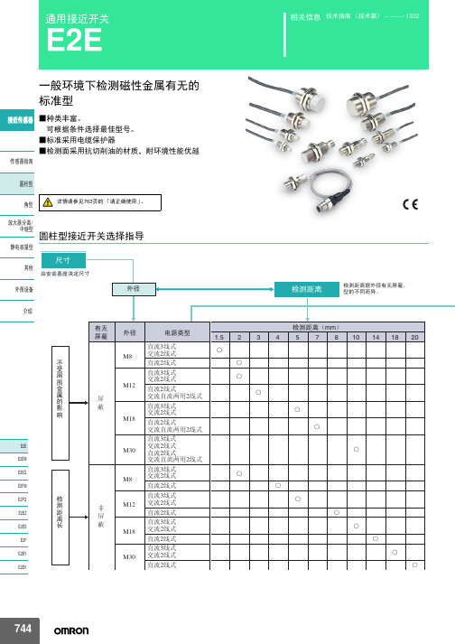
接近开关使用指南
omron E2E通用接近开关 说明书
10mm 8mm
E2E-X10D1S-M1
D
——
—
E2E-X8MD1S-M1
D
——
—
M18
14mm
E2E-X14MD1S-M1
D
——
—
M30
20mm
E2E-X20MD1S-M1
D
——
—
M8
2mm
M12
ሣ㬑
M12 3mm
E2E-X2D1-M1G
A E2E-X2D2-M1G
D
E2E-X3D1-M1G *1
㾦ൟ
ᬒ఼ߚ行 Ё㒻ൟ
M30
10mm
无
M8
4mm
䴲ሣ㬑
M12
8mm
M18
14mm
E2E-X10D1-N E2E-X4MD1 E2E-X8MD1 E2E-X14MD1
*1*2*3 *2*3 *1*2*3 *1*2*3
E2E-X10D2-N E2E-X4MD2 E2E-X8MD2 E2E-X14MD2
ሣ㬑
1.5mm
E2E-X1R5E1-M3
M8 䴲ሣ㬑
M8 2mm
E2E-X2ME1-M3
输出形态PNP NO E2E-CR8B1 E2E-X1B1 E2E-C1B1 E2E-X1R5F1 E2E-X2F1 E2E-X5F1 E2E-X10F1 E2E-X2MF1 E2E-X5MF1 E2E-X10MF1 E2E-X18MF1
Ⳉ⌕2㒓ᓣ
ƻ ƻ
Ⳉ⌕3㒓ᓣ M18 Ѹ⌕2㒓ᓣ
Ⳉ⌕2㒓ᓣ
ƻ ƻ
Ⳉ⌕3㒓ᓣ M30 Ѹ⌕2㒓ᓣ
Ⳉ⌕2㒓ᓣ
ƻ ƻ
744
E2E
⬉⑤䕧ߎ Փ⫼⦃๗
接近开关怎么用

接近开关怎么用接近开关有两线、三线之分,三线制的有PNP、NPN两种接法,分别对应相应的PLC输入点,比如源型和漏型的输入点。
接线时可以根据线的颜色区分,棕色或者红色接电源正极,蓝色接电源负极,黑色接输入信号。
一、性能特点在各类开关中,有一种对接近它物件有“感知”能力的元件——位移传感器。
利用位移传感器对接近物体的敏感特性达到控制开关通或断的目的,这就是接近开关。
当有物体移向接近开关,并接近到一定距离时,位移传感器才有“感知”,开关才会动作。
通常把这个距离叫“检出距离”。
不同的接近开关检出距离也不同。
有时被检测验物体是按一定的时间间隔,一个接一个地移向接近开关,又一个一个地离开,这样不断地重复。
不同的接近开关,对检测对象的响应能力是不同的。
这种响应特性被称为“响应频率”。
二、种类因为位移传感器可以根据不同的原理和不同的方法做成,而不同的位移传感器对物体的“感知”方法也不同,所以常见的接近开关有以下几种:1.涡流式接近开关这种开关有时也叫电感式接近开关。
它是利用导电物体在接近这个能产生电磁场接近开关时,使物体内部产生涡流。
这个涡流反作用到接近开关,使开关内部电路参数发生变化,由此识别出有无导电物体移近,进而控制开关的通或断。
这种接近开关所能检测的物体必须是导电体。
2.电容式接近开关这种开关的测量通常是构成电容器的一个极板,而另一个极板是开关的外壳。
这个外壳在测量过程中通常是接地或与设备的机壳相连接。
当有物体移向接近开关时,不论它是否为导体,由于它的接近,总要使电容的介电常数发生变化,从而使电容量发生变化,使得和测量头相连的电路状态也随之发生变化,由此便可控制开关的接通或断开。
这种接近开关检测的对象,不限于导体,可以绝缘的液体或粉状物等。
3.霍尔接近开关霍尔元件是一种磁敏元件。
利用霍尔元件做成的开关,叫做霍尔开关。
当磁性物件移近霍尔开关时,开关检测面上的霍尔元件因产生霍尔效应而使开关内部电路状态发生变化,由此识别附近有磁性物体存在,进而控制开关的通或断。
接近开关使用说明书

接近开关(无接触开关)使用说明书一、集成化接近开关是我厂根据国外技术,引进法国汤姆逊元件制造的新型集成接近开关。
产品品种规格齐全,外型结构多样,电压范围宽,重复精度高,频率响应快,抗干扰性强,使用寿命厂。
开关内腔充以树脂其全封闭,具有耐振动、耐腐蚀、防水、放油等特点。
接近开关型号及含义Proximity switch model and definition二、开关使用注意事项:使用环境温度:使用温度:-25-+70℃;储藏温度:-45-+80℃;湿度:<90%。
1、直流型开关必须用直流稳定压电源,并确保稳压电源波纹Vpp ≤10%,绝缘变压器的次级交流电源经全波整流后,用电解电容滤波(一般为470-1000uF)后的直流电源,最用用直流稳压器供电。
(特别注意:未经电容滤波不能使用)。
2、两线制开关必须先进负载再接至电源,若直接连接电源会使开关损坏。
3、开关不得超过额定技术参数使用。
4、严禁通电接线,严格按接线图上色标接线。
考虑到使用环境的影响,调整开关感应面与检测体之间的距离,一般取额定动作距离Se 的80%。
5、若有高压线和动力线通过接线开关电线附近时,为防止开关受感应误动作或损坏,请用单独金属管屏蔽。
6、直流型开关使用电感性负载时,若系统有较大干扰脉冲时,请在开关断接干扰脉冲抑制器件。
7、两线制开关一般不宜并联或串联使用,建议改用继电器串,并联使用。
8、不同材质的金属检测体对动作距离的影响:9、电容式接近开关动作距离可通过灵敏度微调电位器进行调节(切记在距离最大临界状态下使用)。
10、安求11、霍尔传感器(开关)注意磁钢(引铁石)极性S 极或N 极材料铁(A3) 不锈钢 黄铜 铅 铜 动作距离 100% 50% 40% 30% 30%8、电压输出型NPN.NO/NC。
接近开关 说明书
/接近开关使用说明书■ 接近开关● 感谢您对本公司产品的依赖,当您使用我公司产品时,请务必参阅本说明,以免因操作失误而造成不必要的损失。
●用途:适用于机床限位、检测、计数、测速、液面、自动线作定位发讯号等多种控制。
广泛应用于机械、矿山、冶金、塑料、纺织、烟草、电力、铁路、军工等部门。
● 产品型号 。
互换于本公司型号 。
接线图如图 。
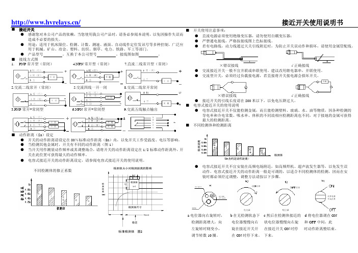
■ 接线方式图1.PNP常开型(常闭) 4.NPN常开型(常闭)7.直流二线常开型(常闭)2.交流二线常开(常闭) 5.交流四线一开一闭8.交流二线常开常闭3.PNP常开+常闭型 6.NPN常开+常闭型9.交流五线触点输出■ 动作距离(Sa)设定● 开关的动作距离请设定在80%标准动作距离(Sn)内,以免开关工作受温度、电压等影响。
● 当检测其他金属时,开关有不同的动作距离(图1)● 当开关用作测量动作频率或其调整场合,请将开关的动作距离设定在1/2标准动作距离外,开关在此位置可获得最大的动作频率。
●电容式接近开关的动作距离设定,请参阅电容式接近开关的使用说明。
检测距离(mm)标准检测体 图2检测体大小对检测距离的影响■ 开关使用注意事项:● 直流电源必须使用绝缘变压器,请勿使用自耦变压器:● 严禁通电接线,严格按接线图上色标接线。
● 若有电路线,动力线通过天关引线附近时,为防止开关误动作和损坏,请使用金属管配线。
×错误接线 √正确接线● 交流接近开关一般不宜并联或串联使用。
建议改用继电器串,并联使用。
● 交流型开关,必须经过负载接电源,若直接将开关接电源会损坏开关。
×错误接线√正确接线● 接近开关的引线长度请在200米以下,以免电压降过大。
■ 电容式接近开关的使用说明● 电容式接近开关不仅能检测金属,而且能检测塑料、玻璃、水、油等物质,因各种检测的导电率和介电常数、吸水率、体积的不同故相应检测距离也不同,对于接地的金属可获得最大的检测距离。
■ 不同检测体和检测距离检测距离检测体(Sn为约定动作距离)● 电容式接近开关不宜安装在高频电场附近,如高频焊机、超声波发生器等,以免发生误动作。
施耐德电气 电磁式接近开关 NBK-R系列 使用手册说明书

Operating InstructionsforLimit switchModel: NBK-RNBK-RMNBK-RTNBK-RANBK-R...1. Contents1.Contents (2)2.Note (3)3.Instrument Inspection (3)4.Regulation Use (4)4.1Electrical limit switch (4)5.Operating Principle (5)6.Mechanical Connection (6)7.Electrical Connection (7)missioning (8)9.Technical Information (9)10.Order Codes (10)11.Illustrations (11)12.Disposal (12)13.EU Declaration of Conformance (13)14.Type Examination Certificate (14)Manufactured and sold by:Kobold Messring GmbHNordring 22-24D-65719 HofheimTel.: +49 (0)6192-2990Fax: +49(0)6192-23398E-Mail:******************Internet: page 2 NBK-R... K09/0722NBK-R...2. NotePlease read these operating instructions before unpacking and putting the unitinto operation. Follow the instructions precisely as described herein.The instruction manuals on our website are always for currentlymanufactured version of our products. Due to technical changes, the instructionmanuals available online may not always correspond to the product version youhave purchased. If you need an instruction manual that corresponds to thepurchased product version, you can request it from us free of charge by email(******************)inPDFformat,specifyingtherelevantinvoicenumberandserial number. If you wish, the operating instructions can also be sent to you bypost in paper form against an applicable postage fee.The devices are only to be used, maintained and serviced by persons familiarwith these operating instructions and in accordance with local regulationsapplying to Health & Safety and prevention of accidents.When used in machines, the measuring unit should be used only when themachines fulfil the EC-machine guidelines.3. Instrument InspectionInstruments are inspected before shipping and sent out in perfect condition.Should damage to a device be visible, we recommend a thorough inspection ofthe delivery packaging. In case of damage, please inform your parcel service /forwarding agent immediately, since they are responsible for damages duringtransit.Scope of delivery:The standard delivery includes:•Electrical Limit Switches Model: NBK-R, NBK-RM, NBK-RT or NBK-RANBK-R... K09/0722 page 3NBK-R...page 4 NBK-R... K09/07224. Regulation UseAny use of the device which exceeds the manufacturer’s specification may invalidate its warranty. Therefore, any resulting damage is not the responsibility of the manufacturer. The user assumes all risk for such usage.The Limit Switches for the NBK Bypass Level Indicators are used for continuos measuring, display and monitoring of liquids in tanks or vessels. Depending on the design the limit switches are suitable for applications with a higher operating temperature or for the use in hazardous areas.4.1 Electrical limit switch- For standard applications NBK-R/NBK-RM: Bistable changeover contact fitted ina polycarbonate housing with 3m connection cable- For high temperature applications NBK-RT200/-RT400: Bistable changeovercontact fitted in an aluminium die cast housing with terminal connectors.- For ATEX applications NBK-RA: Bistable changeover contact as anencapsulated proximity switch fitted in metallic cast housing with 3 m connection cable.ATEX-marking for contact NBK-RA (encapsulated version): II 2G Ex mb IIC T6 / T5 Gb II 2D Ex mb IIIC IP67 T 105 °C Db→ Use the contacts appropriate and as intended.→ Make sure that only accessories are used in hazardous areas that meetall the requirements of the European directives and national legislation.The contacts NBK-RA with ATEX approval meet the requirements of category2 GD. The proximity switches with ATEX approval are used in the following zones:→ 2G in zone 1 → 3G in zone 2 → 2D in zone 21 → 3D in zone 22NBK-R...5. Operating PrincipleKobold Bypass Limit Transmitter are used for the monitoring of limit values intanks or vessels.They are firmly attached with mounting plates and ribbon clamps to the BypassLevel Indicator, model NBK, and can be moved to any position on the bypass-tube within the measuring length.The reed-contacts in the limit switches react bistable and they are switched bythe magnetic float inside the NBK tube as passing by.One or more limit switches can be mounted on the bypass.NBK-R... K09/0722 page 5NBK-R...page 6 NBK-R... K09/07226. Mechanical ConnectionNBK-R/NBK-RMMount and tighten the reed switch (NBK-R, NBK-RM and NBK-RA) - if available - on the bypass tube at the opposite side of the roller indicator with the provided ribbon clamps (ex contact: two ribbon clamps). The height of the switch contacts may be selected at will. The cable connection must point downwards. The switch must be attached close to the bypass tube. Due to technical adaptations, it may come to malfunctions, when installing new contacts in an existing plant. If the contact does not switch during the float passes by, the preassembled spacer (plastic) must be removed.NBK-RANBK-RT200/400The high temperature switch RT200/400 will be mounted to the bypass tube with the tube clip fixed at the contact housing.Thermal screeningNBK-R...NBK-R... K09/0722page 7ATEX- contactbrown blueblack 7. Electrical ConnectionLimit switch NBK-R, NBK-RM, NBK-RT, NBK-RAAttention!Observe the allowed electrical ratings for the limit switch.Maximum values NBK-RNBK-RM Standard- contact NBK-RT Hightemperature contact NBK-RAATEX-contactSwitching capacity: 60 W/VA 80 VA 45 W/VA Switching current: 1 A 1 A 0,6 A Switching voltage:230 V AC/DC250 V AC/DC230 V AC/DCInstall the switch (if available) according to the diagram and connect it to the electrical controller.When switching inductive loads, such as contactors, relays, etc., electrical limit values should not be exceeded, also temporarily by e.g. voltage peaks. The use of a contact protection relay is recommended to avoid overloading the reed contacts.Valid regulations for hazardous areas, and regulations for installation (DIN/VDE 0165), should be observed when installing the NBK level indicator in zone 1 or 2 of hazardous areas (no combustible liquids).Note to NBK-RA:Protect the circuit of the limit contact with a fuse. This fuse must tolerate the permitted nominal current of the switching contact and must have a deactivating ability according to the possible short circuit current of the power system at the place of installation. The contact is activated by the North Pole of a magnet and deactivated by its South Pole.NBK-RANBK-RTNBK-R NBK-RMNBK-R...page 8 NBK-R... K09/07228. CommissioningCommissioning of the electrical reed switchFunction of switchesAll switches have three connection poles (black (2), blue (3) and brown (1)).The black wire (2) is the common pole for both switching functions (N/C and N/O contact).The float must pass the switch once in both directions so that the switching func-tion is in line with the terminal connection diagram and table below.These instructions are often ignored when an alarm lamp is connected directly with the result that the alarm lamp incorrectly indicates a fault.When the switch has been passed, it is ready for operation and requires no maintenance.black (2) / blue (1) black (2) / brown (3) float above open closed float below closed openHysteresisHysteresis is the difference between contact closing and opening points. A hysteresis of approximately 15 mm float travel is achieved by factory tuning of the float magnet and contact strength.NBK-R...NBK-R... K09/0722 page 99. Technical InformationLimit contacts, model NBK-R/NBK-RM Contact operation: bistable changeover contact Switching hysteresis: approximately 15 mm Max. switching capacity: 60 W/VA; 230 V AC/DC ; 1 A Contact resistance: 100 m Ω Medium temperature: max. 100 °C Ambient temperature: max. 75 °C Connection: 3 m PVC cable Housing: polycarbonate Protection: IP 67Limit contacts, model, NBK-RT200/-RT400 Contact operation: bistable changeover contact Switching hysteresis: approximately 15 mm Max. switching capacity: 80 VA; 250 V; 1 A Contact resistance: <20 m Ω Medium temperature: max. 200 °C (-RT200) / 400 °C (-RT 400) Ambient temperature: 145 °C (RT200) / 350 °C (-RT400) Connection: terminal connectors, screwed cable gland Housing: aluminium die cast housing, terminal connectors Protection: IP 65ATEX limit switch, model NBK-RA Contact operation: bistable changeover contact encapsulated Switching hysteresis: approximately 15 mm Max. switching capacity: 45 VA, 230 V AC/DC , 0,6 A Temperature class: T6 / T5 Max. medium temperature: 70 °C / 85 °C Connection: 3 m PVC cable Housing: metallic, cast (GD-ZN Al 4 Cu1) Protection:ATEX-marking: II 2G Ex mb IIC T6/T5 Gb II 2D Ex mb IIIC IP67 T 105 °C DbNBK-R...page 10 NBK-R... K09/072210. Order CodesNBK-R NBK-RMStandard limit contact (bistable changeover contact)NBK-RT200High temperature limit contact, t max 200 °CNBK-RT400High temperature limit contact, t max 400 °C11. IllustrationsNBK-R/NBK-RM NBK-RT NBK-RA12. DisposalNote!•Avoid environmental damage caused by media-contaminated parts•Dispose of the device and packaging in an environmentally friendly manner•Comply with applicable national and international disposal regulations and environmental regulations.BatteriesBatteries containing pollutants are marked with a sign consisting of a crossed-out garbage can and the chemical symbol (Cd, Hg, Li or Pb) of the heavy metal that is decisive for the classification as containing pollutants:Cd1 Hg2 Pb3 Li41. …Cd" stands for cadmium2. …Hg" stands for mercury3. …Pb" stands for lead4. …Li" stands for lithiumElectrical and electronic equipment13. EU Declaration of ConformanceWe, KOBOLD Messring GmbH, Hofheim-Ts, Germany, declare under our sole responsibility that the product:Limit Contact model: NBK-R / NBK-RM / NBK-RTto which this declaration relates is in conformity with the standards noted below: DIN EN 61010-1: 2010Safety requirements for electrical measuring, control and laboratory instruments EN 60529:2014Protection type through case (IP code)Also, the following EEC guidelines are fulfilled:2014/35/EU Low Voltage Directive2011/65/EU RoHSFurthermore, we declare that the productmodel: NBK-RA (ELOBAU 610*)to which this declaration relates is in conformity with the standards noted below: EN 60079-0:2012 General RequirementsEN 60079-18:2009 Equipment protection by encapsulation ‘m’EN 60079-26:2007 Equipment with equipment protection level (EPL) GaEC type examination test BVS 03 ATEX E 126 Xalso, the following EEC guidelines are fulfilled:2014/34/EU ATEXHofheim, 09 March 2021H. Peters M. WenzelGeneral Manager Proxy Holder14. Type Examination Certificate。
欧姆龙接近开关说明书
Ẕ⌟⠽ԧⱘ䖍䭓d(mm)
E2K-X8M
䎱 行 10 X嗻 嗼 mm 8
ƶ50 t
X 6
4
2
0
5
10
ഄ䞥ሲ
䴲ഄ䞥ሲ ⦏⩗ 㣃䜮˄ᷥ㛖˅
ϭ⛃䝌˄ᷥ㛖˅
15
20
25
Ẕ⌟⠽ԧⱘ䖍䭓t(mm)
E2K-X15M
䎱 行 25 X嗻 嗼 mm 20
ƶd t=3mm
X
15
10
5
ഄ䞥ሲ
䴲ഄ䞥ሲ
⦏⩗ 㣃䜮˄ᷥ㛖˅ ϭ⛃䝌˄ᷥ㛖˅
1
E2K-C
⦏⩗ 㣃䜮˄ᷥ㛖˅
E2K-X E2K-F
0
5
10
15
20
25
Ẕ⌟⠽ԧⱘ䖍䭓t(mm)
E2K-L
E2KQ-X
E2J
E2K-X8M
䎱 行 10
X嗻 嗼 mm
8
ƶd t=3mm
X
ഄ䞥ሲ
6 䴲ഄ䞥ሲ
4
⦏⩗ 2
㣃䜮˄ᷥ㛖˅
ϭ⛃䝌˄ᷥ㛖˅
0
10 20 30 40 50 60 70
圆柱型
E2K-X
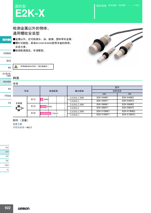
检测金属以外的物体。 通用螺纹安装型
䖥Ӵᛳ఼ ■金属以外,还可检测水、油、玻璃、塑料等非金属。 ■螺钉切割型。具有M12/M18/M30型等丰富的种类。 安装方便。 ■检测距离固定,非调整型。
Ӵᛳ఼ᣛफ
᷅ൟ
详情请参阅926页的 「请正确使用」。
㾦ൟ
ᬒ఼ߚ行
Ё㒻ൟ 种类
䴭⬉ᆍ䞣ൟ 本体
ˆ2. Eൟ˖Ẕ⌟ᰒ冫♃˄㑶˅ Yൟ˖ࡼᰒ冫♃˄㑶˅
䖥Ӵᛳ఼
Ӵᛳ఼ᣛफ ᷅ൟ 㾦ൟ ᬒ఼ߚ行 Ё㒻ൟ 䴭⬉ᆍ䞣ൟ ݊Ҫ ೈ䆒 ҟ㒡
接近开关正确的使用方法
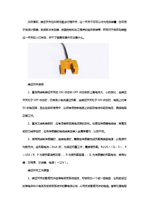
众所周知,接近开关也叫做无触点行程开关,这一开关不仅可以作为检测装置,也可用于变频计数器、变频脉冲发生器、液面控制和加工程序的自动衔接等,然而对于很多刚接触这一开关的人们来说,并不了解具体操作方法是什么。
接近开关使用:1、直流两线制接近开关的ON状态和OFF状态实际上是电流大、小的变化,当接近开关处于OFF状态时,仍有很小电流通过负载,当接近开关处于ON状态时,电路上约有5V的电压降,因此在实际使用中,必须考虑控制电路上的驱动电流和驱动电压,确保电路正常工作。
2、直流三线制串联时,应考虑串联后其电压降的总和。
如果在传感器电缆线,有高压或动力线存在时,应将传感器的电缆线单独装入金属导管内,以防干扰。
3、使用两线制传感器时,连接电源时,需确定传感器先经负载再接至电源,以免损坏内部元件。
当负载电流<3mA时,为保证可靠工作,需接假负载。
R≤US/(IL-3)、P >US2/R、P为假负载消耗功率;、R为假负载阻值;、IL为传感器的负载电流、使用仪器:万用表、示波器、电源(+12V)。
接近开关工作原理:1、接近开关的敏感元件由导电极板系统组成,可被视为一个或一组电容,出现或经过的导电体和介电体改变极板系统中的静电场分布,从而改变敏感元件的电容。
信号处理电路检测出这种变化,就可以检测出目标物体的接近。
2、相比之下,传感器的结构较为简单、工作阻抗高,因而功耗较低,此外通过锁频或频谱扩展载波调制技术,可以使之不受寄生或有意的干扰影响。
其他方案则很难达到设计者的要求。
3、机械开关的稳定性和可靠性较差磁敏感方式功耗过大,也容易受外磁场的影响;光学式和超声式传感器的结构较为复杂,容易受外界干扰。
以上就是相关内容的介绍,希望对大家了解这一问题会有更多的帮助,同时如有这方面的兴趣或需要,可以咨询了解一下南京凯基特电气有限公司。
霍尔接近开关使用说明书
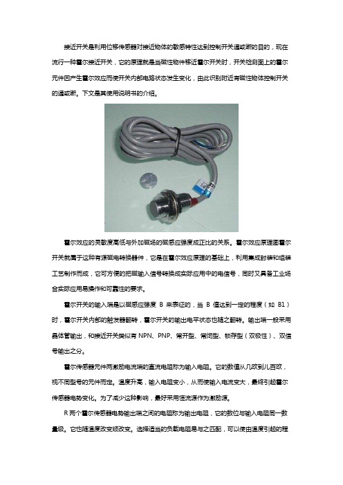
接近开关是利用位移传感器对接近物体的敏感特性达到控制开关通或断的目的,现在流行一种霍尔接近开关,它的原理就是当磁性物件移近霍尔开关时,开关检测面上的霍尔元件因产生霍尔效应而使开关内部电路状态发生变化,由此识别附近有磁性物体控制开关的通或断。
下文是其使用说明书的介绍。
霍尔效应的灵敏度高低与外加磁场的磁感应强度成正比的关系。
霍尔效应原理图霍尔开关就属于这种有源磁电转换器件,它是在霍尔效应原理的基础上,利用集成封装和组装工艺制作而成,它可方便的把磁输入信号转换成实际应用中的电信号,同时又具备工业场合实际应用易操作和可靠性的要求。
霍尔开关的输入端是以磁感应强度B来表征的,当B值达到一定的程度(如B1)时,霍尔开关内部的触发器翻转,霍尔开关的输出电平状态也随之翻转。
输出端一般采用晶体管输出,和接近开关类似有NPN、PNP、常开型、常闭型、锁存型(双极性)、双信号输出之分。
霍尔传感器元件两激励电流端的直流电阻称为输入电阻。
它的数值从几欧到儿百欧,视不同型号的元件而定。
温度升高,输入电阻变小,从而使输入电流变大,最终引起霍尔传感器电势变化。
为了减少这种影响,最好采用恒流源作为激励源。
R两个霍尔传感器电势输出端之间的电阻称为输出电阻,它的数位与输入电阻同一数量级。
它也随温度改变顺改变。
选择适当的负载电阻易与之匹配,可以使由温度引起的程水电势的漂移减至最小。
由于霍尔传感器电势随激励电流的增大而增大,故在应用中总希望选用较大的激励电流1M但激励电流增大,程尔元件的功耗增大,元件的温皮升高,从而引起霍尔传感器屯势的温漂增大,因此每种型号的几件均规定了相应的最大激励电流,它的数值从几毫安至几百毫安。
灵敏度KH=EH/IB,它的数值约为\10MV(MA.T)左右。
(5)最大磁感应强度BM---霍尔传感器参数磁感应强度超过BM时,霍尔传感器电势的非线性误差将明显增大,特斯捡(T)成几千高斯(Gs)(1Gs=104T)。
6M的数值一般为零点刀霍尔传感器输出端之间的开路电压称为不等位电势,使用时多采用电桥法来补偿不等位电势引起日在一定磁感应强度和激励电流的作用下,温度每变化1摄氏度时,霍尔传感器电势变化的百分数弱为霍尔传感器电势温度系数,它与霍尔传感器元件的材料有关。
- 1、下载文档前请自行甄别文档内容的完整性,平台不提供额外的编辑、内容补充、找答案等附加服务。
- 2、"仅部分预览"的文档,不可在线预览部分如存在完整性等问题,可反馈申请退款(可完整预览的文档不适用该条件!)。
- 3、如文档侵犯您的权益,请联系客服反馈,我们会尽快为您处理(人工客服工作时间:9:00-18:30)。
接近开关使用指南
一:规格参数
品牌RIKO/瑞科反应频率25HZ CE加工定制
【型号】:SN04-N (NPN NO常开)
SN04-P (PNP NO常开)
【外形】:方形18*18*36mm
【线长】:1.5M
【检测距离】:4mm
【响应时间】:2ms to 50ms
【迟滞距离】:≤10%检测距离
【检测物体】:金属(铜、铁、铝、金等)
【输出电压】:10-30VDC
【输出电流】:300MA
【外壳材料】:塑料ABS
二:原理及相关使用
1.额定电压:10~30V
2.需搭配福誉模组使用
3.使用原理:本接近开关为电感式接近开关,用来检测金属物体。
当接近开关前端检测到
金属物体时,接近开关触发,灯亮且信号线释放反向电平。
4.关于NPN和PNP型的接近开关的使用区别:
NPN型:有效(触发)时信号线释放低电平
PNP型:有效(触发)时信号线释放高电平
因此在搭配我们的控制器,即无论是单轴控制器还是三轴控制器(都是低电平有效),都请配NPN型的接近开关。
5.接线:
黑色:信号线
棕色:+24V
蓝色: 0V
注:具体接线请根据实际情况,搭配我们的控制器请按照相关控制器使用指南。
三:搭配控制器的使用说明
1.搭配我们的单轴DKC控制器使用时:
按照DKC使用指南正确将两个接近开关接入并安装到模组上的两个不同的位置时,此时接近开关仅起到限制行程的作用。
因此DKC-1B控制器控制的每根轴上两端都应该有一个接近开关,用来进行往复运动时起到限位的作用。
使用注意:
由于电感式接近开关的感应距离短,安装限位器时请尽量缩短与检测金属物体(滑台或拖板)的距离,当且仅当接近开关检测到金属物体时,接近开关触发,灯亮,信号线释放反向电平。
2.搭配我们的4030三轴控制器使用时:
按照AMC4030使用指南正确将接近开关接入并安装到模组上的任意位置时,此时接近开关仅起到提供原点位置的作用。
因此AMC4030控制器控制的每根方向轴上都应该有一个接近开关,用来提供原点位置及给软件获取相对位置的作用。
还因此4030控制器上的接近开关功能除了给软件提供一个原点,还能用来完成回零的作用。
(因此:并没有限制行程的作用)
使用注意:
由于电感式接近开关的感应距离短,安装限位器时请尽量缩短与检测金属物体(滑台或拖板)的距离,当且仅当接近开关检测到金属物体时,接近开关触发,灯亮,信号线释放反向电平。
问题解答:那我如何用4030控制器实现模组的限位?
1.自己编写程序,利用运行位置限位
2.也可以将接近开关的信号线接到IN口(控制器输入口),还是要利用程序(流程控制-
开启输入中断)实现
三:接近开关在模组上的安装说明
40直线和80直线的安装样图80皮带和120直线的安装样图。