工作台说明书
蒙特苏马工作台说明书

OWNER'S MANUAL 4' ADJUSTABLE HEIGHT STEEL WORKBENCH WITH PEGBOARD BACK WALLMWB482454B LIFE ORGANIZEDMontezuma is committed to helping you succeed in both your workand personal life by being organized, prepared and equipped withthe right tools, gear and home supplies at your finger tips.Keep your life organized with Montezuma.Thank you for your purchase of this Montezuma Workbench.ATTENTIONTO REDUCE THE RISK OF INJURY, THE USER MUST READ ANDUNDERSTAND THIS INSTRUCTION MANUAL BEFORE USING THIS PRODUCT FOR THE FIRST TIME. SAVE THESE INSTRUCTIONS FOR FUTURE REFERENCE.Fill in the following information and retainthis owner's manual for future reference:MODEL(S):DATE OF PURCHASE:PLACE OF PURCHASE:RECEIPT NO:2SPECIFICATIONSMAXIMUM PRODUCT WEIGHT: 1000 lb (450 kg) of static, evenly distributed weight MAXIMUM SHELF WEIGHT: 50 lb (22.7 kg)MAXIMUM WEIGHT ON PEGBOARDS: 35 lb (15.9 kg)OVERALL DIMENSIONS:48" W x 24" D x 66.2" H (121.9 cm W x 61 cm D x 168.1 cm H)WORKBENCH DIMENSIONS:48" W x 24" D x 41" H (121.9 cm W x 61 cm D x 104 cm H)Steel frame height adjusts from 29" to 41" in 1" increments4PARTS LISTToorderreplacementparts,*****************************************************(Monday–Friday, 8:00 am–4:30 pm, CST). Have the part number and quantity ready. Replacement keys may be ordered using the code that appears on the face of the lock. Not all parts are covered under warranty. Those parts not covered can be purchased.REF DESCRIPTIONPART NUMBER QTY 1M5 x 18 mm Lag Screw 122327292M6 Hex Nut 122329693M6 x 10 mm Bolt 122328694Leveling Feet 12232645Montezuma Nameplate 1217011213545M6 Hex Nut For use with the bolts Leveling Feet For leveling the workbench M5 x 18 mm Lag ScrewUse to attach work top to frame M6 x 10 mm BoltFor frame assembly Montezuma NameplateFor attaching to the front of theworkbench29694691ASSEMBLYInstall one of the leveling feet at the bottom of each adjustable leg section.Slide each adjustable leg section onto a main leg section until you reach the desired height. Remember that the wood work top is 1.25" thick, so you will need to reduce the leg length by the 1.25" to hit your targeted height. Make sure the length of each leg is the same.Insert one cross brace so that it can be fastened together with the adjustable leg section and main leg section at the desired height, making sure all holes are lined up. Use four (4) nuts and bolts to secure the cross brace. Repeat to connect a second leg, which creates one leg assembly.Secure the leg assembly with another cross brace at the top of the legs using four (4) bolts and nuts per leg.Tighten all nuts and bolts.Repeat to create the second leg assembly, which will form the other end of the workbench.Line up the holes in the two cross bars with the holes in the top of the leg assemblies. The cross bar flange will overlap the legs at each end. Secure each cross bar to the top of each leg using two (2) nuts and bolts.Connect the braces from the front cross bar to the leg assemblies to improve stability, using two (2) nuts and bolts for each brace.Do not tighten fasteners until all legs are connected to the cross bars and braces. Once all legs are connected, use a level to make sure the frame is straight, then tighten all nuts and bolts.Attach the bottom shelf to the bottom cross braces using two (2) nuts and bolts on either side. The shelf is recessed so that a stool can be tucked under the workbench.Place the work top on a soft mat with the finished top surface facing down.Place the steel frame upside down on the work top. The work top should be flush with the back of the frame – this would be the back of your workbench. It will allow the workbench to be pushed close to the wall and leave an overhang on the front of the workbench.Center the frame, right to left.Mark the holes on the steel frame onto the bottom of the work top. Remove the steelframe. Drill pilot holds in the bottom of the work top at the locations you have marked.Place the steel frame back on the work top and secure using the screws that areincluded. Six screws are used to attach the work top to each long cross bar and four screws are used to attach the work top to each short cross brace.Turn the workbench upright and place in the location it will be used. Check to make sure the workbench is still level. If you need to adjust, use the leveling feet.Attach the Montezuma Nameplate to the right hand side of the front cross bar using the self-adhesive backing.8Build the back wall onto the workbench by slipping a column onto one back corner of the work top. The column should be nested above and below the work top. Mark the location of the holes in the bottom of the column on the bottom of the work top. Remove the column and drill pilot holes in the bottom of the work top. Set the column back in place so the work top is nested into the column and secure the column in place using the four (4) lag screws. Repeat on the other side with the remaining column.Attach the top shelf by nesting it down in the tops of each of the columns. The columns have been designed with notches to help locate the top shelf into place. Fasten the top shelf to each of the columns using two (2) nuts and bolts in the side and back of the columns.Place the column cross brace under the top shelf and secure it to each column with one (1) nut and bolt. The cross brace is notched so it will set under the top shelf and the end of the cross brace will overlap the front of each column.On the back side of the workbench, lift the pegboard panel into place. Line up the holes of the pegboard panel with the holes in the inside edge of the columns. Secure with three (3) nuts and bolts. It may be easier to complete this step with one person inserting the bolts into the holes from the front and another person in back tightening the nut. Secure the top of the pegboard panel to the top shelf with two (2) nuts and bolts. Repeat this assembly with the other side of the pegboard panel.Carefully drill pilot holes in the top of the work top that line up with the holes in the bottom of the pegboard panel. Screw the bottom of the pegboard panel into place using lag screws. Check one more time to make sure your workbench and back wall are level. Secure all fasteners and move into place. Make sure it is level in the area it will be used.MAINTENANCEPeriodically tighten all hardware and make sure workbench is level.Clean the work top with wood cleaner.SAFETYDO NOT let children play or hang on the edge of the workbench. It could tip and cause personal injury or product damage.DO NOT stand or lean on the work top. The workbench could tip and cause personal injury or product damage.DO NOT mount this product on a truck bed or any other moving object. This may cause personal injury or product damage.DO NOT alter this project in any manner. For example, do not weld external lockbars or attach electrical equipment. This may cause product damage or personal injury.Keep the product on level surfaces. The product may become unstable and tip if stored or moved on an uneven surface, which may cause personal injury or product damage.Do not place items so that they overhang the top or bottom shelves. Items could fall and cause personal injury or product damage.Do not place items that have a combined weight of over 50 lb (22.7 kg) on either of the shelves. Excess weight could result in personal injury or product damage.Do not hang items that have a combined weight of more than 35 lb (15.9 kg) on the steel pegboard panel. Excess weight could result in personal injury or product damage.MAXIMUM PRODUCT WEIGHT: 1000 lb (450 kg) of static, evenly distributed weight WARNINGCancer and Reproductive Harm – 103This product is warranted to be free from defects in materialsand workmanship for a period of one (1) year from the dateof original purchase.Ifthisproductisdefective,*********************************or call 1-800-459-4409 (Monday–Friday, 8:00 am–4:30 pm, CST). If the product is defective, we will replace the defective part at no cost to you.Please do not ship your product back to the store or to usunless we send you written instructions for return.In the event it becomes necessary for your productto be returned, we will notify you how to proceed.A copy of your original purchase receipt must accompanythe returned product.11****************************FORM#: MWB482454B-01/20。
超净工作台说明书

产品说明书超净工作台的优点是操作方便自如,比较舒适,工作效率高,预备时间短,开机30分钟以上即可操作,基本上可随时使用。
在工厂化生产中,接种工作量很大,需要经常长久地工作时,超净台是很理想的设备。
超净工作台由三相电机作鼓风动力,功率145~260W左右,将空气通过由特制的微孔泡沫塑料片层叠合组成的“超级滤清器”后吹送出来,形成连续不断的无尘无菌的超净空气层流,即所谓“高效的特殊空气”,它除去了大于0.3μm的尘埃、真菌和细菌孢子等等。
超净空气的流速为24~30m/min,这已足够防止附近空气可能袭扰而引起的污染,这样的流速也不会妨碍采用酒精灯或本生灯对器械等的灼烧消毒。
工作人员就在这样的无菌条件下操作,保持无菌材料在转移接种过程中不受污染。
但是万一操作中途遇到停电,暴露在未过滤空气中的材料便难以幸免污染。
这时应迅速结束工作,并在瓶上作出记号,内中的材料如处于增殖阶段,则以后不再用作增殖而转入生根培养。
如为一般性生产材料,因极其丰富也可弃去。
如处于生根过程,则可留待以后种植用。
超净台电源多采用三相四线制,其中有一零线,连通机器外壳,应接牢在地线上,另外三线都是相线,工作电压是380V。
三线接入电路中有一定的顺序,如线头接错了,风机会反转,这时声音正常或稍不正常,超净台正面无风(可用酒精灯火焰观察动静,不宜久试),应及时切断电源,只要将其中任何两相的线头交换一下位置再接上,就可解决。
三相线如只接入两相,或三相中有一相接触不良,则机器声音很不正常,应立即切断电源仔细检修,否则会烧毁电机。
这些常识应在开始使用超净台时就向工作人员讲解清楚,免除不应造成的事故与损失。
超净工作台进风口在背面或正面的下方,金属网罩内有一普通泡沫塑料片或无纺布,用以阻拦大颗粒尘埃,应常检查、拆洗,如发现泡沫塑料老化,要及时更换。
除进风口以外,如有漏气孔隙,应当堵严,如贴胶布,塞棉花,贴胶水纸等。
工作台正面的金属网罩内是超级滤清器,超级滤清器也可更换,如因使用年久,尘粒堵塞,风速减小,不能保证无菌操作时,则可换上新的。
X-Y数控工作台设计说明书(最终版)

高、动态响应快、运转平稳、寿命长、效率高,预紧后可消除反向间隙。
(3)减速装置的选用
选择了步进电动机和滚珠丝杠副以后,为了圆整脉冲当量,放大电动机的输出转矩,降低运动部件
折算到电动机转轴上的转动惯量,可能需要减速装置,且应有消间隙机构。为此,本设计决定采用无间
2.2控制系统的设计.................................................................3
2.3绘制系统组成框图...............................................................3
2.4绘制机械传动系统简图...........................................................3
3、机械传动部件的计算与选型...........................................................4
3.1脉冲当量的确定.................................................................4
伺服系统实现位置伺服控制有开环、闭环、半闭环3种控制方式。开环控制的伺服系统存在着控制
精度不能达到较高水平的基本问题,但是步进电机具有角位移与输入脉冲的严格对应关系,使步距误差
不会积累;转速和输入脉冲频率严格的对应关系,而且在负载能力范围内不受电流、电压、负载大小、
环境条件的波动而变化的特点。并且步进电机控制的开环系统由于不存在位置检测与反馈控制的问题,
X、Y工作台设计说明书解读

目录一、课程设计目的 (2)二、课程设计任务及内容 (2)三、总体方案的确定 (3)1、机械传动部件的选择 (3)2、控制系统设计 (4)四、机械传动部件的计算与选型 (4)1、导轨上移动部件的重量估算 (4)2、铣削力的计算 (4)3、直线滚动导轨副的计算与选型 (6)4、滚珠丝杠螺母副的计算与选型 (8)5、步进电机减速箱的选用 (11)6、步进电动机的计算与选型 (12)7、增量式旋转编码器的选用 (16)五、工作台机械装配图的绘制 (16)六、工作台控制系统电路图绘制 (16)七、步进电动机驱动电源的选择 (16)总结 (17)参考文献 (18)附录: (19)1、操作控制面板 (19)2、控制程序 (19)X-Y数控工作台机电系统设计X-Y数控工作台是许多机电一体化设备的基本部件,如数控车床的纵-横向进刀机构、数控铣床和数控钻床的X-Y工作台、激光加工设备的工作台、电子元件表面贴装设备等。
因此,选择X-Y数控工作台作为机电综合课程设计的内容,对于机电一体化专业的教学具有普遍的意义。
模块化的X-Y数控工作台,通常有导轨座、移动滑块、工作平台、滚珠丝杠螺母副,以及伺服电动机等部件构成。
其外观形式如图1所示。
其中,伺服电动机作为执行元件用来驱动滚珠丝杠,滚珠丝杆的螺母带动滑块和工作平台在导轨上运动,完成工作台在X、Y方向的直线移动。
导轨副、滚珠丝杆的螺母副和伺服电动机等均已标准化,由专门厂家生产,设计时只需根据工作载荷选取即可。
控制系统根据需要,可以选用标准的工业控制计算机,也可以设计专用的微机控制系统。
图1 X-Y数控工作台外形一、课程设计目的机电一体化技术又称为机械电子技术,它不是一门独立的工程学科,是机械技术、电子技术、信息技术、自动控制技术等相关技术综合。
机电一体化课程设计是针对机电一体化系列课程的要求,继机电一体化课程后的一门设计实践性课程。
它是理论与实践的结合,是培养学生机电一体化产品综合设计能力必不可少的教学环节。
X-Y双坐标联动数控工作台课程设计说明书

目录1。
课程设计目的 (1)2。
课程设计任务 (1)2.1设计题目: (1)2。
2技术数据 (1)2。
3技术要求 (1)3。
总体结构设计 (1)3.1滚珠丝杠设计 (2)3.2滚珠丝杠副的选取 (3)3。
3稳定性运算 (4)3。
4压杆稳定性计算 (5)4.滚动导轨 (6)4。
1计算行程长度寿命 Ts (6)4。
2计算动载荷 (6)5。
步进电机的选择 (8)5.1步距角的确定 (9)5.2步进电机转矩校核 (10)5.3频率校核 (12)6.总结 (12)7。
参考文献 (13)1。
课程设计目的本课程设计的目的在于培养学生对典型机电一体化产品机械结构的设计能力和对机电伺服系统的设计能力,在学习有关专业课程设计的基础上,进行机电系统设计的初等训练,掌握手册、标准、规范等资料的使用方法,培养分析问题和解决问题的能力,为以后的毕业设计打下良好的基础.2.课程设计任务2。
1设计题目:X—Y双坐标联动数控工作台设计2。
2技术数据工作台长×宽(mm):450×310工作台重量(N):3300行程(mm):ΔX=60-100;ΔY=50-100脉冲当量:0。
05-0。
08mm/p2。
3技术要求(1)工作台进给运动采用滚珠丝杠螺旋结构(2)滚珠丝杠支撑方式:双锥-简支型(3)驱动电机为反应式步进电机(4)步进电机与滚珠丝杠间采用齿轮降速要求消除齿轮间隙3.总体结构设计数控工作台采用由步进电机驱动的开环控制结构,其单向驱动系统结构简图如图所示:实际设计的工作台为X、Y双坐标联动工作台,工作台是由上拖板、中拖板、下拖板及导轨、滚珠丝杠等组成.其中下拖板与床身固联,它上面固定X向导轨,中拖板在下拖板的导轨上横向运动,其上固定Y向导轨,上拖板与工作台固联,在Y向导轨上移动。
X、Y导轨方向互相垂直。
3。
1滚珠丝杠设计滚珠螺旋传动按滚动体循环方式分为外循环和内循环两类,其中应用较广的是插管式和螺旋槽式,它们各有特点,其轴向间隙的调整方法主要有垫片调隙式和螺纹调隙式。
一维工作台设计说明书

电子精密机械设计课程设计一维伺服移动工作台设计说明书(仅供参考)目录课程设计任务2设计任务介绍2设计内容2 一、分析工作条件和设计要求 3 二、电机选型3三、滚珠丝杠的选型4四、联轴器的选型9五、转矩讨论10六、电机的校核12七、联轴器校核13八、导轨选型13九、轴承的校核14十、轴承的校核18十一、系统谐振频率计算18十二、光栅的选型19附录20课程设计任务一、设计任务介绍:一维伺服移动工作台整体结构为完成一维伺服移动工作台的设计,需设计的机械系统包括:伺服电机、减速器、联轴器、滚珠丝杠、直线导轨、光栅传感器等。
设计内容一维工作台整体结构:一维工作台整体结构由于工件重量(100N),工作台轴向载荷(300N)均很小,初选不考虑减速器。
一、分析工作条件和设计要求给定参数:工作台承重载荷:=100N,工作台轴向载荷:=300N,工作台最大移动速度:=0。
5m/s,有效行程:S=900 mm,加速时间常数:t=0.1s,加速度:a===5m/,重力加速度g=9。
8N/kg.1.工作台设计尺寸为:400×200×20mm,选用2A11,根据结构设计,工作台质量:=kg,∴载荷=+g=100+56.99=156.99N,∴根据经验,暂定采用双导轨4滑块,滑块质量为0.4kg。
二、电机选型整体质量M=++=100÷9。
8++1。
113=17.13kg,a.摩擦力,滚动导轨摩擦系数μ∈[0。
003,0。
005],取μ=0.005;=Mgμ=17。
13×9。
8×0。
005=0。
84N,b.惯性力=M=17.13×=85.665N,最大轴向力=++=0。
84+85.665+300=386。
505N,最大功率==386。
505N×0.5=193。
25W,查机械设计手册P579:取,,,取安全系数为2电机所需功率,选择电机,见松下电机手册P57:AC200 V用,额定转速3000r/4500额定转矩为2。
三体48英寸钢铁工作台产品说明书

ImportanteTÉLÉCHARGER L’APPLICATION GRATUITE |DESCARGUE LA APLICACIÓN GRATUITADirectives intelligentes Instrucciones InteligentesFOR QUICK & EASY 3D ASSEMBLY INSTRUCTIONSPOUR DES DIRECTIVES D’ASSEMBLAGE 3D RAPIDES ET FACILESPARA INSTRUCCIONES DE ENSAMBLAJE RÁPIDAS Y SENCILLAS EN 3DTRINITY 48” STAINLESS STEEL TABLEModel # TLS-0201 / TLS-0201C (W/ CASTERS)1© 2020 TRINITY -800.985.5506Your TRINITY 48” Stainless Steel Table should include the following parts. Please inspect box contents to ensure you have received all components.If you are missing any parts, need assistance with assembly or have questions, please contact TRINITY CustomerService:*******************************************.Partscanalsoberequestedonline via “Contact Us” section at .PARTS LISTTABLE TOP (1)A SHELF (1)B CHEX KEY (1)DNON-LOCKING CASTER (2)E G H LEG (4)Feet Leveler comes pre-installedHEX SCREW (8)FSCREW CAP (8)LOCKING CASTER (2)ADAPTER (4)WRENCH (1)IJ(TLS-0201C only)© 2020 TRINITY -800.985.55062Slide SHELF (B) over each LEG (C) to desired height. Using provided HEX KEY (F), tighten HEX SCREW (D) into SHELF (B).Turn HEX KEY (F) as far clockwise as possible, take out HEX KEY (F), reposition, reinsert, and turn as far clockwise as possible again until HEX SCREW (D) is securely in place. Place SCREW CAP (E) over each HEX SCREW (D).Lay TABLE TOP (A) upside-down on a smooth flat surface. Insert LEGS (C) into round slots on bottom of TABLE TOP (A). Make sure LEGS (C) are fully inserted into TABLE TOP (A).You will insert and tighten HEX SCREWS (D) in Step 3.STEP 1STEP 2A (1)C (4)E (4)F (1)D (4)CAB (1)BDE© 2020 TRINITY -800.985.55063Mobile OptionUnscrew Feet Leveler from each LEG (C). Screw ADAPTER (I) onto each CASTER (G/H). Screw CASTER (G/H) into each LEG (C). Make sure to place (2) LOCKING CASTERS (H) on same side of Table. Tighten as much as possible with WRENCH (J).Use provided caster wrench to tightencompletely. Failure to do as instructed could result in caster stem breaking.Stationary OptionUnscrew ADAPTER (I) with CASTER (G/H) from each LEG (C). Screw in Feet Leveler into each LEG (C). Lift Table right side up, and adjust Feet Levelers until Table is stable and level.Use HEX KEY (F) to tighten HEX SCREW (D) for each LEG (C) into TABLE TOP (A).Turn HEX KEY (F) as far clockwise as possible, take out HEX KEY (F), reposition, reinsert, and turn as far clockwise as possible again until HEX SCREW (D) is securely in place. Place SCREW CAP (E) over each HEX SCREW (D).Turn Table right-side up and adjust Feet Levelers until Table is stable and level.FEET LEVELERSTEP 3STEP 4 (TLS-0201C only)E (4)F (1)D (4)DEI (4)J (1)H (2)G (2)G IJ© 2020 TRINITY -800.985.55064SERVICE PARTS LIST –TLS-0201 / TLS-0201C (w/Casters)Part NumberDescription Part Number Description1)XBS-06-007-4824Table Top7)XXX-97-001-0001Hex Key2)XBS-03-012-4417Shelf8)XBK-01-016-2535Adapter(TLS-0201C only)3)XGL-04-010-3200Leg9)ZSV-99-007-4010Non-locking Caster(TLS-0201C only)4)XSV-98-004-3283Feet Leveler10)XBK-23-005-0914Screw Cap5)ZSV-99-008-4010Locking Caster(TLS-0201C only)11)ZSV-01-015-0812Hex Screw6)XXX-97-002-0001Wrench(TLS-0201C only)TRINITY Customer Service provides the following replacement parts:563874 9211110© 2020 TRINITY -800.985.5506 51.Read and understand all instructions.Failure to follow all instructions may result in injury and/or damage.2.The warnings, cautions, and instructions in this manual cannot cover all possible conditions or situations that may occur. The user must always be aware of their environment and ensure that they use the product in a safe and responsible manner.3.Do NOT modify the product in any way. Unauthorized modification may impair the function and/or safety of the product, and may affect the life of the product. Any modifications will void warranty.4.Check for damaged parts. Before using this product, carefully check that all parts are in good condition, and that the product will operate properly and perform its intendedfunction. Check for damaged parts and any other conditions that may affect the operation of this product. Replace damaged or worn parts, and never use this product with a damaged part.5.Table must be used with at least one shelf installed for stability. Additional shelf can be added and is available on . e the provided caster wrench to tighten casters completely. Failure to do asinstructed could result in the caster stem breaking thereby causing the shelving rack to collapse.7.Lock the casters when being used as a work surface.8.Do NOT overload the product.WARNINGSCARE AND MAINTENANCEWeight capacity per shelf68 kg / 150 lb (evenly distributed)Total weight capacity on feet levelers 408 kg / 900 lb (evenly distributed)Total weight capacity on casters136 kg / 300 lb (evenly distributed)•Use a quality stainless steel cleaner and follow instructions that come with the cleaner. Wipe ALONG the grain (NOT against).•Avoid harsh, abrasive cleaners, and other corrosive chemicals.•Do not use scouring pad for cleaning.•Keep dry and avoid damp environments. Should not be left out unprotected in the elements.6© 2020 TRINITY -800.985.55067© 2020 TRINITY -800.985.5506Thank you for purchasing a TRINITY 48” Stainless Steel Table . In order to register your product and receive streamlined customer service, please fill out the following Product Registration Form and (1) fax the form to 310.347.4134 (2) complete the Product Registration Form online at or(3)**************************************************.Includeacopyofyouroriginalreceipt with your submission.First Name: Last Name:Address:City:State: Zip Code:Email Address: Phone:Product Model #: TLS-0201 / TLS-0201C Purchase Date: / /Location of Purchase:Please rate the importance of each feature (1=least important; 10=most important)Quality Price Size/Capacity Appearance Other How did you hear about our product?Magazine Ad Catalog Salesperson Word of MouthInternet Store Display OtherMarital Status:Single MarriedHousehold Income:Below $50,000 $50,000-$150,000 $150,000+Education:High School College Graduate SchoolPrimary Residence:OwnRentComments/Suggestions:PRODUCT REGISTRATION© 2020 TRINITY -800.985.550689© 2020 TRINITY -800.985.55061 YEAR LIMITED WARRANTYTRINITY 48” Stainless Steel TableModel # TLS-0201 / 0201CTrinity International Industries (“Trinity”) warrants to the original consumer purchaser (“Purchaser”) of the TRINITY 48” Stainless Steel Table (“Product”) that each Product shall be free from defects in workmanship and materials for a period of 1 year from the date of original purchase. Trinity’s obligation under this warranty shall be limited to repair or replacement of, or adequate compensation for the Product which shall not be greater than the amount of the purchase price of the Product, at the option of Trinity, during the warranty period. All replaced parts and Products become the property of Trinity and must be returned to Trinity.This warranty excludes normal wear and tear of the Product and its parts or components, and damage arising from any of the following: negligent use or misuse of the Product, use contrary to this User’s Manual, or alteration by any one other than Trinity. The warranty period of 1 year shall not be extended or renewed by the repair or replacement of, or compensation for, the Product. Any warranty implied by applicable law is limited in duration to one year from the date of purchase and is subject to the same conditions and limitations as is provided for our express warranty.Except as set forth herein, and to the extent of applicable there are no warranties on this Product either express or implied, and Trinity disclaims all warranties including, but not limited to, any implied warranties of merchantability, infringement or fitness for a particular purpose. No warranty or guarantee given by any person, firm, or corporation with respect to this product shall be binding on Trinity.If your Product is defective or otherwise requires service or parts, please call TRINITY Customer Service toll-free at (800) 985-5506, between 5:00 a.m. and 5:00 p.m., PST. Please tell us which model you purchased, the date of the purchase, and the problem with your Product. A copy of your original purchase receipt must accompany your service request.LIMITATION OF REMEDIES AND LIABILITYTrinity (and its employees, officers, members, managers, affiliates and assigns) shall not be liable for any incidental, consequential, special, indirect, remote, special or punitive damages for breach of any warranty, express or implied, including, but not limited to, lost profits, lost savings, loss of anticipated benefits and attorneys’ fees, which arise out of the purchase, use or inability to use the Product, whether arising out of contract, negligence, strict tort, product liability, or any other legal theory on which a claim is based. As noted above, to the extent damages are allowed by our express warranty or by applicable law, those damages may not exceed the purchase price paid for the Product. Without limiting the foregoing Purchaser assumes all risk and liability for loss, damage or injury to Purchaser and Purchaser’s property and to others and their property arising out of the use, misuse, or inability to use this Product. This limited warranty shall not extend to anyone other than the original purchaser of this product, is nontransferable and states your exclusive remedy.Some states do not allow the exclusion or limitation of incidental, consequential, special, or punitive damages, so the above limitation or exclusion may not apply to you. The above warranty gives you specific legal rights, and you may have other rights which vary from state to state.© 2020 TRINITY -800.985.550610CONTACT USQUESTIONS? NEED PARTS?WE ARE HERE TO HELP!Please feel free to contact us. There are no questions too small, orany problems too big. We’re committed to providing our customerswith the highest level of service.TRINITY Customer ServiceTEL: 800.985.5506FAX: 310.347.4134EMAIL:*****************************Monday through Friday5:00 AM –5:00 PM (PST)。
种子净度工作台使用说明书
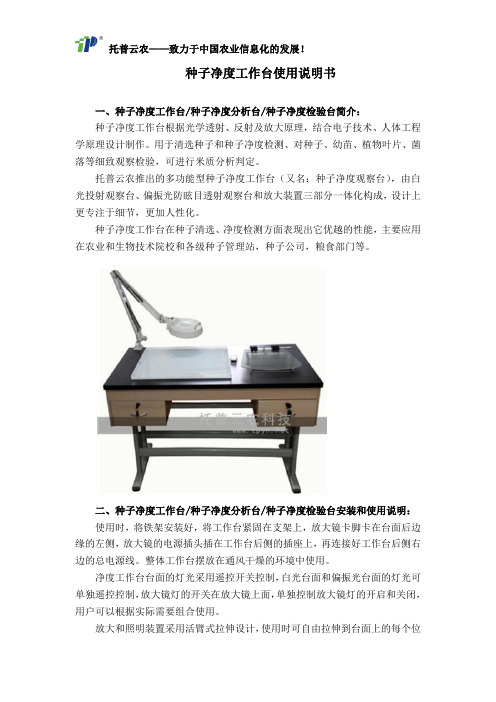
种子净度工作台使用说明书一、种子净度工作台/种子净度分析台/种子净度检验台简介:种子净度工作台根据光学透射、反射及放大原理,结合电子技术、人体工程学原理设计制作。
用于清选种子和种子净度检测、对种子、幼苗、植物叶片、菌落等细致观察检验,可进行米质分析判定。
托普云农推出的多功能型种子净度工作台(又名:种子净度观察台),由白光投射观察台、偏振光防眩目透射观察台和放大装置三部分一体化构成,设计上更专注于细节,更加人性化。
种子净度工作台在种子清选、净度检测方面表现出它优越的性能,主要应用在农业和生物技术院校和各级种子管理站,种子公司,粮食部门等。
二、种子净度工作台/种子净度分析台/种子净度检验台安装和使用说明:使用时,将铁架安装好,将工作台紧固在支架上,放大镜卡脚卡在台面后边缘的左侧,放大镜的电源插头插在工作台后侧的插座上,再连接好工作台后侧右边的总电源线。
整体工作台摆放在通风干燥的环境中使用。
净度工作台台面的灯光采用遥控开关控制,白光台面和偏振光台面的灯光可单独遥控控制,放大镜灯的开关在放大镜上面,单独控制放大镜灯的开启和关闭,用户可以根据实际需要组合使用。
放大和照明装置采用活臂式拉伸设计,使用时可自由拉伸到台面上的每个位置,方便放大和清晰观察。
净度工作台的白光投射观察台和偏振光防眩目透射观察平台都采用最新的高亮度低耗能的冷光源,避免了灯光发出的热量对种子、幼苗、菌落、试验活体样本等影响,从而真正保证了对样本的无损观察。
右侧的偏振光防眩目透射观察台由底座的光源、起偏装置和上盖的检偏装置三部分组成,使用时可以通过旋转上盖即可获得最佳的观察光源,能完全滤除背景光源的干扰,可进行对种子外形评判,切片观察,病理分析,品种鉴定以及种子发芽,幼苗生长叶片分析,菌落计数、米质分析等综合功能,并适于拍摄高质量的照片。
使用时,打开光源,所要观察的种子等样品放在台面上直接观察,组合偏振装置和放大镜即可实现最佳的观察和检测效果。
- 1、下载文档前请自行甄别文档内容的完整性,平台不提供额外的编辑、内容补充、找答案等附加服务。
- 2、"仅部分预览"的文档,不可在线预览部分如存在完整性等问题,可反馈申请退款(可完整预览的文档不适用该条件!)。
- 3、如文档侵犯您的权益,请联系客服反馈,我们会尽快为您处理(人工客服工作时间:9:00-18:30)。
长春工业大学机械制造装备设计课程设计说明书课程设计名称《机械制造装备设计》课程设计专业机械制造及其自动化班级 110101班学生姓名指导教师孙宝玉年月日目录摘要 (2)1.X-Y双坐标联动数控工作台 (2)1.1课程设计的目的 (2)1.2设计相关数据 (2)1.3设计要求 (2)2工作台设计参数设计 (3)2.1 总体结构 (3)2.2滚珠丝杠设计 (3)2.2.1计算动载荷 (3)2.2.2计算临界转速n k (3)2.3滚珠动导轨设计 (4)2.3.1计算行程长度寿命T s (4)2.3.2计算动载荷 (4)3.步进电机的选择 (5)3.1步距角的选择确定 (5)3.2步进电机转速校核 (6)3.2.1空载起动时电机轴总的负载转距T q (6)3.2.2工作正常时电机轴总负载转矩T g (7)3.2.3 电机最大静转矩T (8)s4. 结语 (9)5.参考文献 (9)摘要本设计从下达任务起,经过现场调查和查阅文献资料入手,历经三周的时间完成。
在设计中,首先根据课程设计所要求的技术参数确定机床设计中所需要的参数,然后确定工作台结构,查资料,主要的计算包括摩擦齿轮的校核、轴的校核、轴承的校核、键的校核、主轴的校核计算等。
原动机与主轴箱的动力传递采用的是带传动装置。
最后根据资料和参考同类机床来设计,并绘制其装配图。
1X——Y双坐标联动数控工作台1.1课程设计的目的本课程设计的目的在于培养学生对典型机电一体化产品机械结构的设计能力和对机电伺服系统的设计能力,在学习有关专业课程设计的基础上,进行机电系统设计的初等训练,掌握手册、标准、规范等资料的使用方法,培养分析问题的能力,为以后的毕业设计打下良好的基础。
1.2设计相关的数据工作台长×宽390×290工作台重量1800N工作台行程X=60~100mm Y=50~80mm脉冲当量变0.05~0.08mm/p1.3设计要求(1)工作台进给运动采用滚珠丝杠螺旋运动(2)滚珠丝杠支承方式;双推——简支型(3)驱动电机为反应式步进电机(4)步进电机与滚珠丝杠间采用齿轮降速,要求消除齿轮传动间隙2工作台结构参数设计2.1总体结构数控工作台采用步进电机驱动的开环控制结构,其单向驱动系统结构实际设计的工作台为X、Y双坐标联动工作台,工作台是由上拖板、中拖板、下拖板及导轨上移动,X、Y导轨方向互相垂直2.2滚珠丝杠设计2.2.1计算动载荷CjCj=L1/3×K F K H×F a(N)K F=1.4 K H=1.1K F K H分别由设计指导书表1.2查得,F由指导书表3丝杠材料造C r—WM N\n钢,滚道硬度为58~~62HRC使用寿命;T=15000h取丝杠转速;n=100r/min轴向工作载荷;F a=2800N则额定寿命;L=60Nt/106=90所以动载荷;C j=901/3×1.4×1.1×2800=19323.8N选取滚珠丝杠型号;4008—2.5(由设计指导书附录一)2.2.2计算临界转速n kn k=9910×f c2×d1/(μl)2由设计指导书表4查得;f c=3.93 μ=0.又知;4008—2.5型滚珠丝杠中径d2=40mm 滚珠直径d0=4.763∴螺纹滚道半径R=0.52d0=0.52×4.763=2.48偏心距;e=0.707(R-d0/2)=0.707(2.48-4.763/2)=0.07丝杠内径;d1=d2-2e+2R=40-2×0.07+2×2.48=35.18mm取丝杠工作长度;L x=150mm L y=100mm∴n k=9910×f c2d1/(μl)2可知;y向临界转速n k最大n kmax=9910×f c2d1/(μL y)2=(9910×3.932×35.18×10-3)/(2/3×2)2302884.55(r/min)>n max=10000r/min压杆稳定性计算;F k=π2EI a/(μl)2丝杠危险截面惯性矩;I a=πd14/64=π×0.035184/64=7.46×10-8可知X 向为危险截面 ∴应计算X 向压杆问题材料弹性模量;对于钢E=2.06×10¹¹(P a ) ∴临界载荷;F kmin =π2EI a /(μl)2=(π2×2.06×1011×7.46×10-8)/(0.07×0.35)2=2.75×106(N)∴ 安全系数S=F k /F a = F kmin /F a =983.2>[S]2.5~~3.3 ∴丝杠绝对安全 不会失稳∴丝杠选取无误,即选取4008—2.5型滚珠丝杠2.3滚珠动导轨设计导轨是工作台的重要组成部分,由于滚动导轨具有定位精度高、低速无爬行、移动轻便等显著优点,故本工作台系统设计选用滚动导轨。
本次导轨设计的主要任务是根据负载情况选用标准化滚动导轨,在选用过程中,主要进行额定载荷验算2.3.1计算行程长度寿命T sT s =2L S ×n ×60×T h /100(km)工作单行程长度知;L sx =0.15m L sy =0.10m往复次数;n x =np/2 L sx =100×8×10-3/(2×0.15)=2.67 n y =np/2 L sy =100×8×10-3/(2×0.1)=4.00 工作时间寿命;T h =15000(h) ∴行程长度寿命;T sx =2L sx ×n ×60×T h /1000=(2×0.35×2.67×60×15000)/1000 =1682.1(km)T sy =2L sy ×n ×60×T h /1000=(2×0.2×4.00×60×15000)/1000 =1440(km)2.3.2计算动载荷j cj c =13(/)w TcHs f k T f f fF mTf 、cf、Hf、wf 分别由指导书表5,6,7,8查得 Tf=1.0,cf=1.0,Hf=1.0,wf=1.8另取滑座个数 m=4寿命系数一般取k=501(km)作用在滑座上载荷F x =18000N F x =24000N ∴jx c=13(/)4*1*1*1xws f k F T=19689.9N ∴jyc=13(/)4*1*1*1yws f k F T=26275.1N由机电一体化设计基础表2-13查得 故选取滚动导轨型号为HJG —D353步进电机的选择3.1 步距角的选择确定∴α=*360i tδ传动系统传动比i 取4即i=4 工作台脉冲当量δ=0.05 滚动丝杠导程t=8(mm)α=﹙360°×0.05×4﹚/8=9°由设计指导书附录三选择步进电机型号为90BF001由机电一体化设计基础图5-33、5-34查得 减速器采用2级传动传动比分别为i 1=1.8 i 2=2.2 各传动齿轮齿数为;Z 1=20 Z 2 =36 Z 3=20 Z 4=44 模数m=2mm 齿宽b=20mm3.2 步进电机转速校核3.2.1空载起动时电机轴总的负载转距T qT q = T j + T μ + T o由机电一体化设计基础书中式(5-36)分别计算各传动件的转动惯量,其中齿轮的等交叉直径取分度圆直径1d=d 3=mz 1 =mz 3 =2×20=402d = mz 2 =2×36=72 4d = mz 4 =2×44=88 Sd=35.18mm丝杠长度取L=600mm∴J=432L d p π J z1 =J z3 =340.02100.047.832π-⨯⨯⨯⨯=3.92×10⁻⁵ (kg·m 2 ) J z2=340.02100.0727.832π⨯⨯⨯⨯ =4104.1-⨯(kg·m 2 )J z4=30.02100.0887.832π⨯⨯⨯⨯=4109.2-⨯(kg·m 2 )J s=340.6100.035187.832π⨯⨯⨯⨯ =4100.3-⨯(kg·m 2 )将各传动件转动惯量及工作台质量折算电动机轴得:总当量负载荷转动惯量 J d =J Z1+(J z1+J z2)/i 12+(J z4+Js)/i 2+(P/2πi)2m=3.9×10-5+(4.1×10-4+3.9×10-5)/1.82+(9.2×10-4+7.03×10-4)/42+(0.008/2π×4)2×80其中工作台小刀架质量为m,取m=80kg取电动机轴自身转动惯量Jm=0.8×10-3(kg ×m 2) 则步近电动机轴的总转动惯量:J=Jm+Jd=1.09×10⁻³设步近电机空载启动时间为50ms. 最大进给速度:V max =1.0m/min 导轨摩擦系数μ=0.2空载启动时,电动机轴的惯性转矩:T J=Tε=J×W max/∆f=(J×2πi×V max)/(P×∆t)=1.14(N×mm)电动机轴上的当量摩擦转矩:Tμ=(P×FΜ)/2πηi=(P×mgn)/2πηi=(0.008×80×9.8×0.2)/(2π×0.8×4)=0.06(N×m)其中伺服进给链的总效率η=0.8设滚珠丝杠螺母副的预紧力为最大轴向载荷的1/3,则因预紧力而引起,而折算到电动机轴上的附加摩擦转局为:T=P×F0×(1-η0)2=P×F wmax×(1-η02)2/(2πηi×3)=0.008×2800×(1-0.92)2/(2π×0.8×4×3)0.07(N×m)则电动机空载起动时电机轴总的负载转矩:T g=T j+Tμ+Tω=1.14+0.06+0.07=1.27(N×m)3.2.2工作正常时电机轴总负载转矩T g工作台的最大轴向负载折算到电动机轴上的负载转矩:Tω=(P×Fμmax)/2πηi=0.08×2800/(2π×0.8×4)=11.1(N×m)电动机正常工作时电机轴总负载转矩:T g=TΜ+T0+T W=0.06+0.07+11. 1=11.23(N×m)3.2.3 电机最大静转矩T s(1) 按空载启动计算:空载启动上所需电机最大静转矩T s1=T q/c=1.27/0.707=1.80(N×m)C=0.707 由设计指导书表查得:(2) 按正常工作计算:在最大外载荷下工作时所需要电动机最大静转矩: T s2=T g /(0.3~0.5)=1.24/(0.3~0.5)=3.89~2.48(N ×m)Ts ≥max{T s1,T s2} ∴ T s =3.89<[ T s ]∴ 步近电机的最大静转矩满足要求 (3) 频率校核!参考电机的转矩—频特性曲线原则:选用步近电机事应使实际应用的启动频率,运行频率与负载转矩所对应的启动,运行工作点位于该曲线之下,才能保证步近电机不失频地正常工作经校核满足要求∴ 选取90B0.01型步近电机4总语一转眼一个月的课程设计就要结束了。