六口千兆轻环网交换机使用说明书
交换机用户使用手册
交换机用户使用手册第二章、概述ISCOM1024E是一款具有VLAN和QoS功能的以太网交换机,它可提供24个10/100Mbps RJ45口,通过Console口管理。
支持Based-Port VLAN,支持802.1q VLAN;提供基于端口、基于Tag、基于TOS的QoS管理;支持丰富的端口功能管理;提供环路故障检测功能。
ISCOM1024E适合应用于小区及企业以太网的高速接入。
2.1包装物●一台ISCOM 1024E交换机●一根220V电源线●一本中文说明书●一根CBL-RS232-DB9F/RJ45-A-2m连接线缆第三章、技术参数3.1 基本特性:●24个自适应10/100Mbps及全双工/半双工工作模式的RJ45端口●每个端口都能自动检测MDI或MDI-X连接方式,交换机之间的连接不需要交叉线●支持CONSOLE管理●支持端口接收、发送独立各8档的带宽控制●支持流量控制●支持Based-Port VLAN和802.1q VLAN●支持基于端口的优先级服务,支持IEEE802.1P标准的服务等级,支持基于TOS/DeffServ优先级服务●提供环路故障检测功能●支持广播包的过滤3.2 技术指标:支持标准:IEEE802.3 10Base-T,IEEE 802.3u 100Base-TX IEEE802.3x介质支持:10Mbps:3,4,5类双绞线。
100Mbps:5类双绞线端口数量:24个RJ45 端口VLAN: 支持Based-Port VLAN和802.1q VLANQOS: 支持基于端口的优先级服务,支持IEEE802.1P标准的服务等级,支持基于TOS/DeffServ优先级服务端口安全性: 端口锁定(静态MAC地址驻留在过滤表中)环路故障检测:提供环路故障检测功能尺寸:440Wmm x 120Dmm x 43.6Hmm存储转发:全线速地址表:8K包缓存:160K 字节3.3 环境条件和电源要求:环境温度:0℃~50℃工作湿度:5% ~ 95%功耗:く15W电源:100-240V AC,50-60Hz第四章、结构及指示灯说明ISCOM1024E交换机前面板包括24个10/100M以太网接口,1个控制台接口,状态指示灯。
TG-NET%20S3100全千兆管理型交换机_用户手册pdf

S3100系列全千兆管理型交换机用户手册©copyright 2011 by Shenzhen TG-NET Botone Technology Co.,Ltd. All rights reserved.事先未征得深圳市万网博通科技有限公司(以下简称TG-NET)的书面同意,任何人不得以任何方式拷贝或复制本文档中的任何内容。
TG-NET不做与本文档相关的任何保证,不做商业性、质量或特定用途适用性的任何隐含保证。
本文档中的信息随时可能变更,而不另行通知。
TG-NET保留对本出版物做修订而不通知任何个人或团体此类变更的权利。
深圳市万网博通科技有限公司地址:深圳市龙华新区大浪街道华荣路北昱南通科技工业园2栋邮编:518109服务电话:400-088-7500网址:目录第一部分硬件安装指导 (5)第1章使用说明 (5)1.1用途 (5)1.2前面板 (5)1.3后面板 (7)第2章安装前的准备 (7)2.1注意事项 (7)2.2检查安装场所 (8)2.3安装工具 (8)第3章安装 (9)3.1交换机的安装 (9)3.2电源线及地线连接 (9)3.3安装完后的检查 (10)第4章技术资料详细说明 (11)第二部分WEB配置指导 (13)第1章系统登陆 (13)第2章设备状态 (14)2.1系统状态 (14)2.2端口统计 (15)2.3端口详细统计 (16)2.4LACP状态统计 (16)2.5RSTP信息统计 (17)2.6IGMP状态统计 (18)第3章设备基本配置 (19)3.1系统配置 (19)3.2端口配置 (20)3.3流量控制 (21)第4章设备高级配置 (22)4.1IGMP配置 (22)4.2VLAN配置 (22)4.3ARP配置 (27)4.4链路汇聚 (28)4.5LACP端口配置 (29)4.6RSTP系统配置 (30)4.7802.1X配置 (31)4.8端口镜像配置 (32)4.9QoS配置 (33)4.10风暴控制 (34)4.11PING (35)第5章系统维护 (36)5.1软件升级 (36)5.2配置管理 (37)5.3系统热重启 (38)5.4恢复出厂设置 (38)第三部分CLI配置指导 (40)第1章系统配置 (42)第2章C ONSOLE参数配置 (43)第3章端口配置 (44)第4章MAC配置 (45)第5章VLAN配置 (47)第6章ARP配置 (48)第7章端口聚合配置 (49)第8章LACP配置 (51)第9章快速生成树配置 (52)第10章用户组配置 (53)第11章Q OS配置 (54)第12章端口镜像配置 (56)第13章IP地址配置 (57)第14章D OT1X配置 (59)第15章IGMP配置 (60)第四部分附录常见故障诊断 (62)物品清单小心打开交换机包装盒,检查包装盒里面应有以下配件:一台S3100系列全千兆管理型交换机;一根交流电源连接线;一根DB9-RJ45串口线;一张用户手册光盘;一张保修卡与合格证;安装组件和其它配件;如果发现有所损坏或者任何配件短缺情况,请及时和当地经销商联系;第一部分硬件安装指导第1章使用说明1.1用途S3100系列交换机包括以下四个型号:1) S3100-24G:24个10/100/1000M电口,1个Console口;2) S3100-24G-2F:24个10/100/1000M电口,2个千兆SFP复用光口,1个Console口;3) S3100-16F-8G:16个千兆SFP光口,8个10/100/1000M电口,1个Console口;4) S3100-8F-8G:8个千兆SFP光口,8个10/100/1000M电口,1个Console口;本手册的用途是帮助您正确地使用S3100系列全千兆管理型交换机。
M型千兆以太网交换机用户手册_V4.1.0

第1章 1.1 1.2
第2章 2.1 2.2 2.3 2.4
第3章 3.1 3.2 3.3
第4章 4.1 4.2 4.3
使用说明 ..................................................................................................................................... 3 产品外观 ..................................................................................................................................... 3 术语解释 ..................................................................................................................................... 6 M 型交换机综述 ........................................................................................................................8 产品规格 ..................................................................................................................................... 8 功能特点 ..................................................................................................................................... 8 性能指标 ..................................................................................................................................... 9 整机组成 ................................................................................................................................... 12 安装前的准备 ........................................................................................................................... 14 注意事项 ................................................................................................................................... 14 检查安装场所 ........................................................................................................................... 14 安装工具 ................................................................................................................................... 15 安装 ........................................................................................................................................... 16 交换机的安装 ........................................................................................................................... 16 电源线及地线连接 ................................................................................................................... 16 安装完后的检查 ....................................................................................................................... 17
莫加工业级6口PoE以太网交换机产品说明书

P/N: 1802002060016 *1802002060016*EDS-P206A-4PoE Series Quick Installation GuideMoxa EtherDevice TM SwitchVersion 4.3, May 2021Technical Support Contact Information/support2021 Moxa Inc. All rights reserved.OverviewThe EDS-P206A-4PoE series industrial Ethernet switches are entry-level industrial 6-port PoE Ethernet switches that support IEEE 802.3, IEEE 802.3u, and IEEE 802.3x, with 10/100M, full/half-duplex, MDI/MDIX auto-sensing, IEEE 802.3af, and IEEE 802.3at.The EDS-P206A-4PoE series provides 12/24/48 VDC redundant power inputs that can be connected simultaneously to a live DC power source. The switches are available with a standard operating temperature range from -10 to 60°C, or with a wide operating temperature range from -40 to 75°C, and their IP30 metal housing makes them rugged enough for any harsh industrial environment.To provide greater versatility for use with applications from different industries, the EDS-P206A-4PoE switches also allow users to enable or disable broadcast storm protection with DIP switches on the outer panel.The EDS-P206A-4PoE switches can be easily installed on a DIN-Rail or in distribution boxes. The DIN-Rail mounting capability and IP30 metal housing with LED indicators make the plug-and-play EDS-P206A-4PoE switches reliable and easy to use.NOTE Throughout this Hardware Installation Guide, we use EDS as an abbreviation for Moxa EtherDevice Switch:EDS = Moxa EtherDevice SwitchPackage ChecklistYour EDS is shipped with the following items. If any of these items are missing or damaged, please contact your customer service representative for assistance.•Moxa EtherDevice™ Switch•Quick installation guide (printed)•Warranty cardFeaturesHigh-wattage Power-over-Ethernet•Up to 30 watts per PoE port•Active circuit protection•Auto disconnection for over-voltage or under-voltage•Power consumption detection and classificationHigh Performance Network Switching Technology•10/100BaseT(X) (RJ45 connector), 100BaseFX (SC/ST connector, multi/single-mode)•10/100M, Full/Half-Duplex, MDI/MDIX auto-sensing•IEEE 802.3/802.3u/802.3x•Store and Forward switching process type, 2K address entries Rugged Design•Redundant dual 12/24/48 VDC power input•Operating temperature range from -10 to 60°C, or extended operating temperature of -40 to 75°C for “T” models.•IP30 metal housing•DIN-Rail or panel mounting capabilityEDS-P206A-4PoE (Standard) Panel Layouts1.Grounding screw2.Terminal block for powerinput P1/P23.DIP switches4.Power input P1 LED5.Power input P2 LED6.PoE LED7.10/100BaseT(X) port8.TP port’s 10/100 MbpsLED9.Model name10.Screw hole for wallmounting kit11.DIN-Rail kitEDS-P206A-4PoE-M-SC/ST Panel LayoutsNOTE: The EDS-P206A-4PoE-S-SC/ST are identical in appearance to the EDS-P206A-4PoE-M-SC/ST.1.Grounding screw2.Terminal block for powerinput P1/P23.DIP switches4.Power input P1 LED5.Power input P2 LED6.PoE LED7.10/100BaseT(X) port8.TP port’s 10/100 MbpsLED9.Model name10.100BaseFX port11.FX port’s 100 Mbps LED12.Screw hole for wallmounting kit13.DIN-Rail kitEDS-P206A-4PoE-MM-SC/ST Panel Layouts NOTE: The EDS-P206A 4PoE-SS-SC/ST are identical in appearance to the EDS-P206A-4PoE- MM-SC/ST.1.Grounding screw Array2.Terminal block for powerinput P1/P23.DIP Switches4.Power input P1 LED5.Power input P2 LED6.PoE LED7.10/100BaseT(X) port8.TP port’s 10/100 MbpsLED9.Model name10.100BaseFX port11.FX port’s 100 Mbps LED12.Screw hole for wallmounting kit13.DIN-Rail kitMounting DimensionsUnit = mm (inch)DIN-Rail MountingThe aluminum DIN-Rail attachment plate should already be fixed to the back panel of the EDS when you take it out of the box. If you need to reattach the DIN-Rail attachment plate, make sure the stiff metal spring is situated towards the top, as shown in the figures below. STEP 1: Insert the top of the DIN-Rail into the slot just below the stiff metal spring.STEP 2: The DIN-Rail attachment unit will snap into place as shown below.To remove the EDS from the DIN-Rail, reverse Steps 1 and 2 above.Wall Mounting (optional)For some applications, you will find it convenient to mount the EDS-P206A-4PoE on the wall, as shown in the following figures. STEP 1: Remove the aluminum DIN-Railattachment plate from the EDS-P206A-4PoE’s rear panel, and then attach the wall mount plates as shown in the diagram at the right.STEP 2: Mounting the EDS-P206A-4PoE on the wall requires 4 screws. Use the switch, with wall mount plates attached, as a guide to mark the correct locations of the 4 screws. The heads of the screws should be less than 6.0 mm in diameter, and the shafts should be less than 3.5 mm in diameter, as shown in the figure at the right.NOTE Before tightening the screws into the wall, make sure the screw head and shank size are suitable by inserting the screw into one of the keyhole-shaped apertures of the wall mounting plates.Do not screw the screws in completely—leave about 2 mm to allowroom for sliding the wall mount panel between the wall and the screws. STEP 3: Once the screws are fixed in the wall, insert the four screw heads through the large parts of the keyhole-shaped apertures, and then slide the EDS-P206A-4PoE downwards, as indicated. Tighten the four screws for added stability.Wiring RequirementsYou should also pay attention to the following points: •Use separate paths to route wiring for power and devices. If power wiring and device wiring paths must cross, make sure the wires are perpendicular at the intersection point.NOTE: Do not run signal or communications wiring and power wiring in the same wire conduit. To avoid interference, wires with different signal characteristics should be routed separately. •You can use the type of signal transmitted through a wire todetermine which wires should be kept separate. The rule of thumb is that wiring that shares similar electrical characteristics can be bundled together.• Keep input wiring and output wiring separated.•We strongly advise labeling the wiring to all devices in the system.Grounding the EtherDevice SwitchGrounding and wire routing help limit the effects of noise due toelectromagnetic interference (EMI). Run the ground connection from the ground screw to the grounding surface prior to connecting devices.Wiring the Redundant Power InputsThe top two contacts and the bottom two contacts of the 4-contactterminal block connector on the EDS’s top panel are used for the EDS’s two DC inputs. Top and front views of one of the terminal block connectors are shown here.STEP 1: Insert the negative/positive DC wires into the V-/V+ terminals.STEP 2: To keep the DC wires from pulling loose, use a small flat-blade screwdriver to tighten the wire-clamp screws on the front of the terminal block connector.STEP 3: Insert the plastic terminal block connector prongs into the terminal block receptor, which is located on EDS’s top panel.Communication ConnectionsThe EDS-P206A-4PoE switches have 4, 5, or 6 10/100BaseT(X) Ethernet ports, and 2, 1, or 0 (zero) 100BaseFX multi/single-mode (SC/ST-type connector) fiber ports.10/100BaseT(X) Ethernet Port Connection10/100BaseT(X) ports located on the EDS’s front panel are used to connect to Ethernet-enabled devices. Below we show pinouts for both MDI (NIC-type) ports and MDI-X (HUB/Switch-type) ports, and also show cable wiring diagrams for straight-through and cross-over Ethernet cables. MDI Port Pinouts MDI-X Port Pinouts8-pin RJ45Pin Signal 1 Tx+ 2 Tx- 3 Rx+ 6Rx-Pin Signal 1 Rx+ 2 Rx- 3 Tx+ 6Tx-PoE 10/100BaseT(X) Ethernet Port ConnectionPoE 10/100BaseT(X) ports located on the EDS switch’s front panel are used to connect to PoE-enabled devices. The pinout follows the “Alternative A, MDI mode” of 802.3af/at standards. Please see the details in the following table. PoE Port Pinout8-pin RJ45Pin Data Power 1 Tx+V+ 2 Tx- V+ 3 Rx+ V- 6Rx-V-NOTE According to IEEE 802.3af/at standards, the PD shall be implemented to be insensitive to the polarity of the power supply and shall be able to operate per MDI mode and MDI-X mode. However, some PDs only support MDI mode or MDI-X mode only. The following figure shows how to select the correct cable between the PD and EDS-P206A-4POE.RJ45 (8-pin) to RJ45 (8-pin) Straight-Through Cable WiringRJ45 (8-pin) to RJ45 (8-pin) Cross-Over Cable WiringNOTE If the PD only supports MDI-X mode (V-, V-, V+, V+ for pins 1, 2, 3, 6), choose a cross-over Ethernet cable to connect the PD and the EDS switch. If the PD only supports MDI mode (V+, V+, V-, V- for pins 1, 2, 3, 6), choose a straight-through Ethernet cable between the PD and the EDS-P206A-4PoE switch.100BaseFX Ethernet Port ConnectionThe concept behind the SC/ST port and cable is straightforward. Suppose you are connecting devices I and II; contrary to electricalsignals, optical signals do not require a circuit in order to transmit data. Consequently, one of the optical lines is used to transmit data from device I to device II, and the other optical line is used transmit data from device II to device I, for full-duplex transmission.Remember to connect the Tx (transmit) port of device I to the Rx(receive) port of device II, and the Rx (receive) port of device I to the Tx (transmit) port of device II. If you make your own cable, we suggest labeling the two sides of the same line with the same letter (A-to-A and B-to-B, as shown below, or A1-to-A2 and B1-to-B2). SC-Port PinoutsSC-Port to SC-Port Cable WiringST-Port Pinouts ST-Port to ST-Port Cable WiringRedundant Power InputsBoth power inputs can be connected simultaneously to live DC power sources. If one power source fails, the other live source acts as a backup, and automatically supplies all of the EDS’s power needs. DIP Switch SettingsThe default setting for each DIP Switch isOFF. The following table explains the effectof setting the DIP Switches to the ONpositions.DIP SwitchSetting Description ––Serves no function (reserved for future use). BSPON Enables broadcast storm protection OFF Disables broadcast storm protectionLED IndicatorsThe front panel of the EDS switches contains several LED indicators. The function of each LED is described in the following table.LED Color State DescriptionP1 AMBER OnPower is being supplied to power inputP1.OffPower is not being supplied to powerinput P1.P2 AMBER OnPower is being supplied to power inputP2.OffPower is not being supplied to powerinput P2.10/100 AMBEROn TP port’s 10 Mbps link is active.Blinking Data is being transmitted at 10 Mbps.Off TP port’s 10 Mbps link is inactive. GREENOn TP port’s 100 Mbps link is active.Blinking Data is being transmitted at 100 Mbps.Off TP port’s 100 Mbps link is inactive.PoE+ AMBEROnThe PoE device is connected by theIEEE 802.3af standardBlinkingThe PoE power is shut off becausethere is insufficient powerOffNo PoE power output or no PoEconnected devicesGreenOnThe PoE device is connected by theIEEE 802.3at standardOffNo PoE power output or no PoEconnected devicesRedBlinkingPoE failure:-1 time/sec: PoE standard detectionfailure-2 times/sec: PoE current overload Off No PoE failureAuto MDI/MDI-X ConnectionThe Auto MDI/MDI-X function allows users to connect the EDS’s10/100BaseTX ports to any kind of Ethernet device, without needing to pay attention to the type of Ethernet cable being used for the connection. This means that you can use either a straight-through cable or cross-over cable to connect the EDS to Ethernet devices.Dual Speed Functionality and SwitchingThe Moxa EtherDevice Switch’s 10/100 Mbps switched RJ45 port auto negotiates with the connected device for the fastest data transmission rate supported by both devices. All models of Moxa EtherDevice Switch are plug-and-play devices, so that software configuration is not required at installation, or during maintenance. The half/full duplex mode for the switched RJ45 ports is user dependent and changes (by auto-negotiation) to full or half duplex, depending on which transmission speed is supported by the attached device. Broadcast Storm ProtectionThe EDS-P206A-4PoE Series has a built-in algorithm for limiting the amount of broadcast packets through the switch. This function is by default disabled and can be enabled by turning on the DIP switch labeled “BSP” on the top cover. If the broadcast storm protection algorithm detects more than 1k broadcast frames per second, then the switch will be suppressed from receiving broadcast frames for a period of 2 ms to prevent any further flooding.Switching, Filtering, and ForwardingEach time a packet arrives at one of the switched ports, a decision is made to either filter or forward the packet. Packets with source and destination addresses belonging to the same port segment will be filtered, constraining those packets to one port, and relieving the rest of the network from the need to process them. A packet with destination address on another port segment will be forwarded to the appropriate port, and will not be sent to ports where it is not needed. Packets that are used in maintaining the operation of the network (such as the occasional multi-cast packet) are forwarded to all ports. The EDS operates in the store-and-forward switching mode, which eliminates bad packets and enables peak performance to be achieved when there is heavy traffic on the network.Switching and Address LearningThe EDS has an address table that can hold up to 1024 addresses, which makes it suitable for use with large networks. The address tables are self-learning, so that as nodes are added or removed, or moved from one segment to another, the EDS automatically keeps up with new node locations. An address-aging algorithm causes the least-used addresses to be deleted in favor of newer, more frequently used addresses. To reset the address buffer, power down the unit and then power it back up.Auto-Negotiation and Speed SensingAll of the EDS’s RJ45 Ethernet ports independently support auto-negotiation for speeds in the 10BaseT and 100BaseTX modes, with operation according to the IEEE 802.3u standard. This means that some nodes could be operating at 10 Mbps, while at the same time, other nodes are operating at 100 Mbps. Auto-negotiation takes place when an RJ45 cable connection is made, and then each time a LINK is enabled. The EDS advertises its capability for using either 10 Mbps or 100 Mbps transmission speeds, with the device at the other end of the cable expected to advertise in a similar manner. Depending on what type of device is connected, this will result in agreement to operate at a speed of either 10 Mbps or 100 Mbps. If an EDS RJ45 Ethernet port is connected to a non-negotiating device, it will default to 10 Mbps speed and half-duplex mode, as required by the IEEE 802.3u standard. Total Power BudgetFor the total power budget, the EDS-P206A-4PoE will have 62 W at 12-17 VDC input, and 120 W at 18-57 VDC input. The total power budget is the total amount of reserved PoE power based on the PoE class of PoE device. If a newly connected PoE device causes the total reserved power to exceed the total power budget, the newly connected PoE device will be denied power.Input Voltage Total Power Budget12 VDC (12-17 VDC) 62 W24 VDC (18-35 VDC) 120 W48 VDC (36-57 VDC) 120 WPoE Class Reserved Power0 15.4 W1 4.0 W2 7.0 W3 15.4 W4 30 W SpecificationsTechnologyStandards IEEE 802.3 for 10BaseT,IEEE 802.3u for 100BaseT(X) and 100BaseFX,IEEE 802.3x for Flow ControlIEEE 802.3af for PoEIEEE 802.3at for PoE+Processing Type Store and ForwardFlow Control IEEE 802.3x flow control, back pressure flowcontrolInterfaceRJ45 Ports 10/100BaseT(X) auto negotiation speed, F/Hduplex mode, and auto MDI/MDI-X connection Fiber Ports 100BaseFX ports (SC/ST connector,multi/single-mode)LED Indicators P1, P2 (Power), 10/100M (TP port), and 100M(fiber port), PoEDIP Switch enable/disable broadcast storm protectionOptical Fiber100BaseFXMulti-mode Single-modeFiber Cable Type OM150/125 μmG.652 800 MHz*kmTypical Distance 4 km 5 km 40 kmWavelengthTypical (nm) 1300 1310TX Range (nm) 1260 to 1360 1280 to 1340 RX Range (nm) 1100 to 1600 1100 to 1600Optical PowerTX Range (dBm) -10 to -20 0 to -5 RX Range (dBm) -3 to -32 -3 to -34 Link Budget (dB) 12 29 Dispersion Penalty(dB)3 1Note: When connecting a single-mode fiber, we recommend using an attenuator to prevent damage caused by excessive optical power. Typical Distance To reach the typical distance of the specifiedfiber transceiver, please refer to the followingformula: Link budget(dB) > dispersionpenalty(dB) + total link loss(dB)PoETotal Power Budget 62 W @ 12 VDC (12-17 VDC)120 W @ 24/48 VDC (18-57 VDC)PoE Output Voltage 50 VDC @ 12/24/48 VDC power inputPoE Output Power 15.4 W for 802.3af, 30 W for 802.3atPoE Output Current 350 mA for 802.3af, 600 mA for 802.3at Overload CurrentProtection (at the port)SupportedPoE Pinout Mode A: Pair 1, 2 (V+); Pair 3, 6 (V-) PowerInput Voltage 12/24/48 VDC, redundant dual inputs Operating Voltage 12 to 57 VDCRated Current 6.19A @ 12VDC,5.55A @ 24 VDC,2.71A @ 48 VDCPower Consumption 13.2 W max., without PDs' consumption Inrush Current 64.56 A @ 48 VDC (0.1 - 1ms)Electrical Isolation 2250 VDC to chassis for 60 sHeat Dissipation 45.03 BTU/hOverload CurrentProtection (at theinput)SupportedReverse PolarityProtectionSupportedConnection 1 removable 4-contact terminal block Note: We strongly recommend using an isolated power supply with maximum output current of 7.5 A due to the power de-rating issue of the power supply at high operating temperatures.Moreover, without galvanic isolation between the redundant power inputs of this device, the V1+ and V2+ should use the same voltage.Physical CharacteristicsHousing Metal, IP30 protectionDimensions 50 x 114 x 70 mmWeight 275 gInstallation DIN-Rail Mounting, Wall Mounting (withoptional kit)Environmental LimitsOperating Temperature Standard models: -10 to 60°C (32 to 140°F) Wide temp. models: -40 to 75°C (-40 to 167°F)Storage Temperature -40 to 85°C (-40 to 185°F)Ambient RelativeHumidity5 to 95% (non-condensing)Regulatory ApprovalsSafety UL508EMI FCC Part 15, CISPR (EN55032) class AEMS IEC 61000-4-2 ESD: Contact 6 kV; Air 8 kVIEC 61000-4-3 RS: 20 V/m (80 MHz to 1 GHz)IEC 61000-4-4 EFT: Power 2 kV; Signal 1 kVIEC 61000-4-5 Surge: Power 2 kV; Signal 2 kVIEC 61000-4-6 CS: 10 VIEC 61000-4-8Shock IEC 60068-2-27Freefall IEC 60068-2-32Vibration IEC 60068-2-6WarrantyTime Period 5 yearsDetails /warrantyPatent/doc/operations/Moxa_Patent_Marking.pdf。
宇视 ISW5100-8GT4GP 管理型环网工业级千兆交换机 用户手册说明书
ISW5100-8GT4GP 管理型环网工业级千兆交换机 V1.0用户手册浙江宇视科技有限公司 第1页,共14页声明注意:本产品的默认密码仅供首次登录使用,为保证安全,强烈建议您将密码设置为强密码。
强密码:长度大于等于8位,且包含大写字母、小写字母、特殊字符、阿拉伯数字四者中3种或以上;中密码:长度大于等于8位,且包含大写字母、小写字母、特殊字符、阿拉伯数字四者中的2种;弱密码:长度小于8位,或者只包含大写字母、小写字母、特殊字符、阿拉伯数字四者中的1种。
∙本手册中的产品外观图仅供参考,请以实物为准。
∙截取的界面图仅当说明示例,各版本界面存在差异,请以实际界面为准。
∙本手册能作为多个型号产品的使用指导,但不一一列举每个产品的使用情况,请您根据实际产品自行对照。
∙本公司保留在没有任何通知或者提示的情况下对本手册的内容进行修改的权利,但并不确保手册内容完全没有错误。
∙由于物理环境等不确定因素,部分数据的实际值可能与手册中提供的参考值存在偏差,如有任何疑问或争议,请以本公司最终解释为准。
∙您使用产品过程中,请遵守本手册操作说明。
对于未按说明而引起的问题,我司恕不负责,感谢您的配合。
安全须知负责安装和日常维护本设备的人员必须具备安全操作基本技能。
在操作本设备前,请务必认真阅读和执行产品手册规定的安全规范。
∙此为A级产品,在生活环境中,该产品可能会造成无线电干扰。
在这种情况下,可能需要用户对其干扰采取切实可行的措施。
∙请确保设备安装平稳可靠,周围通风良好,设备在工作时必须确保通风口的畅通。
∙使设备工作在允许的温度及湿度范围内,避免置于潮湿,多尘,极热,极冷,强电磁辐射、震动等场所。
∙请确保环境电压稳定并符合设备供电要求,设备仅可在额定输入输出范围内使用,满足防雷要求,并良好接地。
∙请保护电源软线免受踩踏或挤压,特别是在插头、电源插座和从装置引出的接点处。
∙安装完成后请检查正确性,以免通电时由于连接错误造成人体伤害和设备部件损坏!∙请勿自行拆开设备机箱盖上的防拆封条。
飞鱼星VS-1016G全千兆以太网交换机用户手册

VOLANS VS-1016G
全千兆以太网交换机用户手册
VER: 20070403
、VOLANS、飞鱼星均为飞鱼星科技开发有限公司的商标。
对于本手册中出现的其他商标,由各自的所有人拥有。
由于产品版本升级或其它原因,本手册内容会不定期进行更新,为获得最新版本的信息,请定时访问公司网站。
飞鱼星科技试图在本资料中提供准确的信息,但对于可能出现的疏漏概不负责。
除非另有约定,本手册仅作为使用指导,本手册中的所有陈述、信息和建议不构成任何明示或暗示的担保。
全千兆交换机前面板u 指示灯
设备前面板提供各种端口及显示设备工作状态的指示灯
指示灯颜色描述
POWER 绿色常亮:加电正常
LINK/ACT 绿色常亮:连接状态
闪亮:数据传送状态1000M 绿色常亮:1000Mbps。
联想CE0128TB千兆以太网校园交换机产品指南说明书
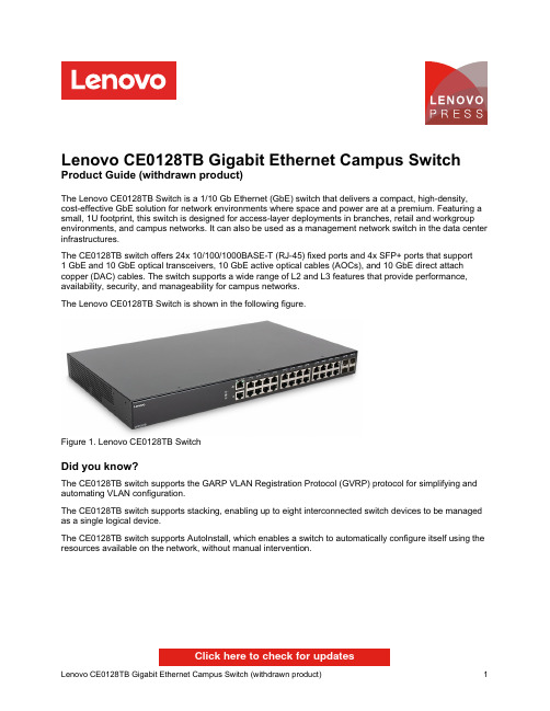
Lenovo CE0128TB Gigabit Ethernet Campus Switch Product Guide (withdrawn product)The Lenovo CE0128TB Switch is a 1/10 Gb Ethernet (GbE) switch that delivers a compact, high-density, cost-effective GbE solution for network environments where space and power are at a premium. Featuring a small, 1U footprint, this switch is designed for access-layer deployments in branches, retail and workgroup environments, and campus networks. It can also be used as a management network switch in the data center infrastructures.The CE0128TB switch offers 24x 10/100/1000BASE-T (RJ-45) fixed ports and 4x SFP+ ports that support1 GbE and 10 GbE optical transceivers, 10 GbE active optical cables (AOCs), and 10 GbE direct attach copper (DAC) cables. The switch supports a wide range of L2 and L3 features that provide performance, availability, security, and manageability for campus networks.The Lenovo CE0128TB Switch is shown in the following figure.Figure 1. Lenovo CE0128TB SwitchDid you know?The CE0128TB switch supports the GARP VLAN Registration Protocol (GVRP) protocol for simplifying and automating VLAN configuration.The CE0128TB switch supports stacking, enabling up to eight interconnected switch devices to be managed as a single logical device.The CE0128TB switch supports AutoInstall, which enables a switch to automatically configure itself using the resources available on the network, without manual intervention.Click here to check for updatesFigure 2. Front panel of the CE0128TB switchThe front panel of the CE0128TB switch includes the following components:24x RJ-45 ports for 10/100/1000 Mb Ethernet connections over twisted pair.4x SFP/SFP+ ports to attach SFP/SFP+ transceivers for 1 Gb or 10 Gb Ethernet connections, or DAC cables or AOCs for 10 Gb Ethernet connections.One RJ-45 10/100 Mb Ethernet port for out-of-band management.Figure 3. Rear panel of the CE0128TB switchThe rear panel of the CE0128TB switch contains the IEC 320-C14 power connector.The following table lists the supported cables and transceivers. Table 3. Supported SFP/SFP+ transceivers and cablesDescription Part number FeaturecodeMaximumquantityUTP Category 5e cables for RJ-45 fixed and management ports0.6m Blue Cat5e Cable40K56793801251.5m Blue Cat5e Cable40K8785380225 3m Blue Cat5e Cable40K5581380325 10m Blue Cat5e Cable40K8927380425 25m Blue Cat5e Cable40K8930380525 SFP transceivers - 1 GbELenovo 1000BASE-SX SFP Transceiver81Y162232694 Lenovo 1000BASE-LX SFP Transceiver90Y9424A1PN4 SFP+ transceivers - 10 GbELenovo Dual Rate 1/10Gb SX/SR SFP+ Transceiver00MY034ATTJ4 Lenovo 10Gb SFP+ SR Transceiver (10GBASE-SR)46C344750534 Lenovo 10GBASE-LR SFP+ Transceiver00FE331B0RJ4 Lenovo 10Gb SFP+ ER Transceiver (10GBASE-ER)90Y9415A1PP4 Lenovo 10GBASE-T SFP+ Transceiver7G17A03130AVV14 Optical cables for 1 GbE SX SFP and 10 GbE SR SFP+ transceiversLenovo 1m LC-LC OM3 MMF Cable00MN502ASR64 Lenovo 3m LC-LC OM3 MMF Cable00MN505ASR74 Lenovo 5m LC-LC OM3 MMF Cable00MN508ASR84 Lenovo 10m LC-LC OM3 MMF Cable00MN511ASR94 Lenovo 15m LC-LC OM3 MMF Cable00MN514ASRA4 Lenovo 25m LC-LC OM3 MMF Cable00MN517ASRB4 Lenovo 30m LC-LC OM3 MMF Cable00MN520ASRC4 SFP+ active optical cables - 10 GbELenovo 1m SFP+ to SFP+ Active Optical Cable00YL634ATYX4 Lenovo 3m SFP+ to SFP+ Active Optical Cable00YL637ATYY4 Lenovo 5m SFP+ to SFP+ Active Optical Cable00YL640ATYZ4 Lenovo 7m SFP+ to SFP+ Active Optical Cable00YL643ATZ04 Lenovo 15m SFP+ to SFP+ Active Optical Cable00YL646ATZ14 Lenovo 20m SFP+ to SFP+ Active Optical Cable00YL649ATZ24 SFP+ passive direct-attach cables - 10 GbELenovo 0.5m Passive SFP+ DAC Cable00D6288A3RG4 Lenovo 1m Passive SFP+ DAC Cable90Y9427A1PH4 Lenovo 1.5m Passive SFP+ DAC Cable00AY764A51N4 Lenovo 2m Passive SFP+ DAC Cable00AY765A51P4 Lenovo 3m Passive SFP+ DAC Cable90Y9430A1PJ4 Lenovo 5m Passive SFP+ DAC Cable90Y9433A1PK4 Lenovo 7m Passive SFP+ DAC Cable00D6151A3RH4SFP+ active direct-attach cables - 10 GbE Lenovo 1m Active DAC SFP+ Cable 00VX111AT2R 4Lenovo 3m Active DAC SFP+ Cable 00VX114AT2S 4Lenovo 5m Active DAC SFP+ Cable00VX117AT2T4DescriptionPart number Featurecode Maximum quantity The network cables that can be used with the switch are listed in the following table.Table 4. CE0128TB switch network cabling requirementsTransceiver StandardCableConnector10 Gb Ethernet10Gb SR SFP+(46C3447)1/10Gb SFP+ (00MY034)10GBASE-SRUp to 30 m with MMF cables supplied by Lenovo (see Table 3); up to 300 m with OM3 or up to 400 m with OM4MMF cables.LC 10Gb LR SFP+ (00FE331)10GBASE-LR Up to 10 km with 1310 nm SMF cables.LC 10Gb ER SFP+ (90Y9415)10GBASE-ER Up to 40 km with 1310 nm SMF cables.LC 10Gb RJ-45 SFP+(7G17A03130)10GBASE-T Up to 30 m with UTP Category 6a or 7 cables.RJ-45Active optical cables 10GBASE-SR Up to 20 m (see T able 3).SFP+DAC cables 10GSFP+CuUp to 7 m (see Table 3).SFP+1 Gb Ethernet Fixed 1 GbE ports 1000BASE-T Up to 25 m with UTP cables supplied by Lenovo (see Table 3); up to 100 m with UTP Category 5 or 5e cables.RJ-451Gb SX SFP (81Y1622)1/10Gb SFP+ (00MY034)1000BASE-SX Up to 30 m with MMF cables supplied by Lenovo (see Table 3); up to 550 m with 50 µ OM2 or 220 m with 62.5 µ OM1 MMF cables.LC1Gb LX SFP (90Y9424)1000BASE-LX Up to 10 km with 1310 nm SMF cables.LC Management ports 10/100 Mb Ethernet port 100BASE-TX Up to 25 m with UTP cables supplied by Lenovo (see Table 3); up to 100 m with UTP Category 5 or 5e cables.RJ-45Serial portRS-232DB-9-to-RJ-45 (comes with the switch).RJ-45Lenovo CE0152PB Switch (Limited Lifetime Warranty)7Z370022WW Lenovo RackSwitch G7028 (Rear to Front)7159BAX Lenovo RackSwitch G7052 (Rear to Front)7159CAX Lenovo RackSwitch G8052 (Rear to Front)7159G52 Lenovo ThinkSystem NE0152T RackSwitch (Rear to Front)7Y810011WW Lenovo ThinkSystem NE0152TO RackSwitch (Rear to Front, ONIE)7Z320O11WW 10 Gb Ethernet switchesLenovo ThinkSystem NE1032 RackSwitch (Rear to Front)7159A1X Lenovo ThinkSystem NE1032T RackSwitch (Rear to Front)7159B1X Lenovo ThinkSystem NE1072T RackSwitch (Rear to Front)7159C1X Lenovo RackSwitch G8124E (Rear to Front)7159BR6 Lenovo RackSwitch G8272 (Rear to Front)7159CRW Lenovo RackSwitch G8296 (Rear to Front)7159GR625 Gb Ethernet switchesLenovo ThinkSystem NE2572 RackSwitch (Rear to Front)7159E1X Lenovo ThinkSystem NE2572O RackSwitch (Rear to Front, ONIE)7Z210O21WW 100 Gb Ethernet switchesLenovo ThinkSystem NE10032 RackSwitch (Rear to Front)7159D1X Lenovo ThinkSystem NE10032O RackSwitch (Rear to Front, ONIE)7Z210O11WW Description Part number For more information, see the list of Product Guides in the Top-of-rack Switches category:/servers/options/switches#rt=product-guideStorage connectivityThe following table lists the external storage systems that are currently offered by Lenovo that can be used with the CE0128TB switch for external NAS or iSCSI SAN storage connectivity.Table 7. External storage systems: DE SeriesDescription Part number Worldwide JapanLenovo ThinkSystem DE Series Storage (iSCSI connectivity)Lenovo ThinkSystem DE2000H 10GBASE-T Hybrid Flash Array LFF7Y70A003WW7Y701001JP Lenovo ThinkSystem DE2000H 10GBASE-T Hybrid Flash Array SFF7Y71A002WW7Y711005JP Lenovo ThinkSystem DE2000H iSCSI Hybrid Flash Array LFF7Y70A004WW7Y701000JP Lenovo ThinkSystem DE2000H iSCSI Hybrid Flash Array SFF7Y71A003WW7Y711006JP Lenovo ThinkSystem DE4000H iSCSI Hybrid Flash Array 4U607Y77A000WW7Y771002JP Lenovo ThinkSystem DE4000H iSCSI Hybrid Flash Array LFF7Y74A002WW7Y74A002JP Lenovo ThinkSystem DE4000H iSCSI Hybrid Flash Array SFF7Y75A001WW7Y75A001JP Lenovo ThinkSystem DE4000F iSCSI All Flash Array SFF7Y76A002WW7Y76A002JP Lenovo ThinkSystem DE6000H iSCSI Hybrid Flash Array 4U607Y80A002WW7Y801000JP Lenovo ThinkSystem DE6000H iSCSI Hybrid Flash Array SFF7Y78A002WW7Y781000JP Lenovo ThinkSystem DE6000F iSCSI All Flash Array SFF7Y79A002WW7Y79A002JPTable 8. External storage systems: DM SeriesDescription Part number Lenovo ThinkSystem DM Series Storage (NAS or iSCSI connectivity)Lenovo ThinkSystem DM3000H Hybrid Storage Array (2U12 LFF, CTO only)7Y42CTO1WW Lenovo ThinkSystem DM3000H 48TB (12x 4TB HDDs) (Universal SFP+)7Y420001EA* Lenovo ThinkSystem DM3000H 48TB (12x 4TB HDDs) (10GBASE-T)7Y420002EA* Lenovo ThinkSystem DM5000H Hybrid Storage Array (2U24 SFF, CTO only)7Y57CTO1WW Lenovo ThinkSystem DM5000H 11.5TB (12x 960GB SSDs) (Universal SFP+)7Y570001EA* Lenovo ThinkSystem DM5000H 11.5TB (12x 960GB SSDs) (10GBASE-T)7Y570002EA* Lenovo ThinkSystem DM5000H 29TB (24x 1.2TB 10K HDDs) (Universal SFP+)7Y570003EA* Lenovo ThinkSystem DM5000H 29TB (24x 1.2TB 10K HDDs) (10GBASE-T)7Y570004EA* Lenovo ThinkSystem DM5000F Flash Storage Array (2U24 SFF, CTO only)7Y41CTO1WW Lenovo ThinkSystem DM7000H Hybrid Storage Array (3U, CTO only)7Y56CTO1WW Lenovo ThinkSystem DM7000F Flash Storage Array (3U, CTO only)7Y40CTO1WW * Available only in EMEA.Table 9. External storage systems: DS SeriesDescription Part numberWorldwide Japan PRC Lenovo ThinkSystem DS Series Storage (iSCSI connectivity)Lenovo ThinkSystem DS2200 LFF FC/iSCSI Dual Controller Unit4599A314599A3J4599A3C Lenovo ThinkSystem DS2200 SFF FC/iSCSI Dual Controller Unit4599A114599A1J4599A1C Lenovo ThinkSystem DS4200 LFF FC/iSCSI Dual Controller Unit4617A314617A3J4617A3C Lenovo ThinkSystem DS4200 SFF FC/iSCSI Dual Controller Unit4617A114617A1J4617A1C Lenovo ThinkSystem DS6200 SFF FC/iSCSI Dual Controller Unit4619A114619A1J4619A1C DS6200F 12x 400GB 10DWD SSDs, 1x 8Gb FC SFP, 512 Snapshots, Replication4619A1F4619J1F4619C1F DS6200F 12x 800GB 3DWD SSDs, 1x 8Gb FC SFP, 512 Snapshots, Replication4619A2F4619J2F4619C2F DS6200F 12x 1.6TB 3DWD SSDs, 1x 8Gb FC SFP, 512 Snapshots, Replication4619A3F4619J3F4619C3F DS6200F 12x 3.84TB 1DWD SSDs, 1x 8Gb FC SFP, 512 Snapshots, Replication4619A4F4619J4F4619C4FRack cabinetsThe following table lists the rack cabinets that are currently offered by Lenovo that can be used for mounting the CE0128TB switch and other IT infrastructure building blocks.Table 11. Rack cabinetsDescription Part number25U S2 Standard Rack (1000 mm deep; 2 sidewall compartments)93072RX 25U Static S2 Standard Rack (1000 mm deep; 2 sidewall compartments)93072PX 42U S2 Standard Rack (1000 mm deep; 6 sidewall compartments)93074RX 42U 1100mm Enterprise V2 Dynamic Rack (6 sidewall compartments)93634PX 42U 1100mm Enterprise V2 Dynamic Expansion Rack (6 sidewall compartments)93634EX 42U 1200mm Deep Dynamic Rack (6 sidewall compartments)93604PX 42U 1200mm Deep Static Rack (6 sidewall compartments)93614PX 42U Enterprise Rack (1105 mm deep; 4 sidewall compartments)93084PX 42U Enterprise Expansion Rack (1105 mm deep; 4 sidewall compartments)93084EXFor more information, see the list of Product Guides in the Rack cabinets category:/servers/options/racks#rt=product-guidePower distribution unitsThe following table lists the power distribution units (PDUs) that are currently offered by Lenovo that can be used for distributing electrical power to the CE0128TB switches and other IT infrastructure building blocks mounted in a rack cabinet.Table 12. Power distribution unitsDescription Part number0U Basic PDUs0U 36 C13/6 C19 24A/200-240V 1 Phase PDU with NEMA L6-30P line cord00YJ776 0U 36 C13/6 C19 32A/200-240V 1 Phase PDU with IEC60309 332P6 line cord00YJ777 0U 21 C13/12 C19 32A/200-240V/346-415V 3 Phase PDU with IEC60309 532P6 line cord00YJ778 0U 21 C13/12 C19 48A/200-240V 3 Phase PDU with IEC60309 460P9 line cord00YJ779 Switched and Monitored PDUs0U 20 C13/4 C19 Switched and Monitored 24A/200-240V/1Ph PDU w/ NEMA L6-30P line cord00YJ781 0U 20 C13/4 C19 Switched and Monitored 32A/200-240V/1Ph PDU w/ IEC60309 332P6 line cord00YJ780 0U 18 C13/6 C19 Switched / Monitored 32A/200-240V/346-415V/3Ph PDU w/ IEC60309 532P6 cord00YJ782 0U 12 C13/12 C19 Switched and Monitored 48A/200-240V/3Ph PDU w/ IEC60309 460P9 line cord00YJ783 1U 9 C19/3 C13 Switched and Monitored DPI PDU (without a line cord)46M4002 1U 9 C19/3 C13 Switched and Monitored 60A 3Ph PDU with IEC 309 3P+Gnd cord46M4003 1U 12 C13 Switched and Monitored DPI PDU (without a line cord)46M4004 1U 12 C13 Switched and Monitored 60A 3 Phase PDU with IEC 309 3P+Gnd line cord46M4005 Ultra Density Enterprise PDUs (9x IEC 320 C13 + 3x IEC 320 C19 outlets)Ultra Density Enterprise C19/C13 PDU Module (without a line cord)71762NXUltra Density Enterprise C19/C13 PDU 60A/208V/3ph with IEC 309 3P+Gnd line cord 71763NU C13 Enterprise PDUs (12x IEC 320 C13 outlets)DPI C13 Enterprise PDU+ (without a line cord)39M2816DPI Single Phase C13 Enterprise PDU (without a line cord)39Y8941C19 Enterprise PDUs (6x IEC 320 C19 outlets)DPI Single Phase C19 Enterprise PDU (without a line cord)39Y8948DPI 60A 3 Phase C19 Enterprise PDU with IEC 309 3P+G (208 V) fixed line cord 39Y8923Front-end PDUs (3x IEC 320 C19 outlets)DPI 30amp/125V Front-end PDU with NEMA L5-30P line cord 39Y8938DPI 30amp/250V Front-end PDU with NEMA L6-30P line cord 39Y8939DPI 32amp/250V Front-end PDU with IEC 309 2P+Gnd line cord 39Y8934DPI 60amp/250V Front-end PDU with IEC 309 2P+Gnd line cord 39Y8940DPI 63amp/250V Front-end PDU with IEC 309 2P+Gnd line cord 39Y8935Universal PDUs (7x IEC 320 C13 outlets)DPI Universal 7 C13 PDU (with 2 m IEC 320-C19 to C20 rack power cord)00YE443NEMA PDUs (6x NEMA 5-15R outlets)DPI 100-127V PDU with fixed NEMA L5-15P line cord 39Y8905Line cords for PDUs that ship without a line cord DPI 30a Line Cord (NEMA L6-30P)40K9614DPI 32a Line Cord (IEC 309 P+N+G)40K9612DPI 32a Line Cord (IEC 309 3P+N+G)40K9611DPI 60a Cord (IEC 309 2P+G)40K9615DPI 63a Cord (IEC 309 P+N+G)40K9613DPI Australian/NZ 3112 Line Cord (32A)40K9617DPI Korean 8305 Line Cord (30A)40K9618DescriptionPart number For more information, see the list of Product Guides in the Power Distribution Units category:/servers/options/pdu#rt=product-guideUninterruptible power supply unitsUninterruptible power supply unitsThe following table lists the uninterruptible power supply (UPS) units that are currently offered by Lenovo that can be used for providing electrical power protection to the CE0128TB switches and other IT infrastructure building blocks.Table 13. Uninterruptible power supply unitsDescription Part numberWorldwide modelsRT1.5kVA 2U Rack or Tower UPS (100-125VAC) (8x NEMA 5-15R 12A outlets)55941AX RT1.5kVA 2U Rack or Tower UPS (200-240VAC) (8x IEC 320 C13 10A outlets)55941KX RT2.2kVA 2U Rack or Tower UPS (100-125VAC) (8x NEMA 5-20R 16A outlets)55942AX RT2.2kVA 2U Rack or Tower UPS (200-240VAC) (8x IEC 320 C13 10A, 1x IEC 320 C19 16A outlets)55942KX RT3kVA 2U Rack or Tower UPS (100-125VAC) (6x NEMA 5-20R 16A, 1x NEMA L5-30R 24A outlets)55943AX RT3kVA 2U Rack or Tower UPS (200-240VAC) (8x IEC 320 C13 10A, 1x IEC 320 C19 16A outlets)55943KX RT5kVA 3U Rack or Tower UPS (200-240VAC) (8x IEC 320 C13 10A, 2x IEC 320 C19 16A outlets)55945KX RT6kVA 3U Rack or Tower UPS (200-240VAC) (8x IEC 320 C13 10A, 2x IEC 320 C19 16A outlets)55946KX RT8kVA 6U Rack or Tower UPS (200-240VAC) (4x IEC 320-C19 16A outlets)55948KX RT11kVA 6U Rack or Tower UPS (200-240VAC) (4x IEC 320-C19 16A outlets)55949KX RT8kVA 6U 3:1 Phase Rack or Tower UPS (380-415VAC) (4x IEC 320-C19 16A outlets)55948PX RT11kVA 6U 3:1 Phase Rack or Tower UPS (380-415VAC) (4x IEC 320-C19 16A outlets)55949PX ASEAN, HTK, INDIA, and PRC modelsThinkSystem RT3kVA 2U Standard UPS (200-230VAC) (2x C13 10A, 2x GB 10A, 1x C19 16A outlets)55943KT ThinkSystem RT3kVA 2U Long Backup UPS (200-230VAC) (2x C13 10A, 2x GB 10A, 1x C19 16A outlets)55943LT ThinkSystem RT6kVA 5U UPS (200-230VAC) (2x C13 10A outlets, 1x Terminal Block output)55946KT ThinkSystem RT10kVA 5U UPS (200-230VAC) (2x C13 10A outlets, 1x Terminal Block output)5594XKTFor more information, see the list of Product Guides in the Uninterruptible Power Supply Units category: /servers/options/ups#rt=product-guideLenovo Financial ServicesTrademarksLenovo and the Lenovo logo are trademarks or registered trademarks of Lenovo in the United States, other countries, or both. A current list of Lenovo trademarks is available on the Web athttps:///us/en/legal/copytrade/.The following terms are trademarks of Lenovo in the United States, other countries, or both:Lenovo®Lenovo ServicesRackSwitchThinkSystem®Other company, product, or service names may be trademarks or service marks of others.。
全网管控交换机用户手册说明书

全网管控交换机用户手册REV 2.00大连网月科技开发有限公司版权声明版权所有2006-2014,网月科技开发有限公司,保留所有权利。
使用本产品,表明您已经阅读并接受了EULA 中的相关条款。
如有变更,恕不另行通知。
遵守所生效的版权法是用户的责任。
在未经网月科技开发有限公司明确书面许可的情况下,不得对本文档的任何部分进行复制、将其保存或引进检索系统;不得以任何形式或任何方式(电子、机械、影印、录制或其他可能的方式)进行商品传播或用于任何商业、赢利目的。
网月科技开发有限公司拥有本文档所涉及主题的专利、专利申请、商标、商标申请、版权及其他知识产权。
在未经网月科技开发有限公司明确书面许可的情况下,使用本文档资料并不表示您有使用有关专利、商标、版权或其他知识产权的特许。
此处所涉及的其它公司、组织或个人的产品、商标、专利,除非特别声明,归各自所有人所有。
前言感谢您使用网月科技开发有限公司的全网管控交换机(以下文本中简称本产品)。
本产品是网月科技开发有限公司自主开发的二层智能以太网交换机,提供了多个千兆或万兆以太网端口,支持VLAN、端口镜像、防ARP欺骗、DHCP保护等功能,可以通过Web界面方式进行管理。
本产品针对目前局域网中出现的安全问题,提供了802.1x、Guest VLAN、防ARP欺骗、防蠕虫病毒、防MAC地址攻击、三元绑定等一系列安全特性,并且提供了可视化的WEB操作界面,通过简便操作,即可以有效防御ARP欺骗、DOS攻击及蠕虫攻击;交换机当中提供的多种VLAN功能,采用VLAN方式划分网络体系能够让管理员更加方便的管理企业网络,而VLAN网络灵活的扩展能力也让企业网络规模在不断扩大的同时不会出现网络混乱的情况,VLAN网络所具有的控制广播风暴能力让企业网络资源的性能得到大幅度提高,并且VLAN网络还具有管理简单,安全性高的特点。
同时本产品还支持DHCP保护功能,开启功能之后可以手动指定允许通过的DHCP服务的IP及MAC地址信息,非法的DHCP服务器会被交换机阻断掉,良好的解决酒店,出租屋等复杂环境的DHCP分配问题。
- 1、下载文档前请自行甄别文档内容的完整性,平台不提供额外的编辑、内容补充、找答案等附加服务。
- 2、"仅部分预览"的文档,不可在线预览部分如存在完整性等问题,可反馈申请退款(可完整预览的文档不适用该条件!)。
- 3、如文档侵犯您的权益,请联系客服反馈,我们会尽快为您处理(人工客服工作时间:9:00-18:30)。
6口千兆轻环网工业以太网交换机使用说明书
【概述】
六口千兆轻环网工业以太网交换机采用高强度IP40防护外壳,工业设计,提供全面的LED状态指示,支持宽电压12~48V DC电源输入,以增加通讯网络的可靠度,是二层工业以太网交换机。
6口工业交换机提供2~4个10/100/1000兆RJ45电口和2个1000兆SFP光口,可以根据业务口需求灵活的进行光电组合。
用于以太网冗余,环网自愈时间小于20ms;基于工业安装需求,提供导轨或壁挂式这两种安装模式。
工业交换机-40~85℃工作温度范围,能够满足各种工业现场的要求,提供便捷的以太网通讯解决方案。
【性能特点】
提供2~3个10/100/1000兆RJ45以太网接口,自动协商工作速率(10M/100M)和双工模式(半双工/全双工),接口、端口自
适应
提供2个1000兆SFP光口,可适配1000M SFP光模块
采用高强度IP40外壳及工业级EMC设计
支持宽电压12~48V DC电源输入
-40~85℃工作温度范围
【详细规格】
接口
RJ45电口:10/100/1000兆)速率自侦测、全/半双工模式,接口、端口自适应;
千兆光口:1000兆SFP,(选配1000兆或1000兆模块)
交换属性
十兆转发速度:14881pps
百兆转发速度:148810pps
千兆转发速度:1488096pps
传输方式:存储转发
系统交换带宽:12Gbps
缓存大小:2Mbits
MAC地址表:8K
电源
宽电压12~48V DC电源输入,典型工作电压12V/24V/48V,采用3芯7.62mm间距标准工业端子
空载功率:2光4电3.84W(@24VDC)
满载功率:2光4电7.2W(@24VDC)
机械特性
尺寸(W×H×D):40mm×128mm×100mm
净重:600克
外壳:IP40等级保护,金属外壳
安装:壁挂式或导轨式安装
工作环境
工作温度:-40℃~85℃
存储温度:-40℃~85℃
相对湿度:5%~95%(无凝露)
保修
保修期:5年
【包装清单】
初次使用交换机时,请首先检查包装随机的附件是否齐全。
6口千兆轻环网交换机包装清单如下:
6口千兆轻环网交换机一台(配工业接线端子,设备供电用)
说明书一份
保修卡一份
【注意事项】
请配置DC 12~48V工业标准电源,典型电压值为12V/24V/48V。
光口未使用时,必须用光纤帽盖好,以免污染光口。
请勿直视设备光纤输出口,以免激光损伤眼睛。
本设备属于精密通信设备,请切实做好设备的接地工作。
设备接地是通过侧板上专门的接地螺钉,安装时要使用专用的接地导
线进行接地。
【清单】
【导轨式安装】
采用标准导轨式安装,在大多数工业应用上非常方便,其安装步骤如下:
步骤1:检查是否具备导轨安装工具配件(已提供安装配件)。
步骤2:检查导轨是否固定结实,是否有安装的合适位置。
步骤3:将配件的导轨连接座下部卡入轨内(下部带弹簧支撑),然后将连接座的上部卡入导轨。
步骤4:将轨卡入轨连接座后,检查并确认产品可靠地安装到轨上。
CK6106M-4GTX2SFP CK6106M-2GTX2SFP
【LED指示灯】
【电源连接和拨码设置】
设备接地:交换机上侧板出有一接地螺丝,此点连接接地线的一端,另一端需可靠接入机房的大地。
接地线要求至少2.5 mm2,接地电阻要求在5欧姆以下。
电源输入(V+/V-):支持电源电压范围为DC12~48V,请使用0.75 mm2以上优质铜线。
拨码开关S1:设置环网使能,0表示不启用环网,1表示启用环网,只有启用了环网拨码开关S2~S4参数才有用。
拨码开关S2:设置环网主从设备,0表示从设备,1表示主设备,一个环网里面有且只有1个主设备,其他设备都为从设备。
拨码开关S3、S4:设置环网ID1~4,00表示环网ID为1,01表示环网ID为2,10表示环网ID为3,11表示环网ID为4,
环网口:设备7/FX1。