8-16-32 USB端口同步器系列搬砖多开说明书
Ultra High Speed 8-Port HDMI KVM Switcher说明书

SM-UHO-8P8-PORT HDMI KVM SWITCH WITH USB 2.0 SHARING and OSDACCESS AND CONTROL UP TO 8 HDMI COMPUTERS FROM A SINGLE USB KEYBOARD/MOUSE AND MONITOR through OSD FEATURES APPLICATIONS• Supports all major Operating Systems like Windows, Mac, Linux, Sun, Unix, DOS, etc.• 4K Ultra-HD resolution - supports up to 3840 x 2160 @ 30Hz• Supports DVI-D Single Link up to 1920 x 1080 @ 60 Hz • Simple OSD switching controls• Zero pixel loss with TMDS signal correction• Supports USB keyboard and mouse• Supports additional USB 2.0 devices like printers, scanners, web cameras and more• Flash upgradeable firmware• Stereo Audio support• Front panel keys for manual port selection• Hot-key commands for quick port selection• RS-232 for remote control• Independent (asynchronous) switching of KVM and peripheral USB/audio ports. Users can listen to audio from one computer while working on a different computer, orscan a document and save it on another computer• Complete keyboard emulation for error free booting • Server Collocation• Digital Signage• Education• Airports• Dealer Rooms• Control Rooms• Audio/Visual Presentations • Shopping Centers• Hotels/ResortsDesigned and Manufactured in the USAThe SM-UHO-8P is a dedicated multi-platform KVM Switch capable of managing up to 8 different computers through a single monitor, USB keyboard and mouse, a set of speakers and USB devices like printers, memory devices, scanners, etc.The SM-UHO-8P supports resolutions of up to 3840 x 2160 @ 30 Hz with zero pixel loss from TMDS signal correction.OVERVIEWThe main function of this KVM Switch is to centralize the access of several computer into a single,comprehensive KVM Station. Its USB 2.0 functionality support allows users at the console to access USBdevices that would otherwise be unavailable on conventional KVM Switches. For example, it allows the use of a flash memory drive or camera without having to plug it directly into the remote computer. The SM-UHO-8P is a perfect solution for the medical or industrial field where it may not be practical or safe to have on or more CPUs in the general vicinity.APPLICATION DIAGRAMFLEXIBLE CONTROLRS-232Any external device or program supporting RS-232 can control the SM-UHO-8P. The SM-UHO-8P uses a very simple protocol, enabling easy integration with the RS-232 control B/KEYBOARDHot keys enable the user to switch and control all the different functions of the KVM SwitchFLEXIBLE SHARINGSimple OperationINDEPENDENT SIMULTANEOUS DEVICE SELECTIONFlexibility is key with the SM-UHO-8P. It enables the use of a USB keyboard and mouse on one computer while other USB peripherals such as speakers, scanners and printers are connected to other computersources. The SM-UHO-8P maintains the ability to switch all connected devices to any one of the computer sources as with any other KVM Switch in the market.Switching between the display modes is simple: Use the buttons on the front panel, the programmable keyboard hotkeys, RS-232 commands or use the built-in on screen display (OSD). The OSD is accessible at the press of a button, and features controls for all of the SM-UHO-8P’s functions. The SM-UHO-8P is easily programmable through the setup function of the OSD.SM-UHO-8P BackSM-UHO-8P FrontScreenshots of the SM-UHO-8P’s OSDtechnical specificationsTel: (800) AVI-2131 (702) 800-00052455 W Cheyenne Ave, Suite 112North Las Vegas, NV 89032。
NetController 16-端口 1U 机柜挂载 KVM 切换器说明书

Important NoteCompatible with B040/42-Series KVM's only. Cannot be daisy-chained to other KVM series.16-Port 1U Rack-Mount USB/PS2 KVM Switch with On-Screen DisplayMODEL NUMBER:B042-016DescriptionThe NetController 16-port 1U rack-mount KVM Switch is an affordable, highly flexible enterprise-class KVM Switch, which allows the user to connect either USB or PS/2 keyboards and mice. In addition, P780-Series USB/PS2 combo KVM cable kits allow you to connect either USB or PS/2 computers, without the need to purchase separate cables or adapters. Control up to 16 directly connected computers, or expand the number of connected computers to up to 256 by daisy-chaining up to 15 additional B040/42-Series KVM switches (compatible with B040/42-Series KVMs only. Cannot be daisy-chained to other KVM series.). Switch between connected computers via the On-Screen Display (OSD), push buttons or keyboard hotkey commands. Other features include: password protection, auto-scanning, auto-logout, firmware upgrade and video support up to 2048 x 1536 (QXGA). Mounts easily in a standard 19-inch rack/cabinet and includes all necessary mounting hardware. Compatible with all major operating systems. Constructed of heavy-duty steel housing.FeaturesNetController 16-Port, 1U rackmount KVM switchqControl 16 computers via a single VGA monitor and USB or PS/2 keyboard/mouseqP780-Series USB/PS2 combo KVM cable kits allow you to connect either USB or PS/2 computers, without the need to purchase separate cables or adaptersqControl up to 256 computers by daisychaining up to 15 additional B040/42-Series KVM switches (Compatible with B040/42-Series KVM's only. Cannot be daisychained to other KVM series)qAllows for easy customization of ports by daisy-chaining any combination of B042-Series KVM's (4-, 8-or 16-port)qStandard 19" Rackmount size - hardware includedqOn-Screen Display (OSD) menu for intuitive operation and easy controlqSwitch between connected computers via the On-Screen Display (OSD), pushbuttons, or keyboard hotkey commandsqSupports video resolution up to 2048 x 1536q HighlightsNetController 16-Port, 1Urackmount KVM switchqControl 16 computers via asingle VGA monitor and USB orPS/2 keyboard/mouseqControl up to 256 computers bydaisychaining up to 15additional B040/42-Series KVMswitches (Compatible withB040/42-Series KVM's only.Cannot be daisychained to other KVM series)qP780-Series USB/PS2 comboKVM cables kits allow you toconnect either USB or PS/2computers, without the need topurchase separate cables oradaptersqCompatible with all majoroperating systemsqSystem Requirements Hardware VersionsA new hardware version (v2) of the B042-016 was released in 2019, requiring different firmware from the previous version (v1). The Support tab of this page includes a zip folder for v2. Along with the applicable firmware, it contains an FW Notes file to help you determine which hardware version you have and which firmware to use. The current firmware comes pre-installed on all v2 models. If you have a hardware version (v1) KVM, consult Technical Support for the applicable firmware.Note: *When daisy-chaining (8) or (16) Port KVM switches together and problems are experienced, confirm switches have the same hardware version. If firmware is not up to date, you may need to upgrade the firmware of yourunit(s).*Package IncludesB042-016 NetController 16-port1U rack-mount KVM switchqExternal Power Supply withNEMA 1-15P Plug (Input: 100-240V, 50/60 Hz, 0.3A / Output:9V 1A)qRack-mount hardwareq8 in. daisy-chain cable (forlonger daisy-chain cables, see qSpecificationsPassword protection and auto-logout features q Firmware upgradeableq Robust metal case design ensures best EMI/RFI shielding and video quality q Hot-swappable: disconnect and reconnect USB computers without rebooting q Supports standard 5-button Microsoft, Logitech, or comparable mice q Supports standard Microsoft, Logitech, or comparable keyboards q Compatible with all major operating systems q Constructed of heavy-duty steel housingqP781-Series cables)Daisy-chain terminator q 4 ft. HD15 to DB9 firmware upgrade cableqCD with owner's manual and quick start guide q Quick start guideq© 2023 Eaton. All Rights Reserved. Eaton is a registered trademark. All other trademarks are the property of their respective owners.。
USB 3 扩展器 4-端口点对点扩展器系统用户手册说明书
USB 3 Extenders4-Port Point-to-Point Extender SystemUser Guide Array Document 411-0024-30 Rev AJune 2018ContentsIntroduction (3)Features (3)Unpacking (3)A Quick Look at the USB 3 Extenders (4)The Local (Rx) Extender (4)The Remote (Tx) Extender (5)Installation (6)Preparing Your Site (6)Cabling Guidelines (6)Other Items You Will Need (6)Basic Connections (7)Optional Ethernet Pass-Through Connection (7)Connections for a Presenter BYOD Scenario (8)Installing the Extenders (8)Checking the Installation (8)Connecting a USB Device (9)Compatibility (9)Troubleshooting (9)Specifications (12)Technical Glossary (13)Contacting Technical Support (13)Compliance Statements and Declarations of Conformity (14)FCC Radio Frequency Interference Statement Warning (14)CE Statement (14)IC Statement (14)WEEE Statement (14)Product Operation and Storage (14)IntroductionThis guide provides product information, installation instructions and troubleshooting guidelines for Vaddio USB 3 Extenders. The instructions in this guide assume a general knowledge of computer installation procedures, familiarity with cabling requirements and some understanding of USB devices.FeaturesThis product enables you to extend USB 3.1 beyond the standard 3m cable limit for USB 3.1 peripheral devices. This product also supports USB 3.0, 2.0, and 1.1. This extender system is composed of two individual units, the Local Extender and the Remote Extender, and has the following key features:▪Support for new USB 3.1 host controllers and devices (up to 5 Gbps)▪Transparent USB extension supporting USB 3.1, 3.0, 2.0, and 1.1▪Up to 328 ft (100 m) of extension when directly connected over Cat-6/Cat-7 cable▪True plug and play; no software drivers required▪Works with all major operating systems: Windows®, macOS™, Linux® and Chrome OS™ Unpacking999-1005-032 – North America999-1005-132 – Europe and UKYour USB 3 Extender system contains:▪Local (Rx) extender▪Remote (Tx) extender▪USB 3.0 cable, 6 ft (1.8 m)▪Local extender 24V DC 1A power adapter with AC cord set(s)▪Remote extender 24V DC 2.71A power adapter with AC cord set(s)▪Quick-Start GuideA Quick Look at the USB 3 ExtendersThe local (receiver) and remote (transmitter) extenders look similar, but are not interchangeable. They use different power supplies as well. Please take the time to identify each part correctly.The Local (Rx) ExtenderThe local (receiver) extender connects to the computer using a standard USB 3.1 cable. Power for this unit is provided by the included 24V 1A adapter.Front ViewRear ViewITEM TYPE DESCRIPTION1 Power LED ON when DC is supplied to the extender unit. OFF when no power is supplied bythe AC Adapter.2 Mode Reserved for manufacturer use.3 Config Reserved for manufacturer use.4 Status LED ON when system is functioning normally. BLINKS when system is booting. BLINKS inunison with the LINK, USB 2, and USB 3 LEDs to indicate a temperature warning.5 Link LED ON when Local Extender is linked to an opposite Remote Extender. OFF whenthere is no connection between the Local and Remote Extenders.6 USB 2 LED ON when an active USB 2 connection is established through the extender system.BLINKS when the USB 2 connection is suspended/asleep. OFF when no USB 2connection is detected.7 USB 3 LED ON when an active USB 3 connection is established through the extender system.BLINKS when the USB 3 connection is suspended/asleep. OFF when no USB 3connection is detected.Ethernet pass through channel connects to a network or Ethernet device.8 LAN Port (100/1000Mbps)9 Link Port (RJ45) Accepts RJ45 connector for Cat-6/Cat-7 cabling to connect the Local Extender tothe Remote Extender.10 USB Host Port USB 3 Type B receptacle used to connect Local Extender to USB 3 Host computer.11 DC Power Port Locking connector for the included power adapter – accepts 24VDC 1A.The Remote (Tx) ExtenderThe remote (transmitter) extender provides USB 3.1 Type A ports for standard USB devices and allows you to connect up to four USB devices directly. The remote extender is powered by an external AC 24V 2.71A adapter, supplying up to 1.2 Amp per USB port. Additional devices may be connected by attaching up to three USB hubs to the remote extender.Front ViewRear ViewITEM TYPE DESCRIPTION1 Power LED ON when DC is supplied to the extender unit. OFF when no power is supplied by theAC Adapter.2 Mode Reserved for manufacturer use.3 Config Reserved for manufacturer use.4 Status LED ON when system is functioning normally. BLINKS when system is booting. BLINKS inunison with the LINK, USB 2, and USB 3 LEDs to indicate a temperature warning.5 Link LED ON when Remote Extender is linked to an opposite Local Extender. OFF when thereis no connection between the Local and Remote Extenders.6 USB 2 LED ON when an active USB 2 connection is established through the extender system.BLINKS when the USB 2 connection is suspended/asleep. OFF when no USB 2connection is detected.7 USB 3 LED ON when an active USB 3 connection is established through the extender system.BLINKS when the USB 3 connection is suspended/asleep. OFF when no USB 3connection is detected.8 LAN Port (100/1000Ethernet pass through channel connects to a network or Ethernet device.Mbps)9 Link Port (RJ45) Accepts RJ45 connector for Cat-6/Cat-7 cabling to connect the Remote Extender tothe Local Extender.10 Device Ports (Type A) Accepts all USB devices.11 DC Power Port Locking connector for the included power adapter – accepts 24VDC 2.71A.InstallationPreparing Your SiteBefore installing Vaddio USB 3 Extenders, you will need to prepare your site:1.Place the equipment where desired and set it up.2.Be sure your USB devices are within 328 ft (100 m) of the computer. If not, adjust the location of yourdevice(s) and/or computer accordingly.Cabling GuidelinesUse foiled (FTP) or shielded (STP) cabling if the cable run installation has any of these characteristics: ▪The cable is bundled with other cables▪The cable is run tight against other Category cables▪The cable is placed near sources of interference like power lines and radios▪The cable is looped or coiledThe maximum installation distance is 328 ft (100 m). This includes the length of any patch cables. Upto 33 ft (10 m) of patch cable can be used.For best performance, use shielded or foiled Cat-6/Cat-7 cable.When terminating cables, ensure the matching RJ45 connector is used for the cable type. Forexample, if Cat-6a cable is used, then Cat-6a compatible RJ45 connectors must be used.Otherwise, the benefits of using higher grade cabling may not be realized.When installing, ensure the cable is installed away from, or isolated from potential sources ofinterference such as electrical wiring, fluorescent lighting, etc.Other Items You Will NeedTo complete the installation, you will also require the following items that are not included with this system: ▪USB compatible computer (host computer) with a USB compliant operating system▪USB compatible device(s)▪Cat-6/Cat-7 unshielded twisted pair (UTP) cable and RJ45 connectors, ensuring the total cable length (including patch cables, if any) does not exceed 328 ft (100 m).Basic ConnectionsIn this scenario, USB and network connectivity extend to a camera installed some distance away.Optional Ethernet Pass-Through ConnectionThe USB 3 Extenders offer a 100/1000 Mbps Ethernet pass through connection that can be used for: ▪Connecting network devices▪Extending network access to the same location as the Remote Extender▪Leveraging existing cabling to provide USB connectivity without losing network connectivityOn one of the extenders, connect the LAN port to the network. On the other extender, connect the LAN port to the network port on a device requiring network connectivity.CAUTION: DO NOT CONNECT BOTH EXTENDERS TO THE NETWORK.Connections for a Presenter BYOD ScenarioIn this scenario, the presenter needs to run a soft conferencing application. The laptop’s USB is extended to the AV Bridge MatrixMIX elsewhere in the auditorium, with cameras (and possibly audio equipment) connected to it. The AV operator controls the video source for the conference. The presenter’s laptop is the local (Rx end) device, but the closest network connection is closer to the Remote (transmit) end equipment.Installing the ExtendersThe two extenders use different power supplies. Use the correct power supply for each extender.Using the wrong power supply on either extender could damage the system and void your warranty.1.Place the local (Rx) extender near the computer and use its 24V, 1A power supply to connect it to power.2.Connect the local extender’s Host port to a USB 3 port on the computer using the supplied USB3.1 cable.3.Place the remote (Tx) extender near the USB device.4.Connect the Link port on the local (Rx) extender to the Link port on the remote (Tx) extender using a Cat-6/Cat-7 cable.Do not exceed 33 ft (10 m) total of patch cable when using premise cabling.5.Connect the 24V, 2.71A power supply to the remote (Tx) extender and to power.Checking the Installation1.On both extenders, check that the Power, Status, Link, USB 2 and USB 3 LEDs are on. If the Link LEDs are off,check the cabling between the extenders. Correct the problem before continuing.2.Windows: On the connected computer, open Device Manager. Expand the entry for Universal Serial Buscontrollers by clicking the “+” sign. If the extenders are installed correctly, two instances of “GenericSuperSpeed USB Hub” are listed.Windows 7: Open the Start Menu, right click Computer, select Manage >> Device Manager.Windows 8, 8.1 or 10: Right click the Start Menu; select: Device Manager.3.MacOS: On the connected computer, o pen the System Profiler. In the left-hand column under Hardware,select “USB”. If the extender has been installed correctly, two separate instances of “Hub” are listed under the USB SuperSpeed Bus.To open System Profiler: Open the Finder, select Applications, then open the Utilities folderand double click on the System Profiler icon.4.If the extender system is not detected correctly or fails to detect, consult the T roubleshooting section.Connecting a USB Device1.If necessary, install any software required to operate the USB device. Refer to the documentation for theUSB device, as required.2.Connect the USB device to a USB device port on the Remote Extender.3.Check that the device is detected and installed properly in the operating system. CompatibilityThe USB 3 Extenders comply with USB 2.0 and USB 3.1 Gen 1 specifications governing the design of USB devices and suppo rt USB 3.1, 3.0, 2.0, and 1.1. Ho wever, there is no guarantee that all USB devices or hosts will be compatible as several factors affect the operation of USB devices over extended distances. TroubleshootingIf you are unable to resolve an issue after following these instructions, please contact Technical Support for further assistance.SpecificationsRANGEPoint-to-Point Up to 100m (328 ft) over CAT6a/7 CableUSB DEVICE SUPPORTMaximum Throughput 5 GbpsTraffic Types All Traffic TypesDevice Types All Device TypesMaximum Number of Devices and/or Hubs Up to 30 devicesLOCAL EXTENDERUSB Connector 1 x USB 3.1 Gen 1 Type B ReceptacleLink Connector 1 x RJ45 “LINK”Network Pass Through: 1 x RJ45 “LAN”Dimensions137.3mm x 232.1mm x 33.0mm (5.4” x 9.1” x 1.3”) Enclosure Material Black Anodized AluminumPower Supply100-240V AC Input, 24V 1A DC OutputREMOTE EXTENDERUSB Connector 4 x USB 3.1 Gen 1 Type A ReceptaclesLink Connector 1 x RJ45 “LINK”Network Pass Through: 1 x RJ45 “LAN”Dimensions137.3mm x 232.1mm x 33.0mm (5.4” x 9.1” x 1.3”) Enclosure Material Black Anodized AluminumAvailable Current Up to 1.2 Amp (6W) to each USB portPower Supply100-240V AC Input, 24V 2.71A DC OutputENVIRONMENTALOperating Temperature Range0°C – 50°C (32°F – 122°F)Storage Temperature Range-20°C – 70°C (-4°F – 158°F)Operating Humidity20% to 80% relative humidity, non-condensing Storage Humidity10% to 90% relative humidity, non-condensing COMPLIANCEEMC FCC (Class B), CE (Class B)Environmental RoHS2 (CE)Technical GlossaryCat-6a/Cat-7 Network Cabling –also called Category 6a/Category 7. T his cabling is available in either solid or stranded twisted pair copper wire variants and as UTP (unshielded t wisted pair), F TP (foiled t wisted pair) or STP (shielded twisted pair). UTP cables are not surrounded by any shielding making them more susceptible to electromagnetic interference (EMI). FTP/STP cables include shielding the copper wires and provide better protection against EMI.USB 3 and USB 2.0 Cables – have two distinct full-sized connectors. The Type A connector is used to connect the cable from a USB device to the Type A port on a computer or hub. The Type B connector is used to attach the USB cable to a USB device.RJ45 – the Registered Jack (RJ) physical interface connects the network cabling (Cat-6a/Cat-7) to the local (Rx) and remote (Tx) extenders. You may use either the T568A scheme (Table 1) or the T568B scheme (Table 2) for cable termination. The USB 3 Extenders require all four pairs of the cable. Note that any give cable must be terminated using the same T568 scheme on both ends to operate correctly.RJ45 Pin-OutsContacting Technical SupportIf you are experiencing problems not referenced in the Troubleshooting section, or require further assistance, contact Vaddio Technical Support.Compliance Statements and Declarations of ConformityFCC Radio Frequency Interference Statement WarningThis device complies with Part 15 of the FCC rules. Operation is subject to the following two conditions:(1) This device may not cause harmful interference, and (2) this device must accept any interference received including interference that may cause undesired operation.CE StatementThe original manufacturer declares that this product is in conformity with European Standards EN 55022, EN 55024, EN 55032 and EN 61000.IC StatementThis Class B digital apparatus complies with Canadian ICES-003 Issue 6.WEEE StatementThe European Union has established regulations for the collection and recycling of all waste electrical and electronic equipment (WEEE). Implementation of WEEE regulations may vary slightly by individual EU member states. Please check with your local and state government guidelines for safe disposal and recycling or contact your national WEEE recycling agency for more i nformation.Product Operation and StoragePlease read and follow all instructions provided with this product, and operate for intended use only.Do not attempt to open the product casing as this may cause damage and will void warranty. Use only the power supply provided with this product (if applicable). When not in use, product should be stored in a dry location between -20°C and 70°C.Vaddio is a brand of Milestone AV Technologies · Phone800.572.2011/+1.763.971.4400·Fax+1.763.971.4464·********************Visit us at for firmware updates, specifications, drawings, manuals, technical support information, and more. Vaddio is a trademark or registered trademark of Milestone AV Technologies. All other brand names or marks are used for identification purposes and are trademarks of their respective owners.In British Columbia, Milestone AV Technologies ULC carries on business as MAVT Milestone AV Technologies ULC.。
莫贾CN2600系列8和16端口RS-232 422 485终端服务器产品介绍说明书

CN2600Series8and16-port RS-232/422/485terminal servers with dual-LAN redundancyFeatures and Benefits•LCD panel for easy IP address configuration(excluding wide-temperaturerange models)•Dual-LAN cards with two independent MAC addresses and IP addresses•Redundant COM function available when both LANs are active•Dual-host redundancy can be used to add a backup PC to your system•Dual-AC-power inputs(for AC models only)•Real COM/TTY drivers for Windows and Linux•Universal high-voltage range:100to240VAC or88to300VDCCertificationsIntroductionRedundancy is an important issue for industrial networks,and various types of solutions have been developed to provide alternative network paths when equipment or software failures occur.“Watchdog”hardware is installed to utilize redundant hardware,and a“Token”-switching software mechanism is applied.The CN2600terminal server uses its built-in Dual-LAN ports to implement a“Redundant COM”mode that keeps your applications running uninterrupted.Dual-LAN RedundancyThe CN2600has two separate LAN ports that can be connected toseparate LAN networks.Dual-LAN redundancy involves setting uptwo separate physical networks to connect the PC host with theCN2600(the PC host also requires two LAN cards).If one connectionfails,the PC host can still communicate with your serial devices overthe alternative LAN connection.Redundant COMMoxa offers“Redundant COM,”an easy-to-use application to providean alternative solution for network redundancy.When the CN2600receives a data packet from a connected device,two identical datapackets are sent over two independent LAN connections to preventlost data packets if one LAN connection becomes unavailable.TheCN2600software is programmed to automatically discard duplicatedata packets.Dual-host RedundancyThe CN2600’s dual-LAN cards can also be used to set up“dual-host”redundancy.In this case,both networks(LAN A and LAN B in the figure)are connected to two different hosts.If either of the two hosts shuts down unexpectedly,the other host will still be able to communicate with serial devices connected to the CN2600.Dual-AC Model SupportedDual-power redundancy uses two power inputs and redundantinternal power supplies to ensure that all of the CN2600’s functionswill be available,even in the event of power circuit failures. AppearanceSpecificationsEthernet Interface10/100BaseT(X)Ports(RJ45connector)2Magnetic Isolation Protection 1.5kV(built-in)Ethernet Software FeaturesConfiguration Options CN2610-8/CN2610-16:Serial Console,Telnet Console,Windows Utility,Device SearchUtility(DSU)CN2650-8/CN2650-16/CN2600-2AC models:Serial Console,Telnet Console,WindowsUtility,Device Search Utility(DSU),Web console(HTTP/HTTPS)Management ARP,BOOTP,DDNS,DHCP Client,DNS,HTTP,IPv4,SMTP,SNMPv1/v2c/v3,TCP/IP,Telnet,UDP,ICMP,SLIPMIB MIB-IISecurity HTTPS/SSL,RADIUS,SSH,PAP,CHAPUnicast Routing RIPV1/V2,Static RouteWindows Real COM Drivers Windows95/98/ME/NT/2000,Windows XP/2003/Vista/2008/7/8/8.1/10(x86/x64),Windows2008R2/2012/2012R2(x64),Windows Embedded CE5.0/6.0,Windows XPEmbeddedLinux Real TTY Drivers Kernel versions:2.4.x,2.6.x,3.x,4.x,and5.xFixed TTY Drivers SCO UNIX,SCO OpenServer,UnixWare7,QNX4.25,QNX6,Solaris10,FreeBSD,AIX5.x,HP-UX11i,Mac OS XAndroid API Android3.1.x and laterSerial InterfaceConnector8-pin RJ45No.of Ports CN2610-8models:8CN2610-16models:16Serial Standards CN2610models:RS-232CN2650models:RS-232,RS-422,RS-485Operation Modes Real COM mode,TCP Server mode,TCP Client mode,UDP mode,RFC2217mode,Terminal mode,Reverse Telnet mode,PPP mode,DRDAS mode,Redundant COMmode,DisabledBaudrate50bps to921.6kbpsData Bits5,6,7,8Stop Bits1,1.5,2Parity None,Even,Odd,Space,MarkFlow Control None,RTS/CTS,DTR/DSR,XON/XOFFIsolation CN2650I Series:2kVRS-485Data Direction Control ADDC®(automatic data direction control)Pull High/Low Resistor for RS-4851kilo-ohm,150kilo-ohmsTerminator for RS-485120ohmsConsole Port RS-232(TxD,RxD,GND),8-pin RJ45(19200,n,8,1)Serial SignalsRS-232TxD,RxD,RTS,CTS,DTR,DSR,DCD,GNDRS-422Tx+,Tx-,Rx+,Rx-,GNDRS-485-4w Tx+,Tx-,Rx+,Rx-,GNDRS-485-2w Data+,Data-,GNDPower ParametersNo.of Power Inputs CN2600Series:1CN2600Series-2AC models:2Input Current CN2600Series:130mA@110VACCN2600Series-HV models:200mA@88VDCInput Voltage AC models:100to240VAC,47to63HzDC models:110VDC(88to300VDC)ReliabilityAutomatic Reboot Trigger Built-in WDTAlert Tools Built-in buzzer and RTC(real-time clock)Physical CharacteristicsHousing MetalInstallation19-inch rack mountingDimensions(with ears)480x198x45.5mm(18.9x7.80x1.77in)Dimensions(without ears)440x198x45.5mm(17.32x7.80x1.77in)Weight CN2610-8/CN2650-8:2,410g(5.31lb)CN2610-16/CN2650-16:2,460g(5.42lb)CN2610-8-2AC/CN2650-8-2AC/CN2650-8-2AC-T:2,560g(5.64lb)CN2610-16-2AC/CN2650-16-2AC/CN2650-16-2AC-T:2,640g(5.82lb)CN2650I-8:3,666g(8.08lb)CN2650I-16:3,776g(8.32lb)CN2650I-8-2AC:3,932g(8.67lb)CN2650I-16-2AC:4,022g(8.87lb)CN2650I-8-HV-T:3,910g(8.62lb)CN2650I-16-HV-T:3,930g(8.66lb)Environmental LimitsOperating Temperature Standard Models:0to55°C(32to131°F)Wide Temp.Models:-40to75°C(-40to167°F)CN2650-HV-T Models:-40to85°C(-40to185°F)Storage Temperature(package included)Standard Models:0to55°C(32to131°F)CN2650-8-2AC-T/CN2650-16-2AC-T:-40to75°C(40to167°F)CN2650I-8-HV-T/CN2650I-16-HV-T:-40to85°C(-40to185°F) Ambient Relative Humidity5to95%(non-condensing)Standards and CertificationsEMC EN55032/24EMI CISPR32,FCC Part15B Class AEMS AC models:IEC61000-4-2ESD:Contact:8kV;Air:15kVIEC61000-4-3RS:80MHz to1GHz:10V/mIEC61000-4-4EFT:Power:4kV;Signal:2kVIEC61000-4-5Surge:Power:2.5kV;Signal:1kVIEC61000-4-6CS:150kHz to80MHz:3V/m;Signal:3V/mIEC61000-4-8IEC61000-4-11DIPsHVDC models:IEC61000-4-2ESD:Contact:4kV;Air:8kVIEC61000-4-3RS:80MHz to1GHz:3V/mIEC61000-4-4EFT:Power:4kV;Signal:2kVIEC61000-4-5Surge:Power:2kV;Signal:1kVIEC61000-4-6CS:150kHz to80MHz:3V/mIEC61000-4-8Safety UL60950-1Vibration IEC60068-2-6Freefall IEC60068-2-32DeclarationGreen Product RoHS,CRoHS,WEEEMTBFTime CN2610-8:831,925hrsCN2610-16:639,332hrsCN2610-8-2AC/CN2650-8-2AC:773,268hrsCN2610-16-2AC:604,346hrsCN2650-8:657,123hrsCN2650-16:457,175hrsCN2650-16-2AC:442,699hrsCN2650I-8/CN2650I-8-2AC/CN2650-8-2AC-T:190,562hrsCN2650I-16/CN2650I-16-2AC/CN2650-16-2AC-T:115,887hrsCN2650I-8-HV-T:191,326hrsCN2650I-16-HV-T:116,924hrsStandards Telcordia(Bellcore)Standard TR/SRWarrantyWarranty Period5yearsDetails See /warrantyPackage ContentsDevice1x CN2600Series terminal serverInstallation Kit1x rack-mounting kitCable1x RJ45-to-DB9console cable1x power cord,suitable for your region(AC models) Documentation1x quick installation guide1x warranty cardDimensionsOrdering InformationModel Name Serial Standards No.of Serial Ports Serial Connector Isolation No.of PowerInputsPower Input Operating Temp.CN2610-8RS-23288-pin RJ45–1100-240VAC0to55°C CN2610-16RS-232168-pin RJ45–1100-240VAC0to55°C CN2610-8-2AC RS-23288-pin RJ45–2100-240VAC0to55°C CN2610-16-2AC RS-232168-pin RJ45–2100-240VAC0to55°C CN2650-8RS-232/422/48588-pin RJ45–1100-240VAC0to55°C CN2650-16RS-232/422/485168-pin RJ45–1100-240VAC0to55°C CN2650-8-2AC RS-232/422/48588-pin RJ45–2100-240VAC0to55°C CN2650-8-2AC-T RS-232/422/48588-pin RJ45–2100-240VAC-40to75°C CN2650-16-2AC RS-232/422/485168-pin RJ45–2100-240VAC0to55°C CN2650-16-2AC-T RS-232/422/485168-pin RJ45–2100-240VAC-40to75°C CN2650I-8RS-232/422/4858DB9male2kV1100-240VAC0to55°C CN2650I-16RS-232/422/48516DB9male2kV1100-240VAC0to55°CCN2650I-8-2AC RS-232/422/4858DB9male2kV2100-240VAC0to55°CCN2650I-16-2AC RS-232/422/48516DB9male2kV2100-240VAC0to55°CCN2650I-8-HV-T RS-232/422/4858DB9male2kV188-300VDC-40to85°C CN2650I-16-HV-T RS-232/422/48516DB9male2kV188-300VDC-40to85°C Accessories(sold separately)CablesCBL-F9M9-20DB9female to DB9male serial cable,20cmCBL-F9M9-150DB9female to DB9male serial cable,1.5mCBL-RJ45M25-1508-pin RJ45to DB25male serial cable,1.5mCBL-RJ45SF25-1508-pin RJ45to DB25female serial cable with shielding,1.5mCBL-RJ45F25-1508-pin RJ45to DB25female serial cable,1.5mCBL-RJ45M9-1508-pin RJ45to DB9male serial cable,1.5mCBL-RJ45SM9-1508-pin RJ45to DB9male serial cable with shielding,1.5mCBL-RJ45SF9-1508-pin RJ45to DB25male serial cable with shielding,1.5mCBL-RJ45SM25-1508-pin RJ45to DB9female serial cable with shielding,1.5mCBL-RJ45F9-1508-pin RJ45to DB9female serial cable,1.5mConnectorsMini DB9F-to-TB DB9female to terminal block connectorPower CordsPWC-C13AU-3B-183Power cord with Australian(AU)plug,1.83mPWC-C13CN-3B-183Power cord with three-prong China(CN)plug,1.83mPWC-C13EU-3B-183Power cord with Continental Europe(EU)plug,1.83mPWC-C13JP-3B-183Power cord with Japan(JP)plug,7A/125V,1.83mPWC-C13UK-3B-183Power cord with United Kingdom(UK)plug,1.83mPWC-C13US-3B-183Power cord with United States(US)plug,1.83mRack-Mounting KitsWK-45-01Rack-mounting kit,2L-shaped plates,8screws,45x57x2.5mm©Moxa Inc.All rights reserved.Updated Feb17,2020.This document and any portion thereof may not be reproduced or used in any manner whatsoever without the express written permission of Moxa Inc.Product specifications subject to change without notice.Visit our website for the most up-to-date product information.。
8口USB自动KVM切换器使用说明书(带OSD菜单功能)
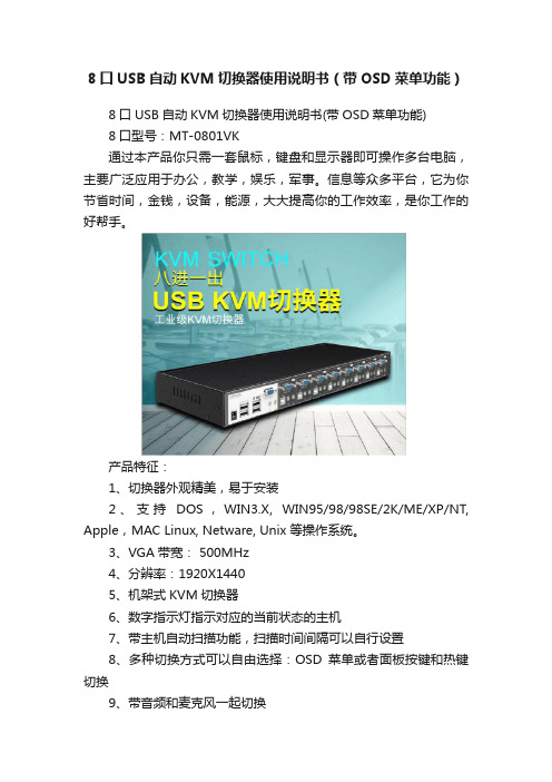
8口USB自动KVM切换器使用说明书(带OSD菜单功能)8口USB自动KVM切换器使用说明书(带OSD菜单功能)8口型号:MT-0801VK通过本产品你只需一套鼠标,键盘和显示器即可操作多台电脑,主要广泛应用于办公,教学,娱乐,军事。
信息等众多平台,它为你节省时间,金钱,设备,能源,大大提高你的工作效率,是你工作的好帮手。
产品特征:1、切换器外观精美,易于安装2、支持DOS,WIN3.X, WIN95/98/98SE/2K/ME/XP/NT, Apple,MAC Linux, Netware, Unix 等操作系统。
3、VGA带宽: 500MHz4、分辨率:1920X14405、机架式KVM切换器6、数字指示灯指示对应的当前状态的主机7、带主机自动扫描功能,扫描时间间隔可以自行设置8、多种切换方式可以自由选择:OSD菜单或者面板按键和热键切换9、带音频和麦克风一起切换切换方法:A、前面板上的按键主机1-8:直接按按键①-----⑧B、键盘上的热键调出OSD菜单:“SCROLL”,“SCROLL”然后根据菜单上的说明自主选择切换或者扫描。
OSD菜单说明:A、“ON”指示主机的连接状态。
带三角符号表示该主机已经连接KVM并且已经开机,不带三角符号表示当前端口的主机没有连接或者没有开机B、“ESC”表示按下键盘上的“ESC”按键,退出当前菜单C、“Enter”表示按下键盘上“Enter”按键,切换到红条指示的主机,并退出当前OSD菜单D、“F2”表示,在当前菜单条件下,按下键盘上的“F2”按键,退出当前OSD菜单,并执行扫描功能。
扫描从当前主机开始,回到当前主机结束。
数字指示灯指示当前主机状态:LED上的三位数字中,最右边表示输出,此处恒为“1”,左边两位指示当前主机,例如:“03”表示当前是操作第三台主机,“14”表示当前是操作第十四台主机使用步骤:1)用配线将主机逐个和KVM切换器连接好配线中带音频头,麦克风头,USB头,VGA头的一端连接主机配线中单个的VGA头连接到KVM的主机端口2)将鼠标,键盘,显示器,音箱,麦克风和KVM切换器的控制端连接好3)按顺序给各台主机上电,在一台主机完全启动后(鼠标键盘可以正常操作了之后),再接着启动另一台主机,直到所有的主机完全启动启动扫描方式:键盘OSD菜单热键:“SCROLL”,“SCROLL”,“F2”扫描顺序是从当前状态的主机开始,回到当前状态的主机结束,例如:当前是第5台主机,开始扫描时,到第6台主机,结束后回到第5台主机。
迈拓8口同步器说明书

迈拓8口同步器说明书迈拓8口同步器,它是一种具有多口同步器功能的高科技产品。
它可以用于连接和控制多台电脑同步运行。
它可以通过无线方式控制计算机终端用户输入的任何指令,例如鼠标的键程关系、键盘的键位数量等。
用户只需简单地控制多台电脑中每个键位的工作时间即可获得同步显示效果。
当然,如果用户想要增加电脑端输入量就需要通过手机APP进行控制。
通过软件设定每个键位的时间大小,通过对网络中多台电脑进行同步显示,可以让用户实时了解电脑各个工作状态下的运行状态。
1.同步器主体迈拓8口同步器主体由8个无线同步功能按钮、6个无线接收按键、6个2.4 G无线发射按键和1个同步器工作指示灯组成。
在所有8口同步器的主体结构中,最下面的一个按键为信号发射开关。
在每一个信号发射开关上都有一个红色的数字指示灯,代表着当前输出功率的大小。
当信号源与同步器供电电路连接时,红色指示灯就会闪烁并点亮。
为了便于使用,每个按钮均有各自不同的颜色显示。
2.连接步骤在同步器产品的说明书上,我们可以看到有安装程序和安装说明。
如果用户想要使用该产品,我们需要在购买同步器产品后下载安装程序,并在安装时将安装在用户当前电脑的主板上,然后使用主板上软件中“软件启动”按钮将安装程序切换到安装界面,接着使用主机中软件“管理”按钮将主机与同步器或网络进行设置。
完成后,如果用户想将电脑中全部键都同步至笔记本电脑中,我们需要在电脑中安装“多口同步器”软件并根据自己需要在软件中设置键盘及其他参数,之后再在同步器管理软件中进行管理。
在设置页面中有8个按键功能:数字键盘键、数字键。
用户只需在每一键设置该按键功能,最后再在同步器管理软件中通过选择键盘、数字键盘键、数字键等按键进行相应设置。
用户只需在这8个键位中进行多达7个键位的配置操作即可获得控制面板中所有按键功能同时工作自动同步到笔记本电脑中;如果你有自己喜欢的键盘及数字键盘键,需要把这种带有8口同步器功能连接至主机后再对其进行配置操作,否则无法实现同步操控功能。
MXU-88 Plus 8X8 4K HDMI USB 2.0 矩阵开关说明书
MXU -88 PlusUser ManualRemote access and control of up to 8 computers with 4K HDMI and transparent USB 2.0 from up to 8 connected stations8X8 4K HDMI / USB 2.0 Matrix Switch with Remote ControlBrackets for mounting can be ordered from SmartAVI.Front ViewRear ViewMXU-88Rear ViewSmart MUX HUBMXU-Control UnitFront View Rear ViewMXU-88 Plus InstalledINTRODUCTIONThe MXU-88 Plus is the latest upgrade to one of SmartAVI’s most powerful and efficient matrix switching solutions. This 8X8 switching hub grants up to eight users shared remote access to as many as eight re-mote work stations and transparent USB 2.0 devices. Great for applications such as multi-user remote supervision or group-based video editing projects, the MXU-88 Plus excels even more at expediting work-flow for digital devices of various kinds.Capable of displaying HDMI-based video at resolutions up to 4K (3840×2160 @ 30Hz), the MXU-88 Plus is perfect for non-emulation KVM operations where a high degree of picture clarity is imperative. Better yet, the MXU-88 Plus is easy to control, outfitted with a simple two-button front panel interface and a web-based command console via Ethernet connection. The MXU-88 Plus’s 16-port USB 2.0 output is ideal for transparent peripherals like keyboads, mice, external hard-drives, cameras, printers, scanners, streaming devices, and more. For comprehensive matrix switching and USB 2.0 device control remotely made easy, choose the MXU-88 Plus matrix switch powered by SmartAVI!The MXU-88 is an ideal solution for medical, industrial, studio and defense applications, where it is not practical or safe to have multiple workstations in close proximity to each other. An operator can switch to any connected computer from any connected station with ease.FEATURES∙ Remote control via SmartMUX HUB and MUX Control Units∙ (8) HDMI inputs with resolutions up to 4K (3840x2160 @ 30Hz)∙ (8) HDMI outputs with resolutions up to 4K (3840x2160 @ 30Hz)∙ (8) USB 2.0 Type B inputs—(8) Dual USB 2.0 Type A outputs∙ Supports digital audio over HDMI∙ Supports DVI-D with adapters∙ Supports USB keyboard-mouse control (NO EMULATION)∙ Supports USB peripheral devices (external hard-drives, scanners, printers, etc...)∙ Simple two-button front panel control with LCD display for control and status∙ Full web-based control console over Ethernet∙ Learns and stores EDID information∙ HDMI 1.4 & HDCP Compliant∙ Control Sun, Mac or PC computers from one workstation∙ Plug-and-play ready for immediate useAPPLICATIONS∙ Audio/Visual Presentations ∙ Schools & Universities∙ Retail Store Displays∙ Conference Centers∙ Server Collocation ∙ Business Lobbies∙ Shopping Centers∙ Control Rooms∙ Digital Signage∙ Dealer Rooms∙ Wall Displays∙ Restaurants∙ Education∙ Hospitals∙ SecurityTECHNICAL SPECIFICATIONSTECHNICAL SPECIFICATIONS ContinuedHARDWARE INSTALLATIONConnecting the Smart Mux Hub to the MXU-88 Is quick and easy.1) Connect the 3.5mm proprietary serial cable to the MXU-88 round serial connection located on the back far left, looking at the back of the unit. Connect the other end, to the db9 connection on the “Smart Mux Hub” labeled RS232 located to the left of the RJ 45 connections.2) Connect the ac adapter.Connecting the “Mux Control Units” to the “Smart Mux Hub” is just as easy.Only the first 8 RJ connections are active. The rest are for future development.1) Connect a CAT5 or 6 utp cable to any of the active RJ45 connections. Connect the other end to the”Mux Control Unit”. That’s it!! Maximum cable length is 200’. Ac adapters are not necessary in most situa-tions when connecting to the “Mux Control Units”. Power is supplied through the attached cabling.Using the “Mux Control Units”Once everything is connected and powered on, the buttons on the “Mux Control Unit” are illuminated. Pressing any of the 8 buttons will display the content of that connection on your screen.For mouse and keyboard control of the input you are watching, long press the button. The button led will flash. And you are now have total control of the computer you are viewing.KVM extenders can be used to extend placement of Displays and USB devices.FRONT PANEL CONTROLUse the ST2 button to navigate to the desired menu item. Pressing ST1 and ST2 at the same time will ex-ecute the selection.USB:Change which computer is connected to which keyboard / mouse.Press ST2 to move from IN port to IN port.Press ST1 when the cursor is on the IN port you want to change the OUT port # connectedto it.Press ST1 & ST2 simultaneously to connect the ports.Press ST2 to move to another IN port or press ST1 & ST2 simultaneously to exit back to themain menu.Video:Change which computer is connected to which monitor.Press ST2 to move from IN port to IN port.Press ST1 when the cursor is on the IN port you want to change the OUT port # connectedto it.Press ST1 & ST2 simultaneously to connect the ports.Press ST2 to move to another IN port or press ST1 & ST2 simultaneously to exit back to themain menu.EDID:Press ST2 to move from menu item to item. Press ST1 and ST2 simultaneously to enter theEDID sub menu.Learn: W ill load and store the EDID from the display connected to port 1.Info: Will display the name of the EDID currently in use.Exit: Will exit back to the main menu.IP:Press ST1 & ST2 simultaneously to display the IP address in use by the MXU-88.CONTROL VIA ETHERNETOn the front panel of the MXU-88 press the ST2 button until the cursor is by the IP selection. Press ST1 & ST2 simultaneously to display the IP address in use by the MXU-88. Enter the IP address into a web browser of your choice. You should see the MXU-88 login page. The username is admin and the password is admin. Then the main webpage will display as shown in Figure 7-1. The left column of numbers repre-sents the output port. The top row of numbers represent the input ports. Using your mouse click on the box at the intersection of the input with the output to execute the desired connection. The video and usb connections can be changed independently.There is also a button you can click on to learn the EDID of the monitor connected to output port 1 and a button that will display the EDID in use.Figure 7-1CONTROL VIA ETHERNET (Continued)From the main webpage you can select IP Config and a webpage will display with fields allowing to set the network settings for the MXU-88.Figure 8-1LIMITED WARRANTY STATEMENTA.Extent of limited warrantySmart-AVI Technologies, Inc. warrants to the end-user customers that the Smart-AVI product specified above will be free from defects in materials and workmanship for the duration of 1 year, which duration begins on the date of purchase by the customer. Customer is responsible for maintaining proof of date of purchase.Smart-AVI limited warranty covers only those defects which arise as a result of normal use of the product, and do not apply to any:a. Improper or inadequate maintenance or modificationsb. Operations outside product specificationsc. Mechanical abuse and exposure to severe conditionsIf Smart-AVI receives, during applicable warranty period, a notice of defect, Smart-AVI will at its discretion replace or repair defective product. If Smart-AVI is unable to replace or repair defective product covered by the Smart-AVI warranty within reasonable period of time, Smart-AVI shall refund the cost of the product.Smart-AVI shall have no obligation to repair, replace or refund unit until customer returns defective product to Smart-AVI.Any replacement product could be new or like new, provided that it has functionality at least equal to that of the product being replaced.Smart-AVI limited warranty is valid in any country where the covered product is distributed by Smart-AVI.B. Limitations of warrantyTo the extant allowed by local law, neither Smart-AVI nor its third party suppliers make any other warranty or condition of any kind whether expressed or implied with respect to the Smart-AVI product, and specifically disclaim implied warranties or conditions of merchantability, satisfactory quality, and fitness for a particular purpose.C. Limitations of liabilityTo the extent allowed by local law the remedies provided in this warranty statement are the customers sole and exclusive remedies.To the extant allowed by local law, except for the obligations specifically set forth in this warranty statement, in no event will Smart-AVI or its third party suppliers be liable for direct, indirect, special, incidental, or con-sequential damages whether based on contract, tort or any other legal theory and whether advised of the possibility of such damages.D. Local lawTo the extent that this warranty statement is inconsistent with local law, this warranty statement shall be considered modified to be consistent with such law.NOTICEThe information contained in this document is subject to change without notice. SmartAVI makes no warranty of any kind with regard to this material, including but not limited to, implied warranties Of merchantability and fitness for particular purpose. SmartAVI will not be liable for errors contained herein or for incidental or consequential damages in connection with the furnishing, performance or use of this material. No part of this document may be photocopied, reproduced, or translated into another language without prior written consent from SmartAVI Technologies, Inc.20180219Designed and Manufactured in the USA800.AVI.2131Tel: (818) 503-6200 | Fax: (818) 503-620811651 Vanowen St. North Hollywood, CA 91605。
Eaton 32位多设备充电站说明说明书
Multi-Device Charging Station, 32 AC Outlets, iPad and Android Tablets, Wall-Mount and Cart Options, BlackMODEL NUMBER:CS32ACLocking steel cabinet provides AC charging, secure storage and cord management for up to 32 iPad, Android, Kindle and Surface tablets, with mobile cart option. For education, office, commercial, retail, industrial and healthcare environments.FeaturesConvenient Charging32 AC outlets charge up to 32 iPad, Android, Kindle or Surface tabletsqCompatible with all devices that charge via user-supplied USB power adapters, including iPad, Android, Kindle, Kindle Fire and Surface tablets and iPhone, Android and Windows smartphonesq10-ft. (3.05 m) AC input cord reaches distant outletsqComprehensive ProtectionSturdy steel construction and powder-coated finish provide long-term durabilityqDoor locks with included keys to prevent device theft, damage or tamperingqFlow-through ventilation prevents devices from overheatingqCoated shelves shield devices from scratches and scuffsqBuilt-in circuit breakers protect against overloadsqClutter-Free OrganizationAC outlets, device AC adapters and cords store out of sightqShelves include charging cord access ports for each deviceqToolless trim panels permit quick access to AC adapters and cordsqOutlets spaced to fit bulky power adapters without blocking adjacent outletsqFlexible ConfigurationShips fully assembledq HighlightsAC charging and storage for 32 iPad and Android tabletsqLocking steel cabinet with flow-through ventilationqAdjustable device dividers andintegrated cord managementqMounts to wall, desk, table orfloor and supports cart option q10-ft. (3.05 m) power cord andbuilt-in AC outlets for eachdeviceqPackage IncludesCS32AC 32-Device ACCharging Station Cabinetq(2) Keys for door lockqOwner’s manualqSpecificationsSupports mounting to wall, desk, table, counter or floor q Converts to mobile cart with optional CSHANDLEKIT accessoryq Door opens 180 degrees and side panels are removable for clear access q Removable dividers accommodate thicker devices like battery chargersq© 2023 Eaton. All Rights Reserved. Eaton is a registered trademark. All other trademarks are the property of their respective owners.。
宇泰科技 UT-8232 USB RS-232 1Port 接口转换器 使用说明书
Model:UT-8232USB/RS-232 1Port接口转换器使用说明书【目录】一、概述 (3)二、主要功能 (3)三、硬件安装及应用 (3)四、性能参数 (3)五、连接器和信号 (4)六、产品外形和通信连接示意图 (4)七、故障及排除 (5)八、产品外观图 (6)九、安装驱动程序步骤…………………………………………………………6-12一、概述随着PC产业的不断发展,USB接口正在逐渐替代老式PC的各种低速外围接口,然而目前工业环境中许多重要的设备仍然使用RS-232接口界面设计,因此许多用户使用USB到RS-232转换器来实现PC机与RS-232设备之间的数据传输。
UT-8232是一款通用的USB/RS-232转换器,无需外加电源、兼容USB、RS-232标准,能够将单端的USB信号转换为RS-232信号,转换器内部带有零延时自动收发转换,独有的I/O电路自动控制数据流方向,即插即用。
确保适合一切现有的通信软件和接口硬件。
UT-8232可以为点到点通信提供可靠的连接。
数据通讯速率300-460800bps,支持USB到RS-232的信号转换。
二、主要功能接口转换器支持以下通信方式:1、点到点通信方式三、硬件安装及应用安装UT-8232前请先仔细阅读产品说明书,将产品USB端通信电缆接入电脑USB接口端,本产品采用USB/DB9M、通用连接器为输入/输出接口,无需设置自动实现RS-232通信方式,可使用双绞线或屏蔽线,连接、拆卸非常方便。
转换器为9线制,DCD、RXD、TXD、DTR、GND、DSR、RTS、CTS、RI 全信号连接。
四、性能参数1、标准:符合USBV1.1、1.0、2.0标准EIA RS-232标准2、USB信号: VCC、DA TA-、DA TA+、GND、FG3、RS-232信号:DCD RXD TXD DTR GND DSR RTS CTS RI4、工作方式:异步工作、点对点工作5、方向控制:采用数据流向自动控制技术,自动判别和控制数据传输方向6、波特率:300-460800bps,自动侦测串口信号速率7、负载能力:支持点到点通信方式8、传输距离 :RS-232端5米、USB 口不超过5米9、接口保护 :±15KV 静电保护10、接口形式 :USB 端A 类接口公头,DB9公头的连接器连接11、传输介质:双绞线或屏蔽线 12、外形尺寸:1530mm ×34mm ×16mm13、使用环境:-40℃ 到 85℃,相对湿度为5%到95%14、支持Windows95/98/2000/2008/xp/Vista/win7/8/8.1/10/11、MAC 、Linux 等五、连接器和信号1、RS-232C 引脚分配DB9 M(PIN)RS-232C 接口信号1 保护地2 接收数据SIN (RXD)3 发送数据SOUT (TXD)4 数据终端准备DTR5 信号地 GND6 数据装置准备DSR7 请求发送RTS8 清除发送CTS 9响铃指示RI2、USB-A 类:USB 信号输入及引脚分配图六、产品外形和通信连接示意图①标准USB A 类接口公头 ②滤波磁环③黑色带屏蔽USB2.0通信线 ④标准DB9公头⑤主芯片采用英国FTDI 公司的产品1、DCD 2、RXD 3、TXD 4、DTR 5、GND 6、DSR 7、RTS 8、CTS 9、RI七、故障及排除1、 数据通信失败A 、检查USB 接口接线是否正确 B 、检查RS-232输出接口接线是否正确C 、检查供电是否正常D 、检查接线端子是否连接良好2、数据丢失或错误A 、检查数据通信设备两端数据速率、格式是否一致B 、检查数据通信设备两端数据收发数据量是否一致八、产品外观图九、安装驱动程序步骤当插上UT-8232产品的时候系统会自动弹出如下的窗口(如不是XP系统可选择设备管理器或者一键安装程序进行安装),选择[从列表或指定位置安装(高级)]这一项,点击下一步系统弹出程序选择路径安装选项窗口如下图,选择[在这些位置上搜索最佳驱动程序] [在搜索中包括这个位置前面打钩]点击[浏览]击打开选择电脑适用的系统如windows xp,选择[USB2.0 Driver下的win2000 xp64 server2003 2008x64 Vista x64 win7 x64]点击确定(其它的系统对应驱动不同)点击下一步如下窗口正在安装驱动程序完成找到新硬件向导,点击完成系统会再次弹出新硬件向导,找到USB Serial Port新硬件向导,点击下一步,以下的向导和USB Serial Converter 是一样的,选择[从列表或指定位置安装(高级)点击下一步。
DCAT-1008-16产品手册
1) 数码管显示 33 闪动 2) 再按[5],[6]键调节 3) 按[3]键退出或等待 5 秒自动退出 z 按 3 秒按钮 [4]进入调节清晰度模式 1) 数码管显示 44 闪动 2) 再按[5],[6]键调节 3) 按[4]键退出或等待 5 秒自动退出 z 按 3 秒[5]键进入级联端口选择模式 1) 数码管显示 55 闪动 2) 选择一个级联端口后则退出,或等待 5 秒自动退出 z 按 3 秒[6]键初始化各个端口的亮度,清晰度
产品特性:
·单一控制端管理多达 8 台 16 台或 32 台主机 ·可通过两种模式调菜单功能 鼠标右键、热键调 OSD 菜单功能 ·支持密码保护功能 ·超高影像分辨率- 最高达 1600x1200@60Hz ·延长主机与切换器距离-1600*1200@60Hz 分辨率最远可达 50M, 1280*1024@60Hz
通过堆叠串联的方式可从单一控制端最多控制 1024 台服务器 扩展控制端距离:
搭配信号延长器延长控制端距离(如将控制端延伸到机房外操作) 扩展 Over IP 功能:
搭配 IP 模块可实现远程管理,让您不受任何地点限制管理服务器
硬件安装
Cat5 切换器可以堆放在桌面上, 或者安装在机柜的前部或后部,安装前, 请务必 关闭所有要连接的计算机以及外围设备,下面将了解每种安装方式的步骤:
双击鼠标右键或按两次[Scroll Lock], 键盘 LED 指示灯会像跑马灯样闪烁,可访问 以下 OSD 菜单
表 1.4: OSD 界面说明
标题
说明
NO.
主机端口号
- 1、下载文档前请自行甄别文档内容的完整性,平台不提供额外的编辑、内容补充、找答案等附加服务。
- 2、"仅部分预览"的文档,不可在线预览部分如存在完整性等问题,可反馈申请退款(可完整预览的文档不适用该条件!)。
- 3、如文档侵犯您的权益,请联系客服反馈,我们会尽快为您处理(人工客服工作时间:9:00-18:30)。
版权保留
C 2017-2019 7
8屏幕
1
2
5
6
3
4
7
8
16屏幕
1
2
5
6
3
4
7
8
9
10
13
14
11
12
15
16
当穿越到上图的黑边框时,水平方向可以循环,竖直方向是不可以的。这样 智能检测方式做是为了防止穿越时能尽快找到鼠标。
2.如果需要取消穿越功能需依次按下“*”和“0”,再依次松开两个按键,即可。 用户第一次使用同步器是,请按下面方法进行设置: 1.设置屏幕分辨率:所有电脑显示器设置成相同的分辨率。 2.设置鼠标:开始>控制面板>指针选项,把“选择鼠标指针移动速度”标杆 设置为中间,把连接同步器的鼠标光标从左下角移动到右上角,如果某个电脑与其 他电脑不一致,调整标杆位置,使其与其他电脑保持一致。
Technical Note
8-16-32 USB端口同步器系列说明书
高清切换器系列产品 TN2016050901 V3.00
产品说明书
感谢您选择我公司产品
为更好地使用本产品,安装前请仔细阅读产品说明书, 并按照说明书进行正确安装和使用。
8-16-32 USB端口同步器
高清切换器系列
1. 产品概述 我公司生产的8-16-32USB端口同步器通过一组设备显示器、键盘、鼠标实
现一个鼠标、一个键盘对多台计算机的操作。从而节省了为每台计算机单独配置 键盘、鼠标、显示器的费用以及它们所占用的空间。
我公司8-16-32 USB端口同步器内置了4个到32个上游USB设备端口、2个下 游USB主机端口、1个PS2主机端口,最多支持32台PC共享一套键盘、鼠标、扬 声器、麦克风及显示器。与PC和设备之间的连接均采用USB方式,支持即插即用, 无需安装驱动程序,简单易用。
真诚服务是我们的理念,顾客满意是我们的宗旨。本公司将以最优惠的价格 提供给客户最好的产品,并竭诚为客户提供优质服务。
版权保留
C 2017-2019 1
8-16-32 USB端口同步器
高清切换器系列
2. 具体操作步骤: 2.1 硬件连接
1. 使用USB打印线将你要操作的电脑一一与同步器连接。 2. 将你的键盘和鼠标接入同步器的两个USB端口,PS2端口只能接入PS键盘不 能接入PS2鼠标。 3. 待USB指示灯亮后即可使用。 2.2 键盘切换功能 2.2.1(一)实现一台或全部电脑有效 通过小键盘的“*”键+小键盘的“数字”键来实现 1.先按下“*” 不放, 再按下“0”,再松开“*”和“0”,全部电脑有效。 2.先按下“*” 不放, 再按下“1”,再松开“*”和“1”,第一台电脑有效。 3.先按下“*” 不放, 再按下“2”,再松开“*”和“2”,第二台电脑有效。 …… 4.先按下“*” 不放, 再按下“9”,再松开“*”和“9”,第九台电脑有效。 5.按住“*”,再按下“1”,然后松开“1”,再按“0”,最后松开“*”和 “0”,第10台电脑有效 6.按住“*”,再按下“1”,然后松开“1”,再按“1”,最后松开“*”和 “1”,第11台电脑有效 7.按住“*”,再按下“1”,然后松开“1”,再按“2”,最后松开“*”和 “2”,第12台电脑有效 ……. 8.按住“*”,再按下“1”,然后松开“1”,再按“6”,最后松开“*”和 “6”,第16台电脑有效 2.2.2 键盘自动连发功能 同步器支持自动连发功能,例如你自己设置A键为射击连发,那你需要一直按 住A键,键盘同步器将为您自动连续开火。当您想停止射击时松开A键即可解除连 发。你可以设置多个连发的按键,自动连发按键没有上限规定,如果你忘记了哪些 按键设置了连发,您仅需要按住Scroll Lock+ESC即可清除所有连发按键。 设置连发键:按住Scroll Lock,再按一下需要连发的按键 取消连发键:按住Scroll Lock,再按一下已设置连发的按键 清空连发设置:按住Scroll Lock+ESC 2.2.3 键盘切换声音的开启和关闭功能 同步器支持切换按键开启和关闭功能。同步器上电后,会嘀一声,表示设备 开始工作。当用户做一次切换后,也会嘀一声表示完成切换,这种可以提示或提配的 声音,如果用户觉得不需要时,可以关闭。任何时间,只要按住“*”不放,再按住 “B”键(BEEP的第一个字母),声音就会关闭,以后做任何的切换,是不会有声 音的。再次按上面的方法,就会开启声音。为了方便用户第一次使用,设置上电后, 默认是有声音的。
●支持1.5Mbps低速和12Mbps全速USB传输,兼容USB V2.0。 ●支持Win98/ME/2K/XP/2003/Vista/Win7/Linux/Apple MAC等操作系统。 ●下游USB主机端口支持USB键盘和USB鼠标混插,无需指定端口。 ●支持PS2键盘。 ●支持切换蜂鸣提示。 ●支持LED指示,指示当前选中的PC。 ●支持切换期间键盘指示灯状态自动恢复。 ●支持高清视频,优质、清晰、高达1080P的HDTV分辨率。 ●具有出色防静电和抗干扰能 5. 应用场合 KVM切换器可应用于多媒体教室、电子公告屏、广告机、教室、培训设施 和会议室等场所。例如: ●家庭影院。 ●高清展示场所。 ●公共视讯系统。 ●大型高清视频科教中心。 ●洒店、酒吧、KTV等娱乐场所。
C 2017-2019 4
8-16-32 USB端口同步器
高清切换器系列
2.2.7 同步器级联功能 主同步器的级联口TX接第一台从同步器的级联口RX,第一台从同步器的级联
接口TX接第二台从不同步器的级联口RX…….以此类推。备注:按键同步器鼠标的 同步器为主同步器,其他同步器为从同步器。
主机 TX RX
版权保留
C 2017-2019 6
8-16-32 USB端口同步器
高清切换器系列
6. 产品配件 (1)同步切换器一台 (2)下游连线接 (3)HDMI信号端口型: USB打印线4-16条 (4)说明书、合格证、保修卡
7. 注意事项 请正确使用并妥善保养,以保证产品性能及正常工作。
1.使用时请阅读注意事项。 2.非专业人士不要擅自打开自行维修,以免破坏精密电子元器件。 3.要远离潮湿,高温,多尘,腐蚀性及氧化性气体环境 4.所有接口应避免振动,不得碰撞毁,敲击,跌摔,以免损坏 5.请勿用湿手接触本机电源适配器插头。 6.从电源插座拔掉插头时,请握信插头,不要接电源线 7.连接或拔出其它连线接时,请轻拔轻插,不得强行用力 8.正确使用本产品,可以有效地延长使用寿命 9.必须使用厂家提供或经厂家认可的电源适配器。
2.2.5 鼠标正常工作模式 1.同步工作模式(同步器上电后默认工作模式) 依次按下鼠标左键、中键、右键,再依次松开中键、左键、右键进入此模式。 2.DN模式 按下鼠标中键、右键,再依次松开鼠标右键、中键进入此模式。(游戏中人
物转动非常快,可以通过进入DN模式解决) 2.2.6 鼠标穿越功能
1.依次按下“*”和“S”,再松开两个键,移动光标可以从第一台电脑边缘穿 越到另一台电脑。可以一直穿越到最后一台电脑。为了不让用户在鼠标穿越时乱了 连自己都不知道,我们默认用户的屏幕是如下摆放的。
从1 TX RX
从2 TX RX
从35 TX RX
从6 TX RX
从7 TX RX
2.3 同步器指示灯状态说明 本产品对上游和下游的USB端口均设置LED指示灯,从一排指示灯的正面看过
去,左往右依次为指示灯1、指示灯2、指示灯3……,指示灯1和指示灯2为接入鼠标 键盘的提示,当接入鼠标或者键盘或,指示灯亮起说明接入设备可以使用了。
从第三个指示灯开始为电脑主机接入提示,每个指示灯与后面的USB端口一 一对应,当接入电脑主机后,相应的指示灯亮起说明接入成功。 3. 画面分割器接入说明 3.1 具体操作
1.同步器连接好后,用音频转串口线,将同步器与画面分割器连接 2.将画面分割器上电,绿色指示灯闪烁表示画面分割器正常工作 3.当同步器和画面分割器连接好后,便可以使用同步器上的键盘操作画面分 割器了,具体操作如下:
版权保留
C 2017-2019 2
8-16-32 USB端口同步器
高清切换器系列
2.2.4 键盘切换时做增加控制和减少控制功能
在支持单控(* 数字),全控(* 0)的基础上,实现了增控和减控功能:可以增 加和删除一台电脑,实现多台部分控制功能。例如:用户可以需要控制15台,先 做全部控制,再去掉一台。也可以做1,2,3这三台,其它4~16不控这些功 能。例如:你原来是9号,按小键盘的 “+” “ 1” “2”这三个键(方法同 2.2.1)就把12号增加了。这样就是9,12号电脑受控。减控的按键是: 按 “+”“WIN” 数字键, 例如:你按* 0 全部受控了,有一台8号不想控, 按 “+” “WIN” “8” 就减去了8号电脑了。(“WIN”键就是 )
版权保留
C 2017-2019 5
8-16-32 USB端口同步器
高清切换器系列
小键盘的“-”键 + F1,切换到第一台画面分割器 小键盘的“-”键 + F2,切换到第二台画面分割器 小键盘的“-”键 + F3,切换到第三台画面分割器 小键盘的“-”键 + F4,切换到第四台画面分割器
小键盘的“-”键 + “0” 全部画面分割器全部显示垂直二四分割画面; 小键盘的“-”键 + “1” 全屏显示通道 1 的画面; 小键盘的“-”键 + “2” 全屏显示通道 2 的画面; 小键盘的“-”键 + “3” 全屏显示通道 3 的画面; 小键盘的“-”键 + “4” 全屏显示通道 4 的画面; 小键盘的“-”键 + “5” 显示垂直二四分割画面; 小键盘的“-”键 + “6” 显示水平四分割画面; 小键盘的“-”键 + “7” 显示 1-3 四分割画面, 再次按下时, 会依次切换 各通道画面为较大画面; 小键盘的“-”键 + “8” 显示两分割画面, 第一次按下时会显示 1-2 通道 画面, 再次按下时, 会显示 3-4 通道画面; 画面分割器恢复出厂设置 小键盘的”/”键 + “Ctrl”+“Alt” +“Shift”+“Z” 4. 产品特点 我公司的4-16同步器产品具有以下功能特色: