管线设计说明
室外管线综合设计说明
目录1概况 (1)2设计依据 (1)2.1设计资料 (1)2.2相关规范、标准 (1)3设计范围 (1)4设计原则 (1)5综合管线直埋敷设要求 (2)6排水工程 (3)6.1设计原则 (3)6.2雨水排向 (3)6.3污水排向 (3)6.4设计参数 (3)6.5材料及做法 (3)7给水消防管线 (4)8厂区照明 (4)9电力管道 (5)10通信管道 (5)11注意事项 (5)1概况本工程为XXXXXXXXXXX项目项目。
规划地块位于XX市XX区XX路西,XX路南,规划路北侧地块,详见用地红线图。
总用地面积11334m2,总建筑面积24140.40 m2(其中地上23546.06 m2,地下594.34 m2(消防水池及泵房))。
总体布局分为五个单体,三大两小,分别为三栋五层厂房,一栋一层附属用房,一间门卫。
其中B1~B3为多层厂房,地上5层,高度23.7m,建筑面积分别为10286.70、6851.95、6852.85m2,工业建筑火灾危险品分类为丙类。
生产辅助用房地上一层,高度3.9m,建筑面积119.46m2,工业建筑火灾危险品分类为丙类。
门卫地上一层,高度3.9m,建筑面积29.44m2。
本项目使用年限为50年,耐火等级为二级,建筑结构形式为框架剪力墙结构,抗震设计烈度为7度。
地块出入口位于东侧XX路上,距离道路交叉口70m以上,场地内道路通畅,沿基地外围一圈设置不小于4米宽的环形消防通道,沿路布置机动车以及非机动车停车位。
项目机动车停车标准按工业:0.4辆/100 m2,办公1.6两/100 m2计算,共设置100辆;非机动车停车标准按0.4-0.6辆/100 m2,办公3/辆/100 m2计算,共50辆。
2设计依据2.1设计资料1、建设单位提供的本项目用地红线、地形图及附近的市政给水、污水、雨水、强弱电管道现状资料和图纸。
2、已审批的项目规划设计方案。
3、建筑专业提供的建筑总平图。
2.2相关规范、标准(1)《建筑给水排水设计标准》GB50015-2019(2)《室外给水设计标准》GB50013-2018(3)《室外排水设计标准》GB50014-2021(4)《建筑设计防火规范》GB50016-2014(2018年版)。
综合管线设计说明

管线综合施工总说明1.综合管线规划原则1.1综合管线规划为合理利用有限地下空间,统筹安排各类工程管线,确定地下空间位置,协调各类工程管线之间的关系,为工程管线规划、设计、管线实施及规划管理提供依据。
1.2 工程管线综合规划主要内容:确定各类工程管线在地下敷设的排列顺序和各类工程管线的最小水平净距、最小垂直净距;确定各类工程管线在地下敷设的最小覆土深度;确定各类工程管线的平面位置及周围建(构)筑物的最小水平净距和最小垂直净距。
1.3 工程管线应满足近期建设要求,并保留远景发展的需要。
1.4 各类工程管线内容有:给水管道、雨水管道、污水管道、电力管道(强电管线)、燃气管道及信息管道(弱点管线)(移动、联通、电信、有线电视)等,各专业规划应相互协调。
2.设计规范、标准2.1《室外给水设计规范》(GB50013-2006)2.2《室外排水设计规范》(GB50014-2006)(2011年版)2.3《城市工程管线综合规划规范》(GB50289-98)2.4《城镇供热管网设计规范》(CJJ 34-2010)2.5《城镇燃气设计规范》(GB50028-2006)2.6《电力工程电缆设计规范》(GB50217-2007)2.7《低压配电设计规范》(GB50054-2011)2.9《电气装置安装工程接地装置施工及验收规范》(GB50169-2006)2.10《电气装置安装工程电缆电路施工及验收规范》(GB50168-2006)2.11《通信管道与通道工程设计规范》(GB50373-2006)2.12《通信管道工程施工及验收技术规范》(GB50374-2006)3.设计原则3.1管线规模容量按远期考虑,管网系统都按远期规划进行设计;3.2管线布置采用先人行道后车行道;检查检修频繁的管道优先布置于人行道上;重力管道优先布置;3.3设计范围内,所有管线均考虑埋地敷设;3.4所有管线符合各管线设置的规范及埋深要求,相互间在平面及竖向不发生碰撞,与道路构筑物不发生矛盾;3.5结合道路设计,在不妨碍工程管线正常运行、检修和合理占有土地的情况下,使路线简捷;3.6所有的排水均考虑重力排除,尽量避免提升,需要特殊处理的排水另行考虑;3.7尽量减少管线在道路交叉口处交叉。
SOLIDWORKS Routing:管道与管线设计手册说明书

SOLIDWORKSSOLIDWORKS Routing: Piping and TubingDassault Systèmes SolidWorks Corporation175 Wyman StreetWaltham, MA 02451 U.S.A.© 1995-2022, Dassault Systemes SolidWorks Corporation, a Dassault Systèmes SE company, 175 Wyman Street, Waltham, Mass. 02451 USA. All Rights Reserved.The information and the software discussed in this document are subject to change without notice and are not commitments by Dassault Systemes SolidWorks Corporation (DS SolidWorks).No material may be reproduced or transmitted in any form or by any means, electronically or manually, for any purpose without the express written permission of DS SolidWorks.The software discussed in this document is furnished under a license and may be used or copied only in accordance with the terms of the license. All warranties given by DS SolidWorks as to the software and documentation are set forth in the license agreement, and nothing stated in, or implied by, this document or its contents shall be considered or deemed a modification or amendment of any terms, including warranties, in the license agreement.For a full list of the patents, trademarks, and third-party software contained in this release, please go to the Legal Notices in the SOLIDWORKS documentation.Restricted RightsThis clause applies to all acquisitions of Dassault Systèmes Offerings by or for the United States federal government, or by any prime contractor or subcontractor (at any tier) under any contract, grant, cooperative agreement or other activity with the federal government. The software, documentation and any other technical data provided hereunder is commercial in nature and developed solely at private expense. The Software is delivered as "Commercial Computer Software" as defined in DFARS 252.227-7014 (June 1995) or as a "Commercial Item" as defined in FAR 2.101(a) and as such is provided with only such rights as are provided in Dassault Systèmes standard commercial end user license agreement. Technical data is provided with limited rights only as provided in DFAR 252.227-7015 (Nov. 1995) or FAR 52.227-14 (June 1987), whichever is applicable. The terms and conditions of the Dassault Systèmes standard commercial end user license agreement shall pertain to the United States government's use and disclosure of this software, and shall supersede any conflicting contractual terms and conditions. If the DS standard commercial license fails to meet the United States government's needs or is inconsistent in any respect with United States Federal law, the United States government agrees to return this software, unused, to DS. The following additional statement applies only to acquisitions governed by DFARS Subpart 227.4 (October 1988): "Restricted Rights - use, duplication and disclosure by the Government is subject to restrictions as set forth in subparagraph (c)(l)(ii) of the Rights in Technical Data and Computer Software clause at DFARS 252-227-7013 (Oct. 1988)."In the event that you receive a request from any agency of the U.S. Government to provide Software with rights beyond those set forth above, you will notify DS SolidWorks of the scope of the request and DS SolidWorks will have five (5) business days to, in its sole discretion, accept or reject such request. Contractor/ Manufacturer: Dassault Systemes SolidWorks Corporation, 175 Wyman Street, Waltham, Massachusetts 02451 USA.Document Number: PMT2312-ENGContents IntroductionAbout This Course . . . . . . . . . . . . . . . . . . . . . . . . . . . . . . . . . . . . . . . . 2Prerequisites . . . . . . . . . . . . . . . . . . . . . . . . . . . . . . . . . . . . . . . . . . 2Course Design Philosophy . . . . . . . . . . . . . . . . . . . . . . . . . . . . . . . 2Using this Book . . . . . . . . . . . . . . . . . . . . . . . . . . . . . . . . . . . . . . . 2About the Training Files. . . . . . . . . . . . . . . . . . . . . . . . . . . . . . . . . 3Conventions Used in this Book . . . . . . . . . . . . . . . . . . . . . . . . . . . 4Windows. . . . . . . . . . . . . . . . . . . . . . . . . . . . . . . . . . . . . . . . . . . . . . . . 4Use of Color . . . . . . . . . . . . . . . . . . . . . . . . . . . . . . . . . . . . . . . . . . . . . 5Graphics and Graphics Cards. . . . . . . . . . . . . . . . . . . . . . . . . . . . . 5Color Schemes . . . . . . . . . . . . . . . . . . . . . . . . . . . . . . . . . . . . . . . . 5More SOLIDWORKS Training Resources. . . . . . . . . . . . . . . . . . . . . . 6Local User Groups . . . . . . . . . . . . . . . . . . . . . . . . . . . . . . . . . . . . . 6 Lesson 1:Fundamentals of RoutingWhat is Routing? . . . . . . . . . . . . . . . . . . . . . . . . . . . . . . . . . . . . . . . . . 8Review Lesson . . . . . . . . . . . . . . . . . . . . . . . . . . . . . . . . . . . . . . . . 8Types of Routes . . . . . . . . . . . . . . . . . . . . . . . . . . . . . . . . . . . . . . . 8Routes. . . . . . . . . . . . . . . . . . . . . . . . . . . . . . . . . . . . . . . . . . . . . . . 9Routing FeatureManager . . . . . . . . . . . . . . . . . . . . . . . . . . . . . . . 10External vs. Virtual Files . . . . . . . . . . . . . . . . . . . . . . . . . . . . . . . 10Virtual Components . . . . . . . . . . . . . . . . . . . . . . . . . . . . . . . . . . . 10File Names in Routing . . . . . . . . . . . . . . . . . . . . . . . . . . . . . . . . . 11iContents SOLIDWORKSii Routing Setup. . . . . . . . . . . . . . . . . . . . . . . . . . . . . . . . . . . . . . . . . . . 15 Routing Add-in. . . . . . . . . . . . . . . . . . . . . . . . . . . . . . . . . . . . . . . 15 Routing Training Files . . . . . . . . . . . . . . . . . . . . . . . . . . . . . . . . . 15 Routing Library Manager. . . . . . . . . . . . . . . . . . . . . . . . . . . . . . . . . . 16 Routing File Locations and Settings. . . . . . . . . . . . . . . . . . . . . . . 17 General Routing Settings . . . . . . . . . . . . . . . . . . . . . . . . . . . . . . . . . . 18Lesson 2:Piping RoutesPiping Routes . . . . . . . . . . . . . . . . . . . . . . . . . . . . . . . . . . . . . . . . . . . 22Typical Piping Route . . . . . . . . . . . . . . . . . . . . . . . . . . . . . . . . . . 22Route Sketch. . . . . . . . . . . . . . . . . . . . . . . . . . . . . . . . . . . . . . . . . 23Pipes and Piping Components . . . . . . . . . . . . . . . . . . . . . . . . . . . . . . 24Pipes . . . . . . . . . . . . . . . . . . . . . . . . . . . . . . . . . . . . . . . . . . . . . . . 24End Components. . . . . . . . . . . . . . . . . . . . . . . . . . . . . . . . . . . . . . 24In Line Components . . . . . . . . . . . . . . . . . . . . . . . . . . . . . . . . . . . 24Other Types. . . . . . . . . . . . . . . . . . . . . . . . . . . . . . . . . . . . . . . . . . 25Routing Assembly Templates. . . . . . . . . . . . . . . . . . . . . . . . . . . . . . . 26Creating a Custom Routing Assembly Template. . . . . . . . . . . . . 26Selecting a Routing Assembly Template . . . . . . . . . . . . . . . . . . . 27Creating a Piping Route . . . . . . . . . . . . . . . . . . . . . . . . . . . . . . . . . . . 27Route Properties Dialog . . . . . . . . . . . . . . . . . . . . . . . . . . . . . . . . 28Auto Route . . . . . . . . . . . . . . . . . . . . . . . . . . . . . . . . . . . . . . . . . . . . . 33Route Specification Templates. . . . . . . . . . . . . . . . . . . . . . . . . . . . . . 34Creating Route Specification Templates . . . . . . . . . . . . . . . . . . . 35Using Route Specification Templates. . . . . . . . . . . . . . . . . . . . . . 36Exercise 1: Creating Templates . . . . . . . . . . . . . . . . . . . . . . . . . . . . . 37Exercise 2: Multiple Piping Routes 1. . . . . . . . . . . . . . . . . . . . . . . . . 38 Lesson 3:Advanced Piping RoutesAdvanced Piping Routes. . . . . . . . . . . . . . . . . . . . . . . . . . . . . . . . . . . 42Adding Alternate Elbows . . . . . . . . . . . . . . . . . . . . . . . . . . . . . . . 50Editing a Route. . . . . . . . . . . . . . . . . . . . . . . . . . . . . . . . . . . . . . . . . . 53Using the Route Along Relation. . . . . . . . . . . . . . . . . . . . . . . . . . 53Isolate Options . . . . . . . . . . . . . . . . . . . . . . . . . . . . . . . . . . . . . . . 55Using Piping Hangers. . . . . . . . . . . . . . . . . . . . . . . . . . . . . . . . . . 57Routing Along Existing Geometry. . . . . . . . . . . . . . . . . . . . . . . . . . . 59Exercise 3: Multiple Piping Routes 2. . . . . . . . . . . . . . . . . . . . . . . . . 64SOLIDWORKS Contents Lesson 4:Piping FittingsPiping Fittings. . . . . . . . . . . . . . . . . . . . . . . . . . . . . . . . . . . . . . . . . . . 70Drag and Drop a Fitting . . . . . . . . . . . . . . . . . . . . . . . . . . . . . . . . . . . 70Using Planes in Routes. . . . . . . . . . . . . . . . . . . . . . . . . . . . . . . . . 73Split Route to Add Fittings. . . . . . . . . . . . . . . . . . . . . . . . . . . . . . 73Orienting In Line Fittings. . . . . . . . . . . . . . . . . . . . . . . . . . . . . . . 74Adding Tees at Junctions . . . . . . . . . . . . . . . . . . . . . . . . . . . . . . . 76Remove Tube/Pipe . . . . . . . . . . . . . . . . . . . . . . . . . . . . . . . . . . . . 77Creating Custom Fittings . . . . . . . . . . . . . . . . . . . . . . . . . . . . . . . . . . 81Replacing Piping Fittings . . . . . . . . . . . . . . . . . . . . . . . . . . . . . . . 83Add Fitting . . . . . . . . . . . . . . . . . . . . . . . . . . . . . . . . . . . . . . . . . . 84Coverings . . . . . . . . . . . . . . . . . . . . . . . . . . . . . . . . . . . . . . . . . . . 87Exercise 4: Piping Fittings . . . . . . . . . . . . . . . . . . . . . . . . . . . . . . . . . 91Exercise 5: Piping on a Frame . . . . . . . . . . . . . . . . . . . . . . . . . . . . . . 93 Lesson 5:Tubing RoutesTubing Routes. . . . . . . . . . . . . . . . . . . . . . . . . . . . . . . . . . . . . . . . . . . 96Typical Tubing Route. . . . . . . . . . . . . . . . . . . . . . . . . . . . . . . . . . 96Tubes and Tubing Components . . . . . . . . . . . . . . . . . . . . . . . . . . . . . 97Tubes. . . . . . . . . . . . . . . . . . . . . . . . . . . . . . . . . . . . . . . . . . . . . . . 97Terminal Components. . . . . . . . . . . . . . . . . . . . . . . . . . . . . . . . . . 97In Line Components . . . . . . . . . . . . . . . . . . . . . . . . . . . . . . . . . . . 97Flexible Tubing with Auto Route . . . . . . . . . . . . . . . . . . . . . . . . . . . . 98Orthogonal Tubing Routes with Auto Route . . . . . . . . . . . . . . . . . . . 99Orthogonal Tubing Solutions . . . . . . . . . . . . . . . . . . . . . . . . . . . 100Bend and Spline Errors. . . . . . . . . . . . . . . . . . . . . . . . . . . . . . . . . . . 101Bend Radius Too Small . . . . . . . . . . . . . . . . . . . . . . . . . . . . . . . 102Export Pipe/Tube Data . . . . . . . . . . . . . . . . . . . . . . . . . . . . . . . . 103Using Envelopes to Represent Volumes. . . . . . . . . . . . . . . . . . . 104Start Route and Add to Route. . . . . . . . . . . . . . . . . . . . . . . . . . . 105Routings Tubes Through Clips. . . . . . . . . . . . . . . . . . . . . . . . . . 107Repairing Bend Errors . . . . . . . . . . . . . . . . . . . . . . . . . . . . . . . . 109Flip Direction . . . . . . . . . . . . . . . . . . . . . . . . . . . . . . . . . . . . . . . 110Repair Route. . . . . . . . . . . . . . . . . . . . . . . . . . . . . . . . . . . . . . . . 110Re-route Spline. . . . . . . . . . . . . . . . . . . . . . . . . . . . . . . . . . . . . . 111Select Using Envelope . . . . . . . . . . . . . . . . . . . . . . . . . . . . . . . . 112Route Segment Properties. . . . . . . . . . . . . . . . . . . . . . . . . . . . . . 115Tubing Drawings . . . . . . . . . . . . . . . . . . . . . . . . . . . . . . . . . . . . . . . 116Rename. . . . . . . . . . . . . . . . . . . . . . . . . . . . . . . . . . . . . . . . . . . . 116Save to External File. . . . . . . . . . . . . . . . . . . . . . . . . . . . . . . . . . 116Exercise 6: Orthogonal Tubing Routes. . . . . . . . . . . . . . . . . . . . . . . 119Exercise 7: Flexible Tubing Routes . . . . . . . . . . . . . . . . . . . . . . . . . 123Exercise 8: Orthogonal and Flexible Tubing Routes . . . . . . . . . . . . 127iiiContents SOLIDWORKS Lesson 6:Piping and Tubing ChangesPiping and Tubing Changes . . . . . . . . . . . . . . . . . . . . . . . . . . . . . . . 132Procedures for Tubing and Piping . . . . . . . . . . . . . . . . . . . . . . . 132Change Route Diameter . . . . . . . . . . . . . . . . . . . . . . . . . . . . . . . 133A Note About Dimensioning Route Geometry. . . . . . . . . . . . . . 138Custom Pipe/Tube Configurations . . . . . . . . . . . . . . . . . . . . . . . 140Pipe Penetrations. . . . . . . . . . . . . . . . . . . . . . . . . . . . . . . . . . . . . . . . 141Flange to Flange Connections. . . . . . . . . . . . . . . . . . . . . . . . . . . . . . 143Pipe Spools. . . . . . . . . . . . . . . . . . . . . . . . . . . . . . . . . . . . . . . . . . . . 144Spools in Drawings. . . . . . . . . . . . . . . . . . . . . . . . . . . . . . . . . . . 147Using Gaskets. . . . . . . . . . . . . . . . . . . . . . . . . . . . . . . . . . . . . . . 147Copying Routes. . . . . . . . . . . . . . . . . . . . . . . . . . . . . . . . . . . . . . . . . 148Mating Routes. . . . . . . . . . . . . . . . . . . . . . . . . . . . . . . . . . . . . . . 148Adding Slope . . . . . . . . . . . . . . . . . . . . . . . . . . . . . . . . . . . . . . . . . . 151Editing and Removing the Slope . . . . . . . . . . . . . . . . . . . . . . . . 151Editing Piping Routes. . . . . . . . . . . . . . . . . . . . . . . . . . . . . . . . . . . . 153Using Threaded Pipe and Fittings. . . . . . . . . . . . . . . . . . . . . . . . 153Deleting and Editing Route Geometry . . . . . . . . . . . . . . . . . . . . 154Editing for Obstructions . . . . . . . . . . . . . . . . . . . . . . . . . . . . . . . . . . 158Moving Fittings With the Triad . . . . . . . . . . . . . . . . . . . . . . . . . 158Using Guidelines with Pipe Routes . . . . . . . . . . . . . . . . . . . . . . 159Guideline Actions. . . . . . . . . . . . . . . . . . . . . . . . . . . . . . . . . . . . 159Piping Drawings. . . . . . . . . . . . . . . . . . . . . . . . . . . . . . . . . . . . . . . . 161Pipe Drawing . . . . . . . . . . . . . . . . . . . . . . . . . . . . . . . . . . . . . . . 161Drawing Tools . . . . . . . . . . . . . . . . . . . . . . . . . . . . . . . . . . . . . . 161Exercise 9: Create and Edit Threaded Pipe Routes . . . . . . . . . . . . . 168Exercise 10: Using Pipe Spools . . . . . . . . . . . . . . . . . . . . . . . . . . . . 174 Lesson 7:Creating Routing ComponentsRouting Library Parts . . . . . . . . . . . . . . . . . . . . . . . . . . . . . . . . . . . . 176Libraries . . . . . . . . . . . . . . . . . . . . . . . . . . . . . . . . . . . . . . . . . . . . . . 176Piping . . . . . . . . . . . . . . . . . . . . . . . . . . . . . . . . . . . . . . . . . . . . . 176Threaded Piping . . . . . . . . . . . . . . . . . . . . . . . . . . . . . . . . . . . . . 180Tubing. . . . . . . . . . . . . . . . . . . . . . . . . . . . . . . . . . . . . . . . . . . . . 181Assembly Fittings. . . . . . . . . . . . . . . . . . . . . . . . . . . . . . . . . . . . 182Cable Trays. . . . . . . . . . . . . . . . . . . . . . . . . . . . . . . . . . . . . . . . . 182Electrical Ducting. . . . . . . . . . . . . . . . . . . . . . . . . . . . . . . . . . . . 183miscellaneous fittings. . . . . . . . . . . . . . . . . . . . . . . . . . . . . . . . . 183HVAC. . . . . . . . . . . . . . . . . . . . . . . . . . . . . . . . . . . . . . . . . . . . . 184HVAC. . . . . . . . . . . . . . . . . . . . . . . . . . . . . . . . . . . . . . . . . . . . . 184 ivSOLIDWORKS ContentsCreating Routing Library Parts. . . . . . . . . . . . . . . . . . . . . . . . . . . . . 185Pipe and Tube Components . . . . . . . . . . . . . . . . . . . . . . . . . . . . . . . 185Pipe vs. Tube Components. . . . . . . . . . . . . . . . . . . . . . . . . . . . . 185Copying Routing Components . . . . . . . . . . . . . . . . . . . . . . . . . . . . . 186Creating a Pipe Using Copy and Edit. . . . . . . . . . . . . . . . . . . . . 186Routing Library Manager. . . . . . . . . . . . . . . . . . . . . . . . . . . . . . . . . 188Routing Component Wizard. . . . . . . . . . . . . . . . . . . . . . . . . . . . 188Fitting Components. . . . . . . . . . . . . . . . . . . . . . . . . . . . . . . . . . . . . . 192Using the Routing Component Wizard. . . . . . . . . . . . . . . . . . . . 192Routing Functionality Points . . . . . . . . . . . . . . . . . . . . . . . . . . . . . . 193Connection Points. . . . . . . . . . . . . . . . . . . . . . . . . . . . . . . . . . . . 193Routing Points. . . . . . . . . . . . . . . . . . . . . . . . . . . . . . . . . . . . . . . 193Routing Geometry. . . . . . . . . . . . . . . . . . . . . . . . . . . . . . . . . . . . . . . 194Part Validity Check. . . . . . . . . . . . . . . . . . . . . . . . . . . . . . . . . . . . . . 195Excel Design Table. . . . . . . . . . . . . . . . . . . . . . . . . . . . . . . . . . . 195Design Table Check . . . . . . . . . . . . . . . . . . . . . . . . . . . . . . . . . . . . . 196Component Attributes. . . . . . . . . . . . . . . . . . . . . . . . . . . . . . . . . . . . 197Configuration Properties. . . . . . . . . . . . . . . . . . . . . . . . . . . . . . . 197Part Properties. . . . . . . . . . . . . . . . . . . . . . . . . . . . . . . . . . . . . . . 197Elbow Components. . . . . . . . . . . . . . . . . . . . . . . . . . . . . . . . . . . . . . 198Valve Components . . . . . . . . . . . . . . . . . . . . . . . . . . . . . . . . . . . . . . 202Assembly Routing Components. . . . . . . . . . . . . . . . . . . . . . . . . 202Equipment. . . . . . . . . . . . . . . . . . . . . . . . . . . . . . . . . . . . . . . . . . 204Exercise 11: Creating and Using Equipment . . . . . . . . . . . . . . . . . . 210 Lesson 8:Electrical Ducting, Cable Tray, and HVAC RoutesElectrical Ducting, Cable Tray, and HV AC Routes . . . . . . . . . . . . . 216Electrical Ducting, Cable Tray and HVAC Components. . . . . . 216Rectangular and Circular Components. . . . . . . . . . . . . . . . . . . . 218Modifying a Routing Library Part . . . . . . . . . . . . . . . . . . . . . . . 219Electrical Ducting Routes. . . . . . . . . . . . . . . . . . . . . . . . . . . . . . . . . 220Cable Tray Routes. . . . . . . . . . . . . . . . . . . . . . . . . . . . . . . . . . . . . . . 224Routing Component Orientation. . . . . . . . . . . . . . . . . . . . . . . . . 225HV AC Routes . . . . . . . . . . . . . . . . . . . . . . . . . . . . . . . . . . . . . . . . . . 228Components . . . . . . . . . . . . . . . . . . . . . . . . . . . . . . . . . . . . . . . . 228Coverings . . . . . . . . . . . . . . . . . . . . . . . . . . . . . . . . . . . . . . . . . . 229In Line Duct Components. . . . . . . . . . . . . . . . . . . . . . . . . . . . . . 231Transition to Circular HVAC Routes. . . . . . . . . . . . . . . . . . . . . 232HVAC and Ducting Drawings . . . . . . . . . . . . . . . . . . . . . . . . . . 233Exercise 12: Electrical Ducting Routes . . . . . . . . . . . . . . . . . . . . . . 236vContents SOLIDWORKS Lesson 9:Using SOLIDWORKS ContentUsing SOLIDWORKS Content . . . . . . . . . . . . . . . . . . . . . . . . . . . . 240Adding Content. . . . . . . . . . . . . . . . . . . . . . . . . . . . . . . . . . . . . . 240Content Files. . . . . . . . . . . . . . . . . . . . . . . . . . . . . . . . . . . . . . . . 242Custom Library Naming. . . . . . . . . . . . . . . . . . . . . . . . . . . . . . . 245Virtual Clips . . . . . . . . . . . . . . . . . . . . . . . . . . . . . . . . . . . . . . . . 246Components Used in the Routes. . . . . . . . . . . . . . . . . . . . . . . . . 247Exercise 13: Using SOLIDWORKS Content. . . . . . . . . . . . . . . . . . 253 Appendix A:Review SectionReview of Configurations. . . . . . . . . . . . . . . . . . . . . . . . . . . . . . . . . 258How Routing Uses Configurations. . . . . . . . . . . . . . . . . . . . . . . 258A Note About File References . . . . . . . . . . . . . . . . . . . . . . . . . . . . . 259Find References . . . . . . . . . . . . . . . . . . . . . . . . . . . . . . . . . . . . . 259Pack and Go . . . . . . . . . . . . . . . . . . . . . . . . . . . . . . . . . . . . . . . . 259File Management . . . . . . . . . . . . . . . . . . . . . . . . . . . . . . . . . . . . 259How Libraries Use Configurations. . . . . . . . . . . . . . . . . . . . . . . 260Design Tables . . . . . . . . . . . . . . . . . . . . . . . . . . . . . . . . . . . . . . . . . . 260Design Table Input and Output. . . . . . . . . . . . . . . . . . . . . . . . . . 261Review of Top Down Design . . . . . . . . . . . . . . . . . . . . . . . . . . . . . . 262Parts and Assemblies . . . . . . . . . . . . . . . . . . . . . . . . . . . . . . . . . 262Editing Options. . . . . . . . . . . . . . . . . . . . . . . . . . . . . . . . . . . . . . . . . 262Edit Assembly. . . . . . . . . . . . . . . . . . . . . . . . . . . . . . . . . . . . . . . 263Edit Part . . . . . . . . . . . . . . . . . . . . . . . . . . . . . . . . . . . . . . . . . . . 263Edit Subassembly . . . . . . . . . . . . . . . . . . . . . . . . . . . . . . . . . . . . 264Edit Route. . . . . . . . . . . . . . . . . . . . . . . . . . . . . . . . . . . . . . . . . . 264Assembly Feature. . . . . . . . . . . . . . . . . . . . . . . . . . . . . . . . . . . . 265Review of Design Library Task Pane. . . . . . . . . . . . . . . . . . . . . . . . 265Essentials of Using the Design Library Task Pane. . . . . . . . . . . 266Directory Structure of the Design Library . . . . . . . . . . . . . . . . . 266Review of 3D Sketching. . . . . . . . . . . . . . . . . . . . . . . . . . . . . . . . . . 267Coordinate Systems . . . . . . . . . . . . . . . . . . . . . . . . . . . . . . . . . . 268Orthogonal 3D Sketching. . . . . . . . . . . . . . . . . . . . . . . . . . . . . . 269Sketching on Selected Planes. . . . . . . . . . . . . . . . . . . . . . . . . . . 271Creating planes within the sketch. . . . . . . . . . . . . . . . . . . . . . . . 274Splines. . . . . . . . . . . . . . . . . . . . . . . . . . . . . . . . . . . . . . . . . . . . . 276 vi。
市政道路排水管线工程设计说明
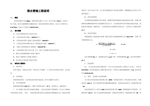
排水管线工程说明一、概况某市政道路全长3.266km, 道路等级为城市主干道, 设计车速为40km/h, 采取双向六车道。
设计在道路两侧分别铺设各设一条雨水管道和污水管道, 污水主干管管径为D400-D500; 雨水主干管管径为D500-D1800。
二、设计依据1)与业主签署某市政工程设计协议2)《室外排水设计规范》(GB50013-)()。
3)《给水排水管道工程施工及验收规范》(GB50268-)。
4)《室外给水排水和燃气热力工程抗震设计规范》(GB50032-)。
5)《城市工程管线综合计划规范》(GB50289-98)。
6)《某县城东扩新区分区计划(-)》,浙江大学城镇计划设计研究院。
7)某县文化园某路道路工程施工图设计8)某县工业路项目工程施工图设计。
9)其它相关计划及施工图设计资料三、雨污水工程设计1、标注单位管径为毫米, 管道长度为米, 坡度为‰(平面图)。
尺寸标注单位除有注明外, 均为毫米。
2、标高系统采取黄海高程系, 污水管标高均为管内底标高, 桩号为道路中心桩号。
3、设计荷载等级地面堆积荷载按10KN/m2计; 道路下重型按:超汽-20级, 轻型按:汽-10级设计。
4、本工程施工前必需对全线进行测量、定位及必需地下管线探查。
对与本工程衔接全部管道接口标高、管径、坐标位置及相关排水沟道底标高等数据进行逐一现场具体测量查对, 如有与设计不符, 应立刻书面通知设计单位做出调整。
各数据确定无误后方可开始管道施工。
5、排水管道放线在直线段均按道路桩号进行放线, 道路转变处和弧线段先确定检验井位置, 依据平面图和管综横断面图中所注沿道路纵向定位尺寸, 以及检验井桩号即可确定检验井位置, 两检验井直线连接。
道路外雨、污水检验井按平面图井位坐标定位, 支管井位于道路红线外2m处。
6、雨水管径确定依据福建省工程建设地方标准《城市及部分县城暴雨强度公式》DBJ13-52-, 查得三明市暴雨强度公式:848.0)17.12()494.01(398.3973++⨯=tLgTeq(L/s.ha)FqQψ=21tmtt+=设计重现期P=3年, 地面集水时间t1=15分钟, 管道折减系数m=2, 综合径流系数Ψ=0.5。
地下管线工程设计说明书
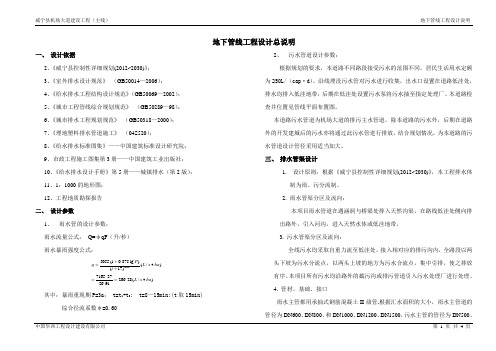
地下管线工程设计总说明一、 设计依据2、《威宁县控制性详细规划(2012~2030)》;3、《室外排水设计规范》 (GB50014—2006);4、《给水排水工程结构设计规范》(GB50069—2002);5、《城市工程管线综合规划规范》 (GB50289—98);6、《城市排水工程规划规范》 (GB50318—2000);7、《埋地塑料排水管道施工》 (04S520);8、《给水排水标准图集》——中国建筑标准设计研究院; 9、市政工程施工图集第3册——中国建筑工业出版社; 10、《给水排水设计手册》第5册——城镇排水(第2版); 11、1:1000的地形图; 12、工程地质勘探报告 二、 设计参数1、 雨水管的设计参数: 雨水流量公式: Q=φqF (升/秒) 雨水暴雨强度公式:)/(28.26691.2637.7165)/()17()lg 875.01(505595.0ha s L ha s L t P q ∙==∙++=其中:暴雨重现期P=3a ; t=t 1+t 2; t=8—15min;(t 取15min) 综合径流系数φ=0.602、 污水管道设计参数:根据规划的要求,本道路不同路段接受污水的范围不同。
居民生活用水定额为250L/(cap ·d )。
沿线埋没污水管对污水进行收集,出水口设置在道路低洼处,排水均排入低洼地带,后期在低洼处设置污水泵将污水抽至指定处理厂。
本道路检查井位置见管线平面布置图。
本道路污水管道为机场大道的排污主水管道,除本道路的污水外,后期在道路外的开发建城后的污水亦将通过此污水管进行排放,结合规划情况,为本道路的污水管道设计管径采用适当加大。
三、 排水管渠设计1. 设计原则:根据《威宁县控制性详细规划(2012~2030)》,本工程排水体制为雨、污分流制。
2. 雨水管渠分区及流向:本项目雨水管道在遇涵洞与桥梁处排入天然沟渠,在路线低洼处侧向排出路外,引入河沟,进入天然水体或低洼地带。
室外给水管线设计说明

给水管线工程施工图设计说明一、设计依据(一)设计合同依据*****公司与业主签订的设计委托书。
(二)设计规范、标准1.《室外给水设计规范》(GB50013- )2.《给水排水工程管道结构设计规范》(GB50332- )3.《给水排水工程构筑物结构设计规范》(GB50069- )4.《给排水管道工程施工及验收规范》(GB 50268- )5.《给水排水工程埋地钢管管道结构设计规范》(CECS141: )6.《埋地聚乙烯给水管道工程技术规程》(CJJ101- )7.《给水聚乙烯管材标准》(GB-T13663- )(三)设计基础资料、工程资料1.园区路网规划图;2.道路平面及纵断面图;3.道路横断面图;4.业主提供的该片区1:500地形图。
5.业主提供的其它资料二、工程概况及设计范围(一)工程概况本次设计的给水管线位于园区内,主要包括道路道路给水管线设计。
其中,道路呈走向,设计起点,设计终点,线路全长 m,规划红线宽度 m。
(二)设计范围本次设计包括道路沿线及过街处给水管线及其附属构筑物(土建部分)施工图设计。
(三)设计原则1.城市给水管道施工图设计应符合城市总体规划和片区控制性详细规划的基本要求。
2.给水管网设计应满足地区经济和社会长远发展的需要,同时注意远期发展与分期实施相结合的原则。
给水管道均按远期设计,并能适应片区建设需要,考虑分期实施的可能性。
3.新建给水管网充分考虑区域给水现状及地块建设的情况,结合地块建设规划,在给水管道断面、平面布置、高程布置上适应功能的需要和地块使用的可能性、便利性。
4.给水管网设计注意技术性与经济性相结合。
5.给水管道的平面、高程布置充分考虑各种城市管线的敷设走廊,在考虑经济性的同时预留足够的空间,为管线综合提供条件。
三、给水工程设计(一)管道布置设计1.线位布置:道路沿线给水管考虑布置在道路西(北)侧人行道上,中心距路边石0.5米,沿道路设置PE100级给水管,SDR17,公称外径为De ;过街支管公称外径为De 、De ,并加钢套管予以保护。
小学、幼儿园项目--电力管线设计说明
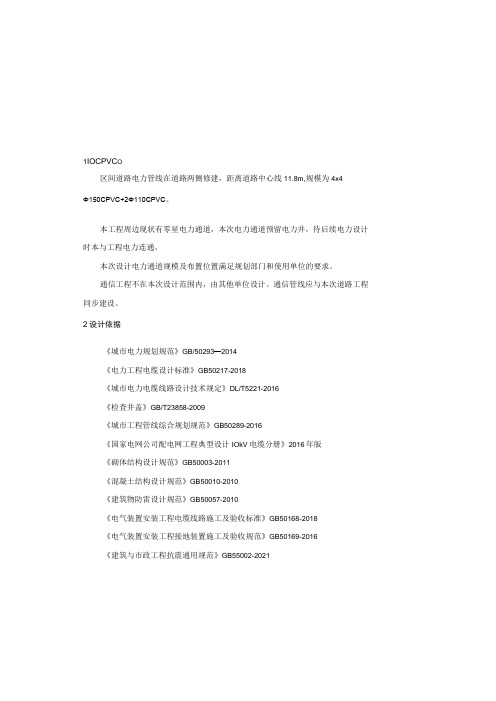
1IOCPVC O区间道路电力管线在道路两侧修建,距离道路中心线11.8m,规模为4x4Φ150CPVC+2Φ110CPVC。
本工程周边现状有零星电力通道,本次电力通道预留电力井,待后续电力设计时本与工程电力连通。
本次设计电力通道规模及布置位置满足规划部门和使用单位的要求。
通信工程不在本次设计范围内,由其他单位设计。
通信管线应与本次道路工程同步建设。
2设计依据《城市电力规划规范》GB/50293—2014《电力工程电缆设计标准》GB50217-2018《城市电力电缆线路设计技术规定》DL/T5221-2016《检查井盖》GB/T23858-2009《城市工程管线综合规划规范》GB50289-2016《国家电网公司配电网工程典型设计IOkV电缆分册》2016年版《砌体结构设计规范》GB50003-2011《混凝土结构设计规范》GB50010-2010《建筑物防雷设计规范》GB50057-2010《电气装置安装工程电缆线路施工及验收标准》GB50168-2018《电气装置安装工程接地装置施工及验收规范》GB50169-2016《建筑与市政工程抗震通用规范》GB55002-2021电力管线设计说明1设计范围新建川大附属小学、幼儿园项目勘察设计配套道路及黄堰河迁改标段,项目位于成都市双流区西航港街道,西航港新街北侧,川大路以南,黄河南路以东。
目前拟建川大附属小学、幼儿园地块正准备进行开发,目前处于设计阶段。
本项目的建设主要为地块开发提供市政基础配套设施,同时进一步完善片区市政路网。
本工程共包含东侧道路和区间道路两条市政道路。
东侧道路设计起点为与规划西航港新街交叉口,终点止于川大路。
道路设计全长615.371m,由于设计起点(与规划西航港新街交叉口处)存在拆迁障碍,故南侧实施起点暂定为K0+060,实施长度约545m。
城市次干路标准,双向6车道,三块板,道路红线宽度40m。
双向6车道,三块板,路幅划分为:3.75m(人行道)+3.5m(非机动车道)+2m(机非绿化带)+21.5m(车行道)+2m (机非绿化带)+3.5m(非机动车道)+3.75m(人行道)=4Omo区间道路设计起点为与黄河南路交叉口,终点止于拟建东侧道路。
排洪渠圳沟排水及管线综合设计说明

崇武·港边湖文体休闲公园排水与管线综合工程方案设计说明一、设计依据及内容:本工程排水管道设计以《崇武镇霞西村危房改造修建性详细规划》(辽宁省城乡建设规划设计院-2011.01)为依据。
依据主要规范规程有:1、《室外排水设计规范》GB50014-20062、《给水排水管道工程施工及验收规范》GB0268—20083、《给水排水工程管道结构设计规范》GB50332—20024、《给水排水制图标准》GB/T50106—20015、《埋地聚乙烯排水管道工程技术规程》CECS164:20046、《城市工程管线综合规划规范》(GB50289-98)。
7、《检查井盖》(GB/T23858-2009)。
受建设单位委托,本次只设计港边湖堤岸工程。
但是目前这2个工程周边尚有村落,近期暂时无法搬迁,故在设计堤岸工程同时考虑近期无法搬迁村落的排水问题,迁就现状结合《崇武镇霞西村危房改造修建性详细规划》,在港边湖边的景观道路下布置污水管,收集周边村落污水;同时结合现状村落建筑物位置,合理设计雨水管道,直接排入港边湖。
依据《崇武镇霞西村危房改造修建性详细规划》,结合现状村落部分建筑物以合流形式排出,设计纳入污水管道,故本次污水管道设计起始管段采用dn400管径,随着村落改造或搬迁,远期改为污水干管。
雨水管道考虑现状村落雨水排放与规划雨水排放进行设计的。
本排水工程设计内容主要包括雨水管道和污水管道的单项设计及这2项管线综合设计,根据《中国地震动参数区划图》,本次设计地震设防烈7度,设计基本地震加速度0.15g。
路灯、给水、弱电、电力等工程由港边湖绿化工程同一考虑。
二、雨水工程1、雨水管道设计以《崇武镇霞西村危房改造修建性详细规划》(辽宁省城乡建设规划设计院-2011.01)为依据,结合现状村落排水,对其雨水系统进行校核、优化的基础上完成本雨水工程施工图设计。
根据福建省工程建设地方标准DBJ13-52-2003,查得惠安地区暴雨强度公式:892.031(1+0.688lgTe)q= (升/秒·公倾)(t+2.055)0.534式中:Te----设计重现期,取1年q----暴雨强度(升/秒·公倾)t----降雨历时地面集水时间t1=10min,管道折减系数m=2,综合径流系数Ψ=0.65,绿地径流系数取0.2。
- 1、下载文档前请自行甄别文档内容的完整性,平台不提供额外的编辑、内容补充、找答案等附加服务。
- 2、"仅部分预览"的文档,不可在线预览部分如存在完整性等问题,可反馈申请退款(可完整预览的文档不适用该条件!)。
- 3、如文档侵犯您的权益,请联系客服反馈,我们会尽快为您处理(人工客服工作时间:9:00-18:30)。
1、本次设计依据为建筑总图、单体图纸和市政管道资料。
施工时请对照现场情况和建筑总图核对标高,并结合单体图纸施工。
2、根据单体图纸设计说明,园区最大日用水量为946.4m^U3^U,最大时用水量为91.5m^U3^U。
根据甲方提供的资料:区内雨污水分流排放,雨水经收集后就近排放至市政雨水管网,污水经化粪池处理后排放至市政污水管网。
3、总平面图中管道标高为绝对标高(黄海高程)。
管道标注DN为公称直径。
管径、井径单位为毫米。
标高和平面距离单位为米。
4、生活给水埋地管采用PE管,热熔对接连接,详见《建筑小区埋地塑料给水管道施工》(10S507)。
室外消防给水管采用内外壁热浸镀锌钢管,焊接,二次镀锌。
室外埋地用排水管采用高密度聚乙烯(HDPE)排水管,热熔连接;执行标准为《建筑排水用高密度聚乙烯(HDPE)(CJ/T250-2007)。
以上管材宜在供应商的指导下安装敷设,管道基础做法和施工沟槽回填土夯实要求详见国标图集《埋地塑料排水管道施工》(04S520)。
5、雨污水检查井采用砖砌检查井,详见02S515。
位于车行道的检查井,应采用具有足够承载力和稳定性良好的井盖与井座。
6、道路上有雨水检查井处沿道路两侧做雨水口,就近接入井内。
雨水口位置可由景观设计单位根据道路及景观做法进行设计。
人行走道及绿化的雨水收集由景观设计单位设计,就近接入雨水井。
雨水口与检查井连接管管径DN200,i=0.01坡向检查井,起点埋深0.65米,亦可根据实际情况调整埋深。
车行道下塑料管管顶覆土厚度不足800mm处,均应采取加强措施。
给水干管埋深0.6M,支管埋深0.4m 。
可根据实际情况调整标高。
埋地金属管道应采取防腐措施(两布三油)。
7、室外消火栓采用地上式,SS100-1.0型。
每栓流量按15L/s考虑。
其布置原则:消火栓间距不大于120m,保护半径不超过150m。
消火栓距路边不超过2M,距建筑物外墙不小于5M,并不大于40m。
8、倒流防止器选用带水表类型,水表型号LXLC-150。
9、管道交叉处如有标高相碰,可根据以下原则调整:
小管道让大管道。
易弯的管道让不易弯的管道。
电管在水管上。
给水管在排水管上。
压力管道让自流管道。
新设管道让已建管道。
标高无法调整时,雨污水管可做倒虹井。
个别检查井位置可根据现场情况调整。
10、给排水管道安装完毕后, 均应按国标(GB50242-2002)"建筑给水排水及采暖工程施工质量验收规范"中有关规定进行试压和试水,埋地管应试验合格并经专业技术人员鉴定后方可回填。