NI-9234说明书
Agilent N9343C手持频谱分析仪(HSA)数据手册说明书
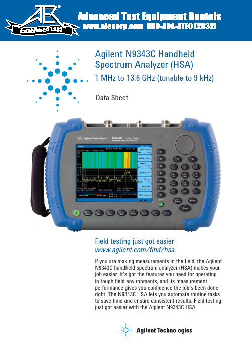
Agilent N9343C Handheld Spectrum Analyzer (HSA)1 MHz to 13.6 GHz (tunable to 9 kHz)Data SheetField testing just got easier /find/hsaIf you are making measurements in the field, the Agilent N9343C handheld spectrum analyzer (HSA) makes your job easier. It's got the features you need for operating in tough field environments, and its measurement performance gives you confidence the job's been done right. The N9343C HSA lets you automate routine tasks to save time and ensure consistent results. Field testingjust got easier with the Agilent N9343C HSA.19812Definitions and requirementsThis data sheet contains specifications and supplemental information for Agilent N9343C handheld spectrumanalyzer. The differences between specifications, typical performance, and nominal values are described as follows.Definitions"Specifications" describe the performance of parameters covered by the product warranty and apply to temperatures ranging from -10 to 50 °C, unless otherwise noted.95th percentile values indicate the breadth of the popula-tion (> 2) of performance tolerances expected to be met in 95% of the cases with a 95% confidence, for any ambient temperature in the range of 20 to 30 °C. In addition to the statistical observations of a sample of instruments, these values include the effects of the uncertainties of external calibration references. These values are not warranted. These values are updated occasionally if a significant change in the statistically observed behavior of production instruments occurs."Typical" describes additional product performanceinformation that is not covered by the product warranty. Itmeasurement uncertainty.describe product performance that is useful in the applica-warranty.Your job just got easier:• Get the features you need in a field-ready instrument.• Gain confidence in your measurements with benchtop performance in a handheld instrument.• Innovative task planner (/find/taskplanner) reduces test setup time by 95%, delivers test automation and consistency, and makes it easy to capture test results, generate reports, and share task plans with others.Conditions required to meet specificationsThe following conditions must be met for the analyzer to meet its specifications.• The analyzer is within its calibration cycle.• Under auto couple control, except when Swp Time Rule is set to Accuracy.• Any analyzer that has been stored at a temperature range inside the allowed storage range but outside the allowed operating range must be stored at an ambient temperature within the allowed operating range for at least two hours before being turned on.• The analyzer has been turned on at least 30 minutes.CertificationAgilent Technologies certifies that this product met its published specifications at the time of shipment from the factory. Agilent Technologies further certifies that its cali-bration measurements are traceable to the United States National Institute of Standards and Technology (NIST), to the extent allowed by the Institute’s calibration facility, and to the calibration facilities of other International Standards Organization (ISO) members.Specifications31. RMS detector, trace averaging > 40, 0 dB input attenuation, input terminated 50 Ω, 1 kHz resolution bandwidth, normalized to 1 Hz, 20 to 30 °C.42. Reference level only affects the display not the measurement, so trace data markers do not cause additional errors in measurement results.567* ß is the ratio of frequency deviation to symbol rate (deviation/rate).8Visit /find/taskplanner for more information.3. For efficiency and convenience, RBW is restricted to be equal to or greater than 1 kHz and VBW is restricted to be equal to RBW.9/find/N9343C /find/hsa-videosAgilent Email Updates/find/emailupdates Get the latest information on the products and applications you select. Agilent Channel Partnersw w /find/channelpartners Get the best of both worlds: Agilent’s measurement expertise and product breadth, combined with channel partner convenience.For more information on AgilentTechnologies’ products, applications orservices, please contact your local Agilentoffice. The complete list is available at:/find/contactusAmericasCanada (877) 894 4414Brazil (11) 4197 3500Mexico 01800 5064 800United States (800) 829 4444Asia PacificAustralia 1 800 629 485China 800 810 0189Hong Kong 800 938 693India 1 800 112 929Japan 0120 (421) 345Korea 080 769 0800Malaysia 1 800 888 848Singapore 180****8100Taiwan 0800 047 866Other AP Countries (65) 375 8100Europe & Middle EastBelgium 32 (0) 2 404 93 40Denmark 45 70 13 15 15Finland 358 (0) 10 855 2100France 0825 010 700**0.125€/minuteGermany 49 (0) 7031 464 6333Ireland 1890 924 204Israel 972-3-9288-504/544Italy 39 02 92 60 8484Netherlands 31 (0) 20 547 2111Spain 34 (91) 631 3300Sweden 0200-88 22 55United Kingdom 44 (0) 131 452 0200For other unlisted countries:/find/contactusRevised: June 8, 2011Product specifications and descriptionsin this document subject to changewithout notice.© Agilent Technologies, Inc. 2011Printed in USA, November 1, 20115990-7499ENAgilent Advantage Services is committedto your success throughout your equip-ment’s lifetime. To keep you competitive,we continually invest in tools andprocesses that speed up calibration andrepair and reduce your cost of ownership.You can also use Infoline Web Servicesto manage equipment and services moreeffectively. By sharing our measurementand service expertise, we help you createthe products that change our world./quality/find/advantageservices。
NI USB-9237 用户指南和产品规范说明书

安全守则
请遵循 NI USB-9237 的使用说明。
注 尽管 NI 9237 模块具有较高的认证标准,当它与 NI USB-9162 外盒配合使用时,系统
满足的标准受各组件限制。详细信息见产品规范。
高温表面 该符号表明组件表面温度较高。触摸该组件可能导致人员受伤。
注意 电源未断开或处于危险环境时,请勿断开 I/O 连线或连接器。 注意 电源未断开或处于危险环境时,请勿卸除模块。 注意 NI USB-9237 未通过用于危险环境的认证。
LabWindows/CVI Help 中的 NI-DAQmx Library 一章包括 API 概述和 NI-DAQmx 函数参考信息。点击 LabWindows/CVI Help 中的 Library Reference»NI-DAQmx Library 查看文档。
© National Instruments
数据采集设备开发虚拟仪器、数据采集和设备控制应用程序。单击开始 »
所有程序 »NationalInstruments»NI-DAQ»NI-DAQmx C Reference Help。
TEKTRONIX Card Reader 923 操作说明书

on the junction box.、The card reader is connected to receptacles on the junction box receptacle.
Using 115 V Line Power. Connect the line cord of the card reader directly into the source of 115 V line voltage.
General Interconnections Program Cards
Key Codes Preparing Program Cards Program Library
SECTION 11 SUPPLEMENTAL INFORMATION Maintenance Card Reader Problems Changing The Line Fuse Instrument Characteristics
U.S.A. and foreign Tektronix products by U.S.and foreign patents and/or pending.
covered patents
070-1296-00
472
TABLE O0F CONTENTS
SECTION 1
OPERATING INSTRUCTIONS
旦 - K o jo s2[+ 2 [x Ko o + 3 卫 P
CARD 1 0F_1
] 行 | 吉 忌 伟吊呆 肖 忍 技脚借 悦 河 传 意 河 肉倩“间 门
国 国 国 国 国 IIJ 国 国 国 国 国 国 国 国 国 国
DIO0IOI0ID
4D0 嵩 DIDIDlologloglglololololglglblolololgIDI0
国家电子NI 9924 25针DSUB到机械接线器块的用户指南和规格说明书

USER GUIDE AND SPECIFICATIONSNI 992425-Pin DSUB to Screw-Terminal Connector Block2| |NI 9924 User Guide and SpecificationsThis user guide describes the features of the National Instruments 9924 DSUB to Screw-Terminal Connector Block. Y ou can use the NI 9924 to create custom cables for C Series modules that use 25-pin DSUB connectors.Caution Do not remove the NI 9924 circuit board from the enclosure.CautionDo not supply hazardous voltages(>30V rms /42V pk /60VDC) to the NI 9924.Caution Before using the NI 9924, read the Operating Instructions and Specifications for the C Series module to ensure compliance with safety, EMC, and environmentalregulations.Connecting the NI 9924The NI 9924 provides connections for C Series 25-pin DSUB modules.Figure 1. NI 9924 T erminal AssignmentsNI 9924 User Guide and Specifications|© National Instruments|34| |NI 9924 User Guide and SpecificationsConnecting the SignalsTo wire the NI 9924, complete the following steps while referring to Figure 2.Note When using shielded wires or cable, use theSH terminal on the NI 9924 to terminate the shields.1.Loosen the captive screws and remove the top cover.2.Prepare the screw-terminal wire by stripping the insulation.Refer to the Specifications section for more information on screw-terminal wiring.3.Insert the stripped end of the wire fully into the appropriateterminal. Make sure no exposed wire extends past the screw terminal.4.Secure the connection by tightening the screw for the terminal. Refer to the Specifications section for information onscrew-terminal torque.5.Route the wire to the NI 9924 opening.6.Remove slack in the NI 9924 wiring and secure the wires or cable by threading a zip tie through the two strain relief holeson the NI9924 opening.7.Reinstall the top cover on the NI 9924 and tighten the fourcaptive screws.Figure 2. NI 9924 Parts Locator Diagram1Captive Screws 2Top Cover 3Terminals4Strain Relief Holes5JackscrewsNI 9924 User Guide and Specifications|© National Instruments|5Installing the NI 9924Connect the NI 9924 to the 25-pin DSUB connector on the moduleas shown in Figure2. Tighten the two jackscrews on the NI 9924 to hold it securely in place. Do not overtighten the jackscrews.Refer to Figure2 for the location of the jackscrews.Figure 3.Installing the NI 99246||NI 9924 User Guide and SpecificationsSpecificationsThe following specifications are typical unless otherwise noted. Maximum voltage.............................30V rms/42 V pk/60 VDC Operating temperature......................–40 to 70 °CMaximum current rating...................≤1 A per channelScrew-terminal wiring......................16 to 26 AWG copperconductor wire with 4.5 mm(0.18 in.) of insulationstripped from the end Torque for screw terminals...............0.4 N · m max(3.4lb· in. max) Weight...............................................65 g (2.29oz)NI 9924 User Guide and Specifications|© National Instruments|7© 2011–2012 National Instruments. All rights reserved.375924B-01Apr12LabVIEW, National Instruments, NI, , the National Instruments corporate logo, and the Eagle logo aretrademarks of National Instruments Corporation. Refer to the Trademark Information at /trademark s for other National Instruments trademarks. Other product and company names mentioned herein are trademarks or trade names of their respective companies. For patents covering National Instruments products/technology, refer to the appropriate location: Help»Patents in your software, the patent s .txt file on your media, or the National Instruments Patent Notice at /patent s . Refer to the Export Compliance Information at /legal/export-compliance for the National Instruments global trade compliance policy and how to obtain relevant HTS codes, ECCNs, and other import/export data.Where to Go for SupportThe National Instruments Web site is your complete resource for technical support. At /s upport you have access to everything from troubleshooting and application development self-help resources to email and phone assistance from NI Application Engineers.National Instruments corporate headquarters is located at 11500North Mopac Expressway, Austin, Texas, 78759-3504. National Instruments also has offices located around the world to help address your support needs. For telephone support in the United States, create your service request at /s upport and follow the calling instructions or dial 5127958248. For telephone support outside the United States, visit the Worldwide Offices section of /niglobal to access the branch office Web sites, which provide up-to-date contact information, support phone numbers, email addresses, and current events.。
NI-9234说明书

Sound and Vibration Data AcquisitionOverviewNI 9233 and 9234 are 4-channel dynamic signal acquisition (DSA)modules for making high-accuracy measurements from IEPE sensors.These C Series analog input modules deliver 102 dB of dynamic range and incorporate IEPE (2 mA constant current) signal conditioning for accelerometers and microphones. The four input channels simultaneously acquire at rates from 2 to 50 kHz or, with the NI 9234, up to 51.2 kS/s.In addition, the modules include built-in antialiasing filters that automatically adjust to your sampling rate. NI 9233/9234 modules are ideal for a wide variety of mobile/portable applications such as industrial machine condition monitoring and in-vehicle noise, vibration,and harshness testing.HardwareEach simultaneous signal is buffered, analog prefiltered, and sampled by a 24-bit delta-sigma analog-to-digital converter (ADC) that performs digital filtering with a cutoff frequency that automatically adjusts to yourdata rate. NI 9233/9234 modules feature a voltage range of ±5 V and a dynamic range of more than 100 dB. In addition, the modules include thecapability to read and write to transducer electronic data sheet (TEDS)Class 1 smart sensors. NI 9233/9234 modules provide ±30 V of overvoltage protection (with respect to chassis ground) for IEPE sensor connections.The NI 9234 has three software-selectable modes of measurement operation: IEPE-on with AC coupling, IEPE-off with AC coupling, and IEPE-off with DC coupling. IEPE excitation and AC coupling are not software-selectable and are always enabled for the NI 9233.NI 9233/9234 modules use a method of A/D conversion known as delta-sigma modulation. If, for example, the data rate is 25 kS/s, then each ADC actually samples its input signal at 3.2 MS/s (128 times the data rate) and produces samples that are applied to a digital filter.This filter then expands the data to 24 bits, rejects signal components greater than 12.5 kHz (the Nyquist frequency), and digitally resamples the data at the chosen data rate of 25 kS/s. This combination of analog and digital filtering provides an accurate representation of desirable signals while rejecting out-of-band signals. The built-in antialiasing filters automatically adjust themselves to discriminate between signals based on the frequency range, or bandwidth, of the signal.•24-bit resolution•102 dB dynamic range•4 simultaneous analog inputs •±5 V input range •Antialiasing filters •TEDS read/writeRecommended Software•LabVIEW•Sound and Vibration Toolkit•Sound and Vibration Measurement SuiteSupported Hardware Platforms•NI CompactDAQ •CompactRIO•Hi-Speed USB carrier •Wi-Fi/Ethernet carrierNI 9233, NI 9234NEW!Analysis Capabilities Power spectra Zoom FFTsFractional-octave analysis Vibration level measurementsWi-Fi/Ethernet Platform NEW!NI Wi-Fi data acquisition (DAQ) devices combine IEEE 802.11 wireless or Ethernet communication; direct sensor connectivity; and the flexibility of NI LabVIEW software for remote monitoring of electrical, physical, mechanical,and acoustical signals. NI Wi-Fi DAQ devices can stream data on each channel at more than 50 kS/s with 24 bits of resolution. In addition,built-in NIST-approved 128-bit AES encryption and advanced network authentication methods offer the highest commercially available network security. With the flexibility of LabVIEW graphical programming and ubiquity of 802.11 network infrastructure, NI Wi-Fi DAQ makes it easy to incorporate wireless connectivity into new or existing PC-based measurement or control systems.USB PlatformThe NI Hi-Speed USB carrier makes portable data acquisition easy. Simply plug an NI 9233/9234 module into the USB carrier and begin acquiring data. Communication to the USB carrier is over Hi-Speed USB, guaranteeing data throughput.NI CompactDAQ PlatformNI CompactDAQ delivers the simplicity of USB to sensor and electrical measurements on the benchtop, in the field, and on the production line. By combining the ease of use and low cost of a data logger with the performance and flexibility of modular instrumentation, NI CompactDAQ offers fast, accurate measurements in a small, simple, and affordable system. Flexible software options make it easy to use NI CompactDAQ to log data for simple experiments or to develop a fully automated test or control system. The modular design can measure up to 256 channels of electrical, physical, mechanical, or acoustical signals in a single system. In addition, per-channel ADCs and individually isolated modules ensure fast, accurate, and safe measurements.NI CompactRIO PlatformWhen used with the small, rugged CompactRIO embedded control and data acquisition system, NI C Series analog input modules connect directly to reconfigurable I/O (RIO) field-programmable gate array (FPGA) hardware to create high-performance embedded systems. The reconfigurable FPGA hardware within CompactRIO provides a variety of options for custom timing, triggering, synchronization, filtering, signal processing, and high-speed decision making for all C Series analog input modules. For instance, with CompactRIO, you can implement custom triggering for any analog sensor type on a per-channel basis using the flexibility and performance of the FPGA and the numerous arithmetic and comparison function blocks built into NI LabVIEW FPGA.Analysis SoftwareNI 9233/9234 modules are well-suited for noise and vibration analysis applications. The NI Sound and Vibration Measurement Suite, which specifically addresses these applications, has two components: the NI Sound and Vibration Assistant and LabVIEW analysis VIs (functions) for power spectra, frequency response (FRF), fractional octave analysis, sound-level measurements, order spectra, order maps, order extraction, sensor calibration, human vibration filters, and torsional vibration.NI Sound and Vibration AssistantThe Sound and Vibration Assistant is interactive software designed to simplify the process of acquiring and analyzing noise and vibrationsignals by offering:•A drag-and-drop, interactive analysis and acquisition environment •Rapid measurement configuration•Extended functionality through LabVIEWInteractive Analysis EnvironmentThe Sound and Vibration Assistant introduces an innovative approach to configuring your measurements using intuitive drag-and-drop steps. Combining the functionality of traditional noise and vibration analysis software with the flexibility to customize and automate routines, the Sound and Vibration Assistant can help you streamline your application.Rapid Measurement ConfigurationThere are many built-in steps available for immediate use in the Sound and Vibration Assistant. You can instantly configure a measurement and analysis application with:•Hardware I/O – generation and acquisition of signals from a variety of devices, including data acquisition devices and modular instruments •Signal processing – filtering, windowing, and averaging•Time-domain analysis – sound- and vibration-level measurements •ANSI and IEC fractional-octave analysis•Frequency-domain analysis – power spectrum, frequency response, power-in-band, peak search, and distortion•Order analysis – tachometer processing, order power spectrum, order tracking, and order extraction•Report generation – ability to drag and drop signals to Microsoft Excel or export data to Microsoft Word or UFF58 files Extended Functionality through LabVIEWReuse your measurement applications developed with the Sound and Vibration Assistant in LabVIEW by converting projects into LabVIEW block diagrams. With the LabVIEW full-featured graphical programming environment, you can further automate your application or customize your analysis.Sound and Vibration Analysis VIs for LabVIEWWith the sound and vibration analysis VIs in LabVIEW, you can develop a variety of custom audio, acoustic, and vibration applications. Functionality includes:•Full, 1/3, 1/6, 1/12, and 1/24 octave analysis with linearA, B, or C weighting•Baseband, zoom, and subset power spectrum•Peak search and power in band•Frequency response (FRF)•Filtering•Swept sine•Distortion analysis (THD, THD+N, IMD)•Noise measurements (SNR)•Human vibration weighting filters•Torsional vibration•Tachometer signal processing•Order tracking, spectrum, and order extraction•Waterfall display for power,octave, and order spectra•Shaft centerline, orbit, Bode, and polar plot format•File input and output to UFF58Figure 1. NI Sound and Vibration Assistant Performing Engine Run-Up TestRecommended HardwareThe Sound and Vibration Measurement Suite includes more than50examples that work with both DSA and multifunction data acquisition devices. For sound and vibration data acquisition, National Instruments recommends DSA devices. With 24-bit ADCs and digital-to-analog converters (DACs) and integrated antialiasing filters, DSA devices are ideal for acoustic, noise, and vibration measurements.Table 2. Additional NI Dynamic Signal Acquisition DevicesOrdering InformationNI 9234..................................................................................779680-01NI 9234 with Sound and VibrationMeasurement Suite ..............................................................779680-02NI USB-9234..........................................................................780235-01NI USB-9234 with Sound and VibrationMeasurement Suite ..............................................................780235-02NI WLS-9234........................................................................780507-01NI WLS-9234 with Sound and VibrationMeasurement Suite ..............................................................780507-02NI ENET-9234........................................................................780508-01NI ENET-9234 with Sound and VibrationMeasurement Suite ..............................................................780508-02NI 9233..................................................................................779015-01NI 9233 with Sound and VibrationMeasurement Suite ..............................................................779015-02NI USB-9233 with USB carrier..............................................779365-01NI USB-9233 with Sound and VibrationMeasurement Suite ..............................................................779366-01BUY NOW!For complete product specifications, pricing, and accessory information, call 800 813 3693 (U.S.) or go to /soundandvibration.There are numerous system requirements to consider when selecting data acquisition hardware for measuring or generating sound and vibration signals. From IEPE signal conditioning for accelerometers and microphones to high dynamic range (up to 118 dB) and multichannel synchronization (up to 13,000 channels), National Instruments offers a wide range of hardware products for your applications.NI 9233 Specifications>>For complete specifications, see the NI 9233 Operating Instructions and Specifications at /manuals.The following specifications are typical for the range 0 to 60 °C unless otherwise noted.Input CharacteristicsNumber of channels............................ 4 analog inputADC resolution....................................24 bitsType of ADC .......................................Delta-sigma(with analog prefiltering) Data rate (fs) Minimum......................................... 2 kS/s Maximum........................................50 kS/sMaster timebase (internal) Frequency........................................12.8 MHz Accuracy.........................................±100 ppm maxInput coupling.................................ACAC cutoff frequency-3 dB................................................0.5 Hz typ-0.1 dB............................................. 4.2 Hz maxAC voltage full-scale range Typical............................................. 5.4 V pk Minimum......................................... 5 V pk Maximum........................................ 5.8 V pkCommon-mode voltage(AI- to earth ground).......................±2 VIEPE excitation current Minimum......................................... 2.0 mA Typical............................................. 2.2 mAIEPE compliance voltage................19 V maxOvervoltage protection (with respect to chassis ground)For an IEPE sensor connectedto AI+ and AI-.................................±30 VFor a low-impedance source connectedto AI+ and AI-.................................-6 to 30 VNI 9234 Specifications>>For complete specifications, see the NI 9234 Operating Instructions and Specifications at /manuals.The following specifications are typical for the range 0 to 60 °C unless otherwise noted.Input CharacteristicsNumber of channels............................ 4 analog inputADC resolution....................................24 bitsType of ADC........................................Delta-sigma(with analog prefiltering) Data rate (fs) Minimum......................................... 1.65 kS/s Maximum........................................51.2 kS/sMaster timebase (internal) Frequency........................................13.1 MHz Accuracy.........................................±50 ppm maxInput coupling.....................................Software-selectable AC/DC AC cutoff frequency-3 dB................................................0.5 Hz typ-0.1 dB............................................. 4.6 Hz maxAC voltage full-scale range Typical............................................. 5.1 V pk Minimum......................................... 5 V pk Maximum........................................ 5.2 V pkCommon-mode voltage(AI- to earth ground).......................±2 VIEPE excitation current Minimum......................................... 2.0 mA Typical............................................. 2.1 mAIEPE compliance voltage..................... 19 V maxOvervoltage protection (with respect to chassis ground)For an IEPE sensor connectedto AI+ and AI-.................................±30 VFor a low-impedance source connectedto AI+ and AI-.................................-6 to 30 VNI Services and SupportNI has the services and support to meet your needs around the globe and through the application life cycle – from planning and development through deployment and ongoing maintenance. We offer services and service levels to meet customer requirements in research,design, validation, and manufacturing. Visit /services .Training and CertificationNI training is the fastest, most certain route to productivity with our products. NI training can shorten your learning curve, save development time, and reduce maintenance costs over the application life cycle. We schedule instructor-led courses in cities worldwide, or we can hold a course at your facility. We also offer a professional certification program that identifies individuals who have high levels of skill and knowledge on using NI products. Visit /training .Professional ServicesOur NI Professional Services team is composed of NI applications and systems engineers and a worldwide National Instruments Alliance Partner program of more than 600 independent consultants andintegrators. Services range from start-up assistance to turnkey system integration. Visit /alliance .OEM SupportWe offer design-in consulting and product integration assistance if you want to use our products for OEM applications. For information about special pricing and services for OEM customers, visit /oem .Local Sales and Technical SupportIn offices worldwide, our staff is local to the country, giving you access to engineers who speak your language. NI delivers industry-leading technical support through online knowledge bases, our applications engineers, and access to 14,000 measurement and automationprofessionals within NI Developer Exchange forums. Find immediate answers to your questions at /support .We also offer service programs that provide automatic upgrades to your application development environment and higher levels of technical support. Visit /ssp .Hardware ServicesNI Factory Installation ServicesNI Factory Installation Services (FIS) is the fastest and easiest way to use your PXI or PXI/SCXI combination systems right out of the box.Trained NI technicians install the software and hardware and configure the system to your specifications. NI extends the standard warranty by one year on hardware components (controllers, chassis, modules)purchased with FIS. To use FIS, simply configure your system online with /pxiadvisor .Calibration ServicesNI recognizes the need to maintain properly calibrated devices for high-accuracy measurements. We provide manual calibration procedures, services to recalibrate your products, and automated calibration software specifically designed for use by metrology laboratories. Visit /calibration .Repair and Extended WarrantyNI provides complete repair services for our products. Express repair and advance replacement services are also available. We offerextended warranties to help you meet project life-cycle requirements. Visit /services .SERVICE NEEDSM A I NT AI N P LA ND EV E L O PD EP L O YNational Instruments • info@ •800 813 3693*351620A-01*351620-012008-9871-101-D。
NI 9238 4通道模拟输入模块说明书
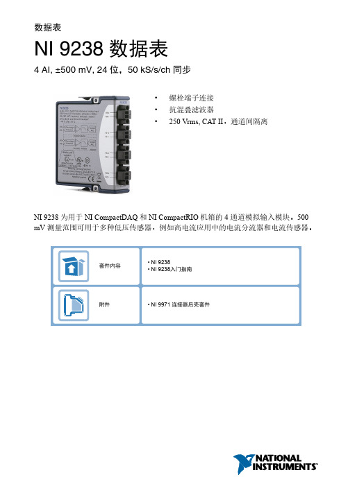
数据表NI 9238数据表4 AI, ±500 mV, 24位,50 kS/s/ch同步•螺栓端子连接•抗混叠滤波器•250 Vrms, CAT II,通道间隔离NI 9238为用于NI CompactDAQ和NI CompactRIO机箱的4通道模拟输入模块。
500 mV测量范围可用于多种低压传感器,例如高电流应用中的电流分流器和电流传感器。
NI C 系列概述NI 提供超过100种C 系列模块,用于测量、控制以及通信应用程序。
C 系列模块可连接任意传感器或总线,并允许进行高精度测量,以满足高级数据采集及控制应用程序的需求。
•与测量相关的信号调理,可连接一组传感器和信号•隔离选项包括组间、通道间以及通道对地•温度范围为-40 °C ~70 °C ,满足各种应用程序和环境需要•热插拔CompactRIO 和CompactDAQ 平台同时支持大部分C 系列模块,用户无需修改就可将模块在两个平台间转换。
CompactRIOCompactRIO 将开放嵌入式架构与小巧、坚固以及C 系列模块进行了完美融合,是一种由NI LabVIEW 驱动的可重配置I/O (RIO )架构。
每个系统包含一个FPGA ,用于自定义定时、触发以及处理一系列可用的模块化I/O ,可满足任何嵌入式应用程序的需求。
2 | | NI 9238数据表CompactDAQCompactDAQ是一种便携、耐用的数据采集平台,其模块化I/O集成了连接、数据采集以及信号调理功能,可直接接入任意传感器或信号。
配合LabVIEW使用CompactDAQ,用户可轻松地定义如何采集、分析、可视化以及管理测量数据。
软件LabVIEW专业版开发系统- 用于Windows•使用高级软件工具进行大型项目开发•通过DAQ助手和仪器I/O助手自动生成代码•使用高级测量分析和数字信号处理•利用DLL、ActiveX和.NET对象的开放式连接•生成DLL、可执行程序以及MSI安装程序NI LabVIEW FPGA模块•设计用于NI RIO硬件的FPGA应用程序•使用和台式及实时应用程序一样的图形化环境进行编程•以最高为300 MHz的循环速率执行控制算法•实现自定义定时和触发逻辑、数字协议以及DSP算法•集成现有HDL代码和第三方IP(包括Xilinx IP生成器函数)•作为LabVIEW Embedded Control and Monitoring Suite的一部分购买NI LabVIEW Real-Time模块•使用LabVIEW图形化编程设计确定性实时应用程序•下载至专有NI或第三方硬件,获得可靠的执行及多种I/O选择•利用内置的PID控制、信号处理以及分析函数•自动利用多核CPU或手动设置处理器关联•利用实时操作系统、开发和调试支持以及板卡支持•独立购买,或作为LabVIEW套件的一部分购买NI 9238数据表 |© National Instruments|3NI 9238 电路•每个通道的输入信号经缓冲、调理后,由模数转换器(ADC)对其采样。
NI 9237 四通道同时桥接模块数据手册说明书

DAT ASHEETNI 92374 AI, ±25 mV/V, 24 Bit, 50 kS/s/ch Simultaneous, Bridge Completion• 4 channels, 50 kS/s per channel simultaneous AI•±25 mV/V input range, 24-bit resolution•Programmable half- and full-bridge completionwith up to 10 V internal excitation•60 VDC, Category I bank isolation•RJ50 or D-SUB connectivity options•-40 °C to 70 °C operating range, 5 g vibration,50 g shockThe NI 9237 simultaneous bridge module for use with CompactDAQ and CompactRIO contains all the signal conditioning required to power and measure up to four bridge-based sensors simultaneously. The four RJ50 jacks provide direct connectivity to most torque or load cells and offer custom cable solutions with minimal tools. The high sampling rate and bandwidth of the NI 9237 offer a high-quality, high-speed strain or load measurement system with zero interchannel phase delay. With 60 VDC isolation and 1,000 Vrms transient isolation, the NI 9237 has high-common-mode noise rejection and increased safety for both the operator and test system.The NI 9237 can perform offset/null as well as shunt calibration and remote sense, making the module the best choice for strain and bridge measurements.The NI 9944 and NI 9945 are accessories for use with quarter-bridge sensors. These accessories have a female RJ50 connector on one end and screw terminals on the other end.C SERIES SIMULTANEOUS BRIDGE MODULE COMPARISONModel ChannelsSample Rate Resolution Connectivity Simultaneous Supported Bridges NI 9218NI 9219NI 9235NI 9236NI 923751.2 kS/s/ch 100 S/s/ch 10 kS/s/ch 10 kS/s/ch 50 kS/s/ch24 bits 24 bits 24 bits 24 bits 24 bitsQuarter, Half, Full Quarter, Half, Full 120 Ω Quarter Bridge 350 Ω Quarter Bridge Quarter, Half, FullLEMO,9-pin DSUB Spring Terminal Spring T erminal Spring T erminal RJ-50,DSUB24884NI C Series OverviewNI provides more than 100 C Series modules for measurement, control, and communication applications. C Series modules can connect to any sensor or bus and allow for high-accuracy measurements that meet the demands of advanced data acquisition and control applications.•Measurement-specific signal conditioning that connects to an array of sensors and signals •Isolation options such as bank-to-bank, channel-to-channel, and channel-to-earth ground •-40 °C to 70 °C temperature range to meet a variety of application and environmentalneeds •Hot-swappable The majority of C Series modules are supported in both CompactRIO and CompactDAQ platforms and you can move modules from one platform to the other with no modification.2 | | NI 9237 DatasheetCompactRIOCompactRIO combines an open-embedded architecturewith small size, extreme ruggedness, and C Seriesmodules in a platform powered by the NI LabVIEWreconfigurable I/O (RIO) architecture. Each systemcontains an FPGA for custom timing, triggering, andprocessing with a wide array of available modular I/O tomeet any embedded application requirement. CompactDAQCompactDAQ is a portable, rugged data acquisition platformthat integrates connectivity, data acquisition, and signalconditioning into modular I/O for directly interfacing to anysensor or signal. Using CompactDAQ with LabVIEW, youcan easily customize how you acquire, analyze, visualize,and manage your measurement data.SoftwareLabVIEW Professional Development System for Windows•Use advanced software tools for large project development•Generate code automatically using DAQ Assistant and InstrumentI/O Assistant•Use advanced measurement analysis and digital signal processing•Take advantage of open connectivity with DLLs, ActiveX,and .NET objects•Build DLLs, executables, and MSI installersNI LabVIEW FPGA Module•Design FPGA applications for NI RIO hardware•Program with the same graphical environment used for desktop andreal-time applications•Execute control algorithms with loop rates up to 300 MHz•Implement custom timing and triggering logic, digital protocols, andDSP algorithms•Incorporate existing HDL code and third-party IP including Xilinx IPgenerator functions•Purchase as part of the LabVIEW Embedded Control and MonitoringSuiteNI 9237 Datasheet| © National Instruments| 3NI LabVIEW Real-Time Module•Design deterministic real-time applications with LabVIEWgraphical programming•Download to dedicated NI or third-party hardware for reliableexecution and a wide selection of I/O•Take advantage of built-in PID control, signal processing, andanalysis functions•Automatically take advantage of multicore CPUs or setprocessor affinity manually•Take advantage of real-time OS, development and debuggingsupport, and board support•Purchase individually or as part of a LabVIEW suiteCircuitryEach channel on the NI 9237 has an independent 24-bit ADC and an input amplifier that enable you to sample signals from all four channels simultaneously.The NI 9237 is isolated from earth ground. However, the individual channels are not isolated from each other. The EX+, EX-, and T- signals are common among all channels. You can connect the NI 9237 to a device that is biased at any voltage within the NI 9237 rejection range of earth ground.Figure 1. Input Circuitry for One Channel of the NI 9237Connection Options to Correct for Resistance Errors Wiring resistance can create errors in bridge circuits. The NI 9237 provides two mechanisms to correct for these errors: remote sensing and shunt calibration.Remote SensingRemote sensing continuously and automatically corrects for errors in excitation leads, and generally is most appropriate for half- and full-bridge sensors.Long wire and small gauge wire have greater resistance, which can result in gain error. The resistance in the wires that connect the excitation voltage to the bridge causes a voltage drop, 4| | NI 9237 Datasheetwhich is a source of gain error. The NI 9237 includes remote sensing to compensate for this gain error. Connect remote sense wires to the points where the excitation voltage wires connect to the bridge circuit. Refer to the following figure for an illustration of how to connect remote sense wires to the NI 9237.Figure 2. Connecting Remote Sense Wires to the NI 9237RRThe actual bridge excitation voltage is smaller than the voltage at the EX+ and EX- leads. If you do not use remote sensing of the actual bridge voltage, the resulting gain error is:BB BBB for half‐bridge sensors and2⋅BBBBB for full‐bridge sensors.If you connect the remote sense signals directly to the bridge resistors, the NI 9237 senses the actual bridge voltage and eliminates the gain errors caused by the resistance of the EX+ and EX- leads.Shunt CalibrationShunt calibration can correct for errors from the resistance of both the excitation wiring and wiring in the individual resistors of the bridge. Remote sensing corrects for resistances from the EX pins on the NI 9237 to the sensor, and shunt calibration corrects for these errors and for errors caused by wire resistance within an arm of the bridge. Shunt calibration is most useful with quarter-bridge sensors because there may be significant resistance in the wiring to the active resistor in the bridge.The NI 9237 shunt calibration circuitry consists of a precision resistor and a software-controlled switch. Refer to the software help for information about enabling the shunt calibration switch for the NI 9237.Shunt calibration involves simulating the input of strain by changing the resistance of an arm in the bridge by some known amount. This is accomplished by shunting, or connecting, a large resistor of known value across one arm of the bridge, creating a known strain-induced change in resistance. You can then measure the output of the bridge and compare it to the expected voltage value. You can use the results to correct gain errors in the entire measurement path, or to simply verify general operation to gain confidence in the setup.NI 9237 Datasheet| © National Instruments| 5Use a stable signal, which is typically the unloaded state of the sensor, first with the shunt calibration switch off and then again with the switch on. The difference in these two measurements provides an indication of the gain errors from wiring resistances. You can design the software application to correct subsequent readings for this gain error.Excitation VoltagesYou can program the NI 9237 to supply 2.5 V , 3.3 V , 5 V , or 10 V of excitation voltage. Themaximum excitation power for internal excitation is 150 mW.Note Unless you supply external excitation voltage, NI recommends that you setthe excitation voltage to a value that keeps the total power below 150 mW. The NI 9237 automatically reduces internal excitation voltages as needed to stay below 150 mW total power.Use the following equation to calculate the power of a single bridge:=B 2where R is the total resistance of the bridge.For a quarter or half bridge, R is equal to two times the resistance of each element. For a full bridge, R is equal to the resistance of each element.The 150 mW limit allows you to power half and full bridges as follows:•Four 350 Ω half bridges at 5.0 V •Four 350 Ω full bridges at 3.3 V •Four 120 Ω half bridges at 2.5 VExternal ExcitationYou can connect an external excitation voltage source to the NI 9237 if you need an excitation voltage that causes more than 150 mW to dissipate across all the bridges.Figure 3. Connecting an External Excitation Voltage Source to the NI 9237External Excitation VoltageSourceExternal Excitation Voltage SourceNote For the NI 9237 with RJ-50, use the two EX+ and EX- terminals on the four-terminal external excitation voltage connector to connect one external excitation source.You can use the additional EX+ and EX- terminals on the connector to wire multiple NI 9237modules together in a daisy chain.6 | | NI 9237 DatasheetFilteringThe NI 9237 uses a combination of analog and digital filtering to provide an accurate representation of in-band signals and reject out-of-band signals. The filters discriminatebetween signals based on the frequency range, or bandwidth, of the signal. The three important bandwidths to consider are the passband, the stopband, and the anti-imaging bandwidth.The NI 9237 represents signals within the passband, as quantified primarily by passband ripple and phase nonlinearity. All signals that appear in the alias-free bandwidth are either unaliased signals or signals that have been filtered by at least the amount of the stopband rejection.PassbandThe signals within the passband have frequency-dependent gain or attenuation. The small amount of variation in gain with respect to frequency is called the passband flatness. Thedigital filters of the NI 9237 adjust the frequency range of the passband to match the data rate.Therefore, the amount of gain or attenuation at a given frequency depends on the data rate.Figure 4. Typical Passband Flatness for the NI 9237Frequency/Data Rate0.50.40.0250.000–0.025–0.0500.30.20.10G a i n (d B)StopbandThe filter significantly attenuates all signals above the stopband frequency. The primary goal of the filter is to prevent aliasing. Therefore, the stopband frequency scales precisely with the data rate. The stopband rejection is the minimum amount of attenuation applied by the filter to all signals with frequencies within the stopband.Alias-Free BandwidthAny signals that appear in the alias-free bandwidth are not aliased artifacts of signals at a higher frequency. The alias-free bandwidth is defined by the ability of the filter to reject frequencies above the stopband frequency. The alias-free bandwidth is equal to the data rate minus the stopband frequency.NI 9237 Datasheet | © National Instruments | 7Data RatesThe frequency of a master timebase (f M) controls the data rate (f s) of the NI 9237. The NI 9237 includes an internal master timebase with a frequency of 12.8 MHz, but the module also can accept an external master timebase or export its own master timebase. To synchronize the data rate of an NI 9237 with other modules that use master timebases to control sampling, all of the modules must share a single master timebase source.The following equation provides the available data rates of the NI 9237:=÷256where n is any integer from 1 to 31.However, the data rate must remain within the appropriate data rate range. When using the internal master timebase of 12.8 MHz, the result is data rates of 50 kS/s, 25 kS/s, 16.667 kS/s, and so on down to 1.613 kS/s depending on the value of n. When using an external timebase with a frequency other than 12.8 MHz, the NI 9237 has a different set of data rates.Note The NI 9151 R Series Expansion chassis does not support sharing timebasesbetween modules.NI 9237 SpecificationsThe following specifications are typical for the range -40 °C to 70 °C unless otherwise noted.Caution Do not operate the NI 9237 in a manner not specified in this document.Product misuse can result in a hazard. You can compromise the safety protectionbuilt into the product if the product is damaged in any way. If the product isdamaged, return it to NI for repair.Input CharacteristicsNumber of channels 4 analog input channelsBridge completionHalf and Full InternalQuarter ExternalADC resolution24 bitsType of ADC Delta-Sigma (with analog prefiltering) Sampling mode Simultaneous8| | NI 9237 DatasheetInternal master timebase (ƒM)Frequency12.8 MHzAccuracy±100 ppm maximumData rate range (ƒs) using internal master timebaseMinimum 1.613 kS/sMaximum50 kS/sData rate range (ƒs) using external master timebaseMinimum391 S/sMaximum51.36 kS/sData rates (ƒs)(ƒM ÷ 256) ÷ n, where n = 1, 2, …, 31 Typical input range±25 mV/VScaling coefficient 2.9802 nV/V per LSBOvervoltage protection between any two pins±30 VGain drift10 ppm/°C maximumOffset drift2.5 V excitation0.6 µV/V per °C3.3 V excitation0.5 µV/V per °C5 V excitation0.3 µV/V per °C10 V excitation0.2 µV/V per °C1Before offset null or shunt calibration.2Applies at a data rate of 50 kS/s. Lower data rates can have up to 0.20% of reading additional gain error.3Range equals 25 mV/V.4Uncalibrated accuracy refers to the accuracy achieved when acquiring data in raw or unscaledmodes and in which calibration constants that are stored in the module are not applied to the data.NI 9237 Datasheet| © National Instruments| 9Half-bridge completionTolerance±1200 µV/V maximumDrift 1.5 µV/V per °CTable 2. Channel-to-Channel Matching (Calibrated)Phase nonlinearityƒin = 0 to 1 kHz<0.001°ƒin = 0 to 20 kHz±0.1°Input delay(40 + 5/512)/ƒs + 4.5 µs PassbandFrequency0.45 · ƒsFlatness0.1 dB maximum StopbandFrequency0.55 · ƒsRejection100 dBAlias-free bandwidth0.45 · ƒsOversample rate64 · ƒsRejection at oversample rate5ƒs = 10 kS/s60 dB @ 640 kHzƒs = 50 kS/s*********** Common-mode voltage,all signals to earth ground±60 VDCCommon-mode voltage range, with respect to EX-±1 V from the midpoint of the excitation voltage5Rejection by analog prefilter of signal frequencies at oversample rate. 10| | NI 9237 DatasheetCMRRRelative to earth ground6 (ƒin = 0 to 60140 dBHz)Relative to EX– (ƒin = 0 to 1 kHz)85 dBSFDR (1 kHz, –60 dBFS)115 dBTotal Harmonic Distortion (THD)1 kHz, –20 dBFS–95 dB8 kHz, –20 dBFS–95 dBExcitation noise100 µVrmsCrosstalk (not including cable effects)ƒin = 1 kHz110 dBƒin = 10 kHz100 dBExcitationInternal voltage 2.5 V, 3.3 V, 5.0 V, 10.0 VInternal power150 mW maximumExternal voltage 2 V to 10 VShunt calibrationResistance100 kΩ6Measured with a balanced cable on the NI 9237 with RJ-50 and with no cable on theNI 9237 with DSUB. Shielded cables that are not twisted-pair may be significantly unbalanced, which can impact CMRR performance. To improve the balance of shielded cables, NI recommends twisting together the AI+/AI– pair, the RS+/RS– pair, and the EX+/EX– pair.NI 9237 Datasheet| © National Instruments| 11Resistor accuracy25 °C±110 Ω– 40 °C to 70 °C±200 ΩMTBFNI 9237 with RJ-50603,359 hours at 25 °C; Bellcore Issue 2,Method 1, Case 3, Limited Part Stress Method NI 9237 with DSUB704,148 hours at 25 °C; Bellcore Issue 2,Method 1, Case 3, Limited Part Stress Method Power RequirementsPower consumption from chassisActive mode740 mW maximumSleep mode25 µW maximumThermal dissipation (at 70 °C)Active mode740 mW maximumSleep mode25 µW maximumPhysical CharacteristicsTip For two-dimensional drawings and three-dimensional models of the C Seriesmodule and connectors, visit /dimensions and search by module number.Connect only voltages that are within the following limits.Between any two pins±30 V maximumIsolation, channel-to-channel NoneIsolation, channel-to-earth groundUp to 3,000 mContinuous60 VDC, Measurement Category IWithstand1,000 Vrms, verified by a 5 s dielectricwithstand testUp to 5,000 mContinuous60 VDC, Measurement Category IWithstand860 Vrms, verified by a 5 s dielectricwithstand test12| | NI 9237 DatasheetMeasurement Category I is for measurements performed on circuits not directly connected to the electrical distribution system referred to as MAINS voltage. MAINS is a hazardous live electrical supply system that powers equipment. This category is for measurements of voltages from specially protected secondary circuits. Such voltage measurements include signal levels, special equipment, limited-energy parts of equipment, circuits powered by regulated low-voltage sources, and electronics.Caution Do not connect the NI 9237 to signals or use for measurements withinMeasurement Categories II, III, or IV.Note Measurement Categories CAT I and CAT O are equivalent. These test andmeasurement circuits are not intended for direct connection to the MAINS buildinginstallations of Measurement Categories CAT II, CAT III, or CAT IV. Hazardous LocationsU.S. (UL)Class I, Division 2, Groups A, B, C, D, T4;Class I, Zone 2, AEx nA IIC T4Canada (C-UL)Class I, Division 2, Groups A, B, C, D, T4;Class I, Zone 2, Ex nA IIC T4Europe (ATEX) and International (IECEx)Ex nA IIC T4 GcSafety and Hazardous Locations StandardsThis product is designed to meet the requirements of the following electrical equipment safety standards for measurement, control, and laboratory use:•IEC 61010-1, EN 61010-1•UL 61010-1, CSA 61010-1•EN 60079-0:2012, EN 60079-15:2010•IEC 60079-0: Ed 6, IEC 60079-15; Ed 4•UL 60079-0; Ed 5, UL 60079-15; Ed 3•CSA 60079-0:2011, CSA 60079-15:2012Note For UL and other safety certifications, refer to the product label or the OnlineProduct Certification section.Electromagnetic CompatibilityThis product meets the requirements of the following EMC standards for sensitive electrical equipment for measurement, control, and laboratory use:•EN 61326-2-1 (IEC 61326-2-1): Class A emissions; Industrial immunity•EN 55011 (CISPR 11): Group 1, Class A emissions•AS/NZS CISPR 11: Group 1, Class A emissionsNI 9237 Datasheet| © National Instruments| 13•FCC 47 CFR Part 15B: Class A emissions•ICES-001: Class A emissionsNote In the United States (per FCC 47 CFR), Class A equipment is intended foruse in commercial, light-industrial, and heavy-industrial locations. In Europe,Canada, Australia and New Zealand (per CISPR 11) Class A equipment is intendedfor use only in heavy-industrial locations.Note Group 1 equipment (per CISPR 11) is any industrial, scientific, or medicalequipment that does not intentionally generate radio frequency energy for thetreatment of material or inspection/analysis purposes.Note For EMC declarations and certifications, and additional information, refer tothe Online Product Certification section.CE ComplianceThis product meets the essential requirements of applicable European Directives, as follows:•2014/35/EU; Low-V oltage Directive (safety)•2014/30/EU; Electromagnetic Compatibility Directive (EMC)•94/9/EC; Potentially Explosive Atmospheres (ATEX)Online Product CertificationRefer to the product Declaration of Conformity (DoC) for additional regulatory compliance information. To obtain product certifications and the DoC for this product, visit / certification, search by model number or product line, and click the appropriate link in the Certification column.Shock and VibrationTo meet these specifications, you must panel mount the system.Operating vibrationRandom (IEC 60068-2-64) 5 g rms, 10 Hz to 500 HzSinusoidal (IEC 60068-2-6) 5 g, 10 Hz to 500 HzOperating shock (IEC 60068-2-27)30 g, 11 ms half sine; 50 g, 3 ms half sine;18 shocks at 6 orientations14| | NI 9237 DatasheetEnvironmentalRefer to the manual for the chassis you are using for more information about meeting these specifications.Operating temperature-40 °C to 70 °C(IEC 60068-2-1, IEC 60068-2-2)-40 °C to 85 °CStorage temperature(IEC 60068-2-1, IEC 60068-2-2)Ingress ProtectionNI 9237 with RJ-50IP30NI 9237 with DSUB IP40Operating humidity (IEC 60068-2-78)10% RH to 90% RH, noncondensing Storage humidity (IEC 60068-2-78)5% RH to 95% RH, noncondensing Pollution Degree2Maximum altitude5,000 mIndoor use only.Environmental ManagementNI is committed to designing and manufacturing products in an environmentally responsible manner. NI recognizes that eliminating certain hazardous substances from our products is beneficial to the environment and to NI customers.For additional environmental information, refer to the Minimize Our Environmental Impact web page at /environment. This page contains the environmental regulations and directives with which NI complies, as well as other environmental information not included in this document.Waste Electrical and Electronic Equipment (WEEE) EU Customers At the end of the product life cycle, all NI products must bedisposed of according to local laws and regulations. For more information abouthow to recycle NI products in your region, visit /environment/weee.电子信息产品污染控制管理办法(中国RoHS)中国客户National Instruments符合中国电子信息产品中限制使用某些有害物质指令(RoHS)。
噪音测试
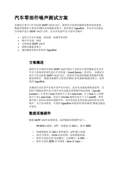
汽车零部件噪声测试方案本测试方案专门针对标准GMW 14155设计,提供符合标准的数据采集和处理系统。
数据采集硬件主要采用NI C系列数据采集卡,软件使用SignalPad。
不仅可以采集运行时噪声进行GMW 14155分析,还可评估消声室/半消声室噪声。
•适用于汽车后视镜、雨刮器、座椅等零部件•噪声声压级、响度•支持标准GMW 14155•便携式数据采集卡•通用数据采集分析软件SignalPad方案概述通用汽车全球技术规范GMW 14155规定了实验室中使用测量麦克风对汽车子系统或零部件进行声音质量(Sound Quality)的评估。
本测试方案专门针对标准GMW 14155设计,提供符合标准的数据采集硬件和数据处理软件。
数据采集硬件主要采用NI C系列9234数据采集卡,软件使用SignalPad。
本测试应该在消声室或半消声室中进行。
除非有其他标准特别说明,否则用于测量的消声室/半消声室应该满足背景噪声特征响度(SpecificLoudness)在0到5 bark范围内小于0.2 sones/bark,在5 bark以上的频段小于0.1 sones/bark。
其总计Zwicker响度应该小于1.2 soneGF。
背景噪声除了房间本身的环境噪声外,还应该包括支持设备运转时所发出的噪声。
关于此项要求,可使用SignalPad所提供的“特征响度”测量功能进行验证。
数据采集硬件根据GMW 14155标准要求,选用数据采集硬件如下:NI 9234 4通道,±5V,每通道51.2KS/s,24位IEPE▪每通道最高51.2KS/s采样速率;±5V输入范围;▪24位分辨率;102db动态范围;抗混叠滤波器;▪软件可选的交流/直流耦合;交流耦合(0.5HZ);▪软件可选的IEPE信号调理(0mA或2mA);传感器及信号调理产品编号产品描述产品要求1 自由场麦克风要求使用12.7mm(1/2英寸)自由场麦克风2 麦克风校准器测试分析软件本系统配备了SignalPad测控软件,可完成通道配置、参数设置、数据采集、显示与存储、频率响应函数计算、共振频率自动检测、数据回放等任务。
- 1、下载文档前请自行甄别文档内容的完整性,平台不提供额外的编辑、内容补充、找答案等附加服务。
- 2、"仅部分预览"的文档,不可在线预览部分如存在完整性等问题,可反馈申请退款(可完整预览的文档不适用该条件!)。
- 3、如文档侵犯您的权益,请联系客服反馈,我们会尽快为您处理(人工客服工作时间:9:00-18:30)。
Sound and Vibration Data AcquisitionOverviewNI 9233 and 9234 are 4-channel dynamic signal acquisition (DSA)modules for making high-accuracy measurements from IEPE sensors.These C Series analog input modules deliver 102 dB of dynamic range and incorporate IEPE (2 mA constant current) signal conditioning for accelerometers and microphones. The four input channels simultaneously acquire at rates from 2 to 50 kHz or, with the NI 9234, up to 51.2 kS/s.In addition, the modules include built-in antialiasing filters that automatically adjust to your sampling rate. NI 9233/9234 modules are ideal for a wide variety of mobile/portable applications such as industrial machine condition monitoring and in-vehicle noise, vibration,and harshness testing.HardwareEach simultaneous signal is buffered, analog prefiltered, and sampled by a 24-bit delta-sigma analog-to-digital converter (ADC) that performs digital filtering with a cutoff frequency that automatically adjusts to yourdata rate. NI 9233/9234 modules feature a voltage range of ±5 V and a dynamic range of more than 100 dB. In addition, the modules include thecapability to read and write to transducer electronic data sheet (TEDS)Class 1 smart sensors. NI 9233/9234 modules provide ±30 V of overvoltage protection (with respect to chassis ground) for IEPE sensor connections.The NI 9234 has three software-selectable modes of measurement operation: IEPE-on with AC coupling, IEPE-off with AC coupling, and IEPE-off with DC coupling. IEPE excitation and AC coupling are not software-selectable and are always enabled for the NI 9233.NI 9233/9234 modules use a method of A/D conversion known as delta-sigma modulation. If, for example, the data rate is 25 kS/s, then each ADC actually samples its input signal at 3.2 MS/s (128 times the data rate) and produces samples that are applied to a digital filter.This filter then expands the data to 24 bits, rejects signal components greater than 12.5 kHz (the Nyquist frequency), and digitally resamples the data at the chosen data rate of 25 kS/s. This combination of analog and digital filtering provides an accurate representation of desirable signals while rejecting out-of-band signals. The built-in antialiasing filters automatically adjust themselves to discriminate between signals based on the frequency range, or bandwidth, of the signal.•24-bit resolution•102 dB dynamic range•4 simultaneous analog inputs •±5 V input range •Antialiasing filters •TEDS read/writeRecommended Software•LabVIEW•Sound and Vibration Toolkit•Sound and Vibration Measurement SuiteSupported Hardware Platforms•NI CompactDAQ •CompactRIO•Hi-Speed USB carrier •Wi-Fi/Ethernet carrierNI 9233, NI 9234NEW!Analysis Capabilities Power spectra Zoom FFTsFractional-octave analysis Vibration level measurementsWi-Fi/Ethernet Platform NEW!NI Wi-Fi data acquisition (DAQ) devices combine IEEE 802.11 wireless or Ethernet communication; direct sensor connectivity; and the flexibility of NI LabVIEW software for remote monitoring of electrical, physical, mechanical,and acoustical signals. NI Wi-Fi DAQ devices can stream data on each channel at more than 50 kS/s with 24 bits of resolution. In addition,built-in NIST-approved 128-bit AES encryption and advanced network authentication methods offer the highest commercially available network security. With the flexibility of LabVIEW graphical programming and ubiquity of 802.11 network infrastructure, NI Wi-Fi DAQ makes it easy to incorporate wireless connectivity into new or existing PC-based measurement or control systems.USB PlatformThe NI Hi-Speed USB carrier makes portable data acquisition easy. Simply plug an NI 9233/9234 module into the USB carrier and begin acquiring data. Communication to the USB carrier is over Hi-Speed USB, guaranteeing data throughput.NI CompactDAQ PlatformNI CompactDAQ delivers the simplicity of USB to sensor and electrical measurements on the benchtop, in the field, and on the production line. By combining the ease of use and low cost of a data logger with the performance and flexibility of modular instrumentation, NI CompactDAQ offers fast, accurate measurements in a small, simple, and affordable system. Flexible software options make it easy to use NI CompactDAQ to log data for simple experiments or to develop a fully automated test or control system. The modular design can measure up to 256 channels of electrical, physical, mechanical, or acoustical signals in a single system. In addition, per-channel ADCs and individually isolated modules ensure fast, accurate, and safe measurements.NI CompactRIO PlatformWhen used with the small, rugged CompactRIO embedded control and data acquisition system, NI C Series analog input modules connect directly to reconfigurable I/O (RIO) field-programmable gate array (FPGA) hardware to create high-performance embedded systems. The reconfigurable FPGA hardware within CompactRIO provides a variety of options for custom timing, triggering, synchronization, filtering, signal processing, and high-speed decision making for all C Series analog input modules. For instance, with CompactRIO, you can implement custom triggering for any analog sensor type on a per-channel basis using the flexibility and performance of the FPGA and the numerous arithmetic and comparison function blocks built into NI LabVIEW FPGA.Analysis SoftwareNI 9233/9234 modules are well-suited for noise and vibration analysis applications. The NI Sound and Vibration Measurement Suite, which specifically addresses these applications, has two components: the NI Sound and Vibration Assistant and LabVIEW analysis VIs (functions) for power spectra, frequency response (FRF), fractional octave analysis, sound-level measurements, order spectra, order maps, order extraction, sensor calibration, human vibration filters, and torsional vibration.NI Sound and Vibration AssistantThe Sound and Vibration Assistant is interactive software designed to simplify the process of acquiring and analyzing noise and vibrationsignals by offering:•A drag-and-drop, interactive analysis and acquisition environment •Rapid measurement configuration•Extended functionality through LabVIEWInteractive Analysis EnvironmentThe Sound and Vibration Assistant introduces an innovative approach to configuring your measurements using intuitive drag-and-drop steps. Combining the functionality of traditional noise and vibration analysis software with the flexibility to customize and automate routines, the Sound and Vibration Assistant can help you streamline your application.Rapid Measurement ConfigurationThere are many built-in steps available for immediate use in the Sound and Vibration Assistant. You can instantly configure a measurement and analysis application with:•Hardware I/O – generation and acquisition of signals from a variety of devices, including data acquisition devices and modular instruments •Signal processing – filtering, windowing, and averaging•Time-domain analysis – sound- and vibration-level measurements •ANSI and IEC fractional-octave analysis•Frequency-domain analysis – power spectrum, frequency response, power-in-band, peak search, and distortion•Order analysis – tachometer processing, order power spectrum, order tracking, and order extraction•Report generation – ability to drag and drop signals to Microsoft Excel or export data to Microsoft Word or UFF58 files Extended Functionality through LabVIEWReuse your measurement applications developed with the Sound and Vibration Assistant in LabVIEW by converting projects into LabVIEW block diagrams. With the LabVIEW full-featured graphical programming environment, you can further automate your application or customize your analysis.Sound and Vibration Analysis VIs for LabVIEWWith the sound and vibration analysis VIs in LabVIEW, you can develop a variety of custom audio, acoustic, and vibration applications. Functionality includes:•Full, 1/3, 1/6, 1/12, and 1/24 octave analysis with linearA, B, or C weighting•Baseband, zoom, and subset power spectrum•Peak search and power in band•Frequency response (FRF)•Filtering•Swept sine•Distortion analysis (THD, THD+N, IMD)•Noise measurements (SNR)•Human vibration weighting filters•Torsional vibration•Tachometer signal processing•Order tracking, spectrum, and order extraction•Waterfall display for power,octave, and order spectra•Shaft centerline, orbit, Bode, and polar plot format•File input and output to UFF58Figure 1. NI Sound and Vibration Assistant Performing Engine Run-Up TestRecommended HardwareThe Sound and Vibration Measurement Suite includes more than50examples that work with both DSA and multifunction data acquisition devices. For sound and vibration data acquisition, National Instruments recommends DSA devices. With 24-bit ADCs and digital-to-analog converters (DACs) and integrated antialiasing filters, DSA devices are ideal for acoustic, noise, and vibration measurements.Table 2. Additional NI Dynamic Signal Acquisition DevicesOrdering InformationNI 9234..................................................................................779680-01NI 9234 with Sound and VibrationMeasurement Suite ..............................................................779680-02NI USB-9234..........................................................................780235-01NI USB-9234 with Sound and VibrationMeasurement Suite ..............................................................780235-02NI WLS-9234........................................................................780507-01NI WLS-9234 with Sound and VibrationMeasurement Suite ..............................................................780507-02NI ENET-9234........................................................................780508-01NI ENET-9234 with Sound and VibrationMeasurement Suite ..............................................................780508-02NI 9233..................................................................................779015-01NI 9233 with Sound and VibrationMeasurement Suite ..............................................................779015-02NI USB-9233 with USB carrier..............................................779365-01NI USB-9233 with Sound and VibrationMeasurement Suite ..............................................................779366-01BUY NOW!For complete product specifications, pricing, and accessory information, call 800 813 3693 (U.S.) or go to /soundandvibration.There are numerous system requirements to consider when selecting data acquisition hardware for measuring or generating sound and vibration signals. From IEPE signal conditioning for accelerometers and microphones to high dynamic range (up to 118 dB) and multichannel synchronization (up to 13,000 channels), National Instruments offers a wide range of hardware products for your applications.NI 9233 Specifications>>For complete specifications, see the NI 9233 Operating Instructions and Specifications at /manuals.The following specifications are typical for the range 0 to 60 °C unless otherwise noted.Input CharacteristicsNumber of channels............................ 4 analog inputADC resolution....................................24 bitsType of ADC .......................................Delta-sigma(with analog prefiltering) Data rate (fs) Minimum......................................... 2 kS/s Maximum........................................50 kS/sMaster timebase (internal) Frequency........................................12.8 MHz Accuracy.........................................±100 ppm maxInput coupling.................................ACAC cutoff frequency-3 dB................................................0.5 Hz typ-0.1 dB............................................. 4.2 Hz maxAC voltage full-scale range Typical............................................. 5.4 V pk Minimum......................................... 5 V pk Maximum........................................ 5.8 V pkCommon-mode voltage(AI- to earth ground).......................±2 VIEPE excitation current Minimum......................................... 2.0 mA Typical............................................. 2.2 mAIEPE compliance voltage................19 V maxOvervoltage protection (with respect to chassis ground)For an IEPE sensor connectedto AI+ and AI-.................................±30 VFor a low-impedance source connectedto AI+ and AI-.................................-6 to 30 VNI 9234 Specifications>>For complete specifications, see the NI 9234 Operating Instructions and Specifications at /manuals.The following specifications are typical for the range 0 to 60 °C unless otherwise noted.Input CharacteristicsNumber of channels............................ 4 analog inputADC resolution....................................24 bitsType of ADC........................................Delta-sigma(with analog prefiltering) Data rate (fs) Minimum......................................... 1.65 kS/s Maximum........................................51.2 kS/sMaster timebase (internal) Frequency........................................13.1 MHz Accuracy.........................................±50 ppm maxInput coupling.....................................Software-selectable AC/DC AC cutoff frequency-3 dB................................................0.5 Hz typ-0.1 dB............................................. 4.6 Hz maxAC voltage full-scale range Typical............................................. 5.1 V pk Minimum......................................... 5 V pk Maximum........................................ 5.2 V pkCommon-mode voltage(AI- to earth ground).......................±2 VIEPE excitation current Minimum......................................... 2.0 mA Typical............................................. 2.1 mAIEPE compliance voltage..................... 19 V maxOvervoltage protection (with respect to chassis ground)For an IEPE sensor connectedto AI+ and AI-.................................±30 VFor a low-impedance source connectedto AI+ and AI-.................................-6 to 30 VNI Services and SupportNI has the services and support to meet your needs around the globe and through the application life cycle – from planning and development through deployment and ongoing maintenance. We offer services and service levels to meet customer requirements in research,design, validation, and manufacturing. Visit /services .Training and CertificationNI training is the fastest, most certain route to productivity with our products. NI training can shorten your learning curve, save development time, and reduce maintenance costs over the application life cycle. We schedule instructor-led courses in cities worldwide, or we can hold a course at your facility. We also offer a professional certification program that identifies individuals who have high levels of skill and knowledge on using NI products. Visit /training .Professional ServicesOur NI Professional Services team is composed of NI applications and systems engineers and a worldwide National Instruments Alliance Partner program of more than 600 independent consultants andintegrators. Services range from start-up assistance to turnkey system integration. Visit /alliance .OEM SupportWe offer design-in consulting and product integration assistance if you want to use our products for OEM applications. For information about special pricing and services for OEM customers, visit /oem .Local Sales and Technical SupportIn offices worldwide, our staff is local to the country, giving you access to engineers who speak your language. NI delivers industry-leading technical support through online knowledge bases, our applications engineers, and access to 14,000 measurement and automationprofessionals within NI Developer Exchange forums. Find immediate answers to your questions at /support .We also offer service programs that provide automatic upgrades to your application development environment and higher levels of technical support. Visit /ssp .Hardware ServicesNI Factory Installation ServicesNI Factory Installation Services (FIS) is the fastest and easiest way to use your PXI or PXI/SCXI combination systems right out of the box.Trained NI technicians install the software and hardware and configure the system to your specifications. NI extends the standard warranty by one year on hardware components (controllers, chassis, modules)purchased with FIS. To use FIS, simply configure your system online with /pxiadvisor .Calibration ServicesNI recognizes the need to maintain properly calibrated devices for high-accuracy measurements. We provide manual calibration procedures, services to recalibrate your products, and automated calibration software specifically designed for use by metrology laboratories. Visit /calibration .Repair and Extended WarrantyNI provides complete repair services for our products. Express repair and advance replacement services are also available. We offerextended warranties to help you meet project life-cycle requirements. Visit /services .SERVICE NEEDSM A I NT AI N P LA ND EV E L O PD EP L O YNational Instruments • info@ •800 813 3693*351620A-01*351620-012008-9871-101-D。