SJ-401三丰粗糙度仪中文操作说明书
粗糙度仪用户使用手册

粗糙度仪用户使用手册介绍粗糙度仪用户使用手册的目的和重要性,以及该手册提供的基本信息和指导。
粗糙度仪是一种用于测量表面粗糙度的仪器。
它通过评估表面上的不规则性来确定材料的粗糙程度。
以下是对粗糙度仪的定义、功能和常见应用领域的解释:定义粗糙度仪是一种用于测量表面粗糙度的设备,能够提供有关表面质量和均匀程度的详细信息。
它通常使用一种称为平均粗糙度指数(Ra)的度量标准来表示表面的平均粗糙度。
功能粗糙度仪的主要功能是测量材料表面的粗糙度,并提供定量和定性数据以描述这种粗糙度。
它通过运用传感器和针尖来检测表面上的微小差异,并根据测量结果生成相应的数据报告。
常见应用领域粗糙度仪在许多不同的领域中都有广泛的应用。
以下是一些常见的应用领域:制造业:粗糙度仪可以用于衡量加工过程中的表面质量,并确保产品符合规范要求。
质量控制:粗糙度仪可以用于检测产品表面的不良情况,从而确保产品质量稳定。
环境科学:粗糙度仪可以用于研究土壤、岩石和其他自然表面的粗糙度,以了解地表和环境的特征。
建筑工程:粗糙度仪可以用于评估建筑表面的质量,例如墙壁、地板和铺设材料。
以上是对粗糙度仪的基本介绍和常见应用的解释。
使用粗糙度仪之前,请确保在用户使用手册中找到相应的操作说明和安全注意事项。
在使用粗糙度仪之前,需要进行以下准备工作:电源连接:确保粗糙度仪已正确连接到电源。
使用适配器将粗糙度仪插入电源插座,并确保电源线没有受损或过度拉伸。
设备校准:在开始使用粗糙度仪之前,必须对设备进行校准。
校准过程将确保粗糙度仪能够准确测量样品的粗糙度。
请参考粗糙度仪的用户手册,按照其中的说明进行校准。
样品准备:在开始测量之前,确保样品已被适当准备好。
清洁样品表面,清除表面上的杂质或污渍。
确保样品处于稳定的位置,并避免外界干扰,以确保测量结果的准确性。
完成以上准备工作后,你就可以开始使用粗糙度仪进行测量了。
请遵循粗糙度仪的使用说明,以获得准确的测量结果。
本手册提供使用粗糙度仪的具体步骤和注意事项,包括仪器的使用方法、参数设置、数据读取和解读等。
粗糙度仪的操作
1
2
4
3
校正片的公秤值为2.970um 校正测量结果:20970+/-0.005 um
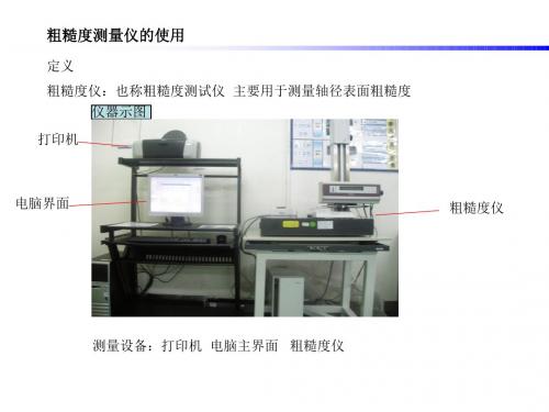
粗糙度测量仪的使用
4 部品测量 4-1 设定测量条件
STEP1
单击电脑上方的测量条件或双击电脑菜单左下方或者双击页 面左下方测量条件处跳出测量条件
粗糙度测量仪的使用
STEP2
设定测量条件数据 基准长度=评价长度÷区间数 评价长度:为图纸指定需要测试范围的长度 区间数:一般为5最小不可以小于2
2 打开软件 电脑主页面上双击surfpak 软件
粗糙度测量仪的使用
3 校正测量 3-1 校正片放于测量平台进行仪器校正
校正片
摇杆控制方向器
校正片放于测定台面上,通过选择X,Y,Z, (红灯显示)来控制摇杆上下左右方向,设 定测定头测量位置
粗糙度测量仪的使用
3-2点击电脑界面测量菜单,下拉检测器校正测量 STEP
粗糙度测量仪的使用
4-2 参数的设定 STEP3
电脑上方单击设置 ,下拉设置参数条件
粗糙度测量仪的使用
STEP4
选择评价条件下的参数方框并选择Ra,Ramax,Rz,Ry栏里打勾确定 单击自动开始运行开始检测
粗糙度测量仪的使用
STEP5
得出的结果即部品表面粗糙度的实测值
粗糙度测量仪的使用
5 关机
粗糙度测量仪的使用
定义 粗糙度仪:也称粗糙度测试仪 主要用于测量轴径表面粗糙度
仪器示图 印机
电脑界面
粗糙度仪
测量设备:打印机 电脑主界面 粗糙度仪
粗糙度测量仪的使用
测量流程 (日常操作) 1 开机 2 打开软件 3 校正测量 4 部品测量 5关机
粗糙度测量仪的使用
Surftest SJ-400 便携式表面粗糙度仪 产品使用手册说明书

Requirement1Requirement2Requirement3Requirement4Revolutionary New Portable Surface Roughness Testers Make Their DebutLong-awaited performance and functionality are here: compact design, skidless and high-accuracy roughness measurements, multi-functionality and ease of operation.SJ-401SJ-402SJ-401Measurement/evaluationof stepped features and straightnessUltra-fine steps, straightness and waviness are easily measured by switching to skidless measurement mode. The ruler function enables simpler surface feature evaluation on the LCD monitor.Roughness parameters that conform to international standardsThe SJ-400 Series can evaluate 36 kinds of roughness parameters conforming to the latest ISO, DIN, and ANSI standards, as well as to JIS standards (1994/1982).Cylinder surface roughness measurements with a hand-held testerThe skidless measurement and R-surface compensation functions make it possible to evaluate cylinder surface roughness.Surftest SJ-400 SeriesHigh-accuracy measurements with a hand-held testerA wide range, high-resolution detector and an ultra-straight drive unit provide class-leading accuracy. DetectorMeasuring range: 800µmResolution: 0.000125µm (on 8µm range) Drive unitStraightness/traverse length SJ-401: 0.3µm/.98"(25mm) SJ-402: 0.5µm/1.96"(50mm)Requirement6Requirement5Advanced data processing with extended analysisThe SJ-400 Series allows data processing identical to that in the high-end class. These data analysis and report creation capabilities are achieved using the surface roughness analysis program FORMTRACEPAK V5 or SJ-Tools.Calculation Result ScreenMeasured Profile ScreenFine contourmeasurement with an auto-leveling tableDeep groove measurementUpside down measurementCylinder measurement with a support footMeasurement ApplicationsR-surface measurementConfirmation of measurement results and assessed profiles without a printoutThe large, integrated, touch-panel LCD monitor clearly displays evaluation results and measured profiles.SkidTraverse directionTraverse directionTraverse directionTraverse directionRuler Analysis ScreenTilt compensation function• The Tilt Compensation Datum Points are selectable from all of the profile (choose P1 and P2) or any arbitrary two sections on the profile (choose P1, P2, P3 and P4), as required. If you choose adjacent sections for tilt compensation then the characteristics of features of interest between these sections, such as scratch depth, etc, can be measured directly.Simplified surface feature evaluationwith the ruler function• This function determines the coordinate difference between two arbitrary points so feature characteristics, such as step height and width, etc, can be measured.Ruler function keyRuler keyCoordinate differenceRulerSkidless measurementSkidded measurementHeight adjustmentDAT screen guides the user when levelingAdjust the micrometer head by -0.928mm to levelTurn tilt adjustment knob by 1.37 turns counter-clockwise to levelWith the SJ-400 mounted on a stand, the DAT function also works with the optional leveling table.Powerful Support for LevelingThe height/tilt adjustment unit comes as standard for leveling the drive unit prior to making skidless measurements and, supported by guidance from the unique DAT function, makes it easy to achieve highly accurate alignment.(skidless measurement)Usually, a spherical or cylindrical surface (R-surface) cannot beevaluated, but, by removing the radius with a filter, R-surface data is processed as if taken from a flat surface.Built-in thermal printerA high quality, high-speed thermal printer prints out measured results. It can also print a BAC curve or an ADC curve as well as calculated results and assessed profiles. These results and profiles are printed out in landscape format, just as they appear on the LCD, in easy-to-understand form.Measurement of a cylindrical surfaceStatistical processing can be performed on multiple measurements for one roughness parameter. Histograms can be displayed and printed in addition to statistical results (mean, standard deviation, maximum/minimum value and acceptance ratio).More Measuring FunctionsThan Expected From a Compact TesterCalculation Result Screen with GO / NG judgment resultUpper and lower tolerance limits can be set for up to 3 roughness parameters. A GO/NG indication is displayed after a measurement. The calculation result is highlighted if NG.Calibration ScreenThe SJ-400 Series is equipped with Ra calibration and stepcalibration methods for detector calibration (gain adjustment). In both calibration methods only the calibrated value of the precision specimen needs to be entered. No other operations are required to calibrate the tester.The measurement conditions and data can be stored in the control unit or memory card (optional) and recalled as required. Batch printout of data after on-site measurement improves measuring efficiency.Key maskingLocks out input from the touch panel keys. This eliminates the possibility of the operator accidentally changing the calibration or measurement conditions.Real samplingThis function samples stylus displacement for a specified timewithout engaging detector traverse. This function has a wide range of uses, such as a simplified vibration meter or a displacement gage incorporated in another system.RecalculatingPreviously measured data can be recalculated for use in other evaluations by changing the current standard, assessed profile and roughness parameters.CustomizingThe SJ-400 Series can be set up to calculate and display only a subset of the roughness parameters available. Parameters can be added later for recalculation, if required.Customized ScreenGO signNG signInvalidatedStorage capacityMeasurement conditionsControl unit: 5 conditions Memory card: 20 conditionsMeasurement dataMemory card: 50 or more pieces of dataArbitrary length measurementThis function allows a sampling length to be arbitrarily set in .004" (0.1mm) increments SJ-401: .004" to .98" (0.1mm to 25mm), SJ-402: .004" to 1.96" (0.1mm to 50mm). It also allows the SJ-400 Series to make both narrow and wide range measurements.Simplified Communication Program (SJ Tools)One of the various functions of the Surftest SJ-400 Series is the ability to use RS-232 with a simplified communication program that allows the transfer of measurement data into a calculation software. The program must be used with Microsoft Excel to generate the inspection report and/or certificate.Required environment:* OS:* Spreadsheet software:Windows 2000-SP4 Microsoft Excel 2000Windows XP Microsoft Excel 2002 Windows Vista Microsoft Excel 2003Windows 7Microsoft Excel 2007Requires RS-232C cable (Optional)SJ-400 Series RS-232C cable Order No. 12AAA882*RS-232C cable D-sub9pin x 2 (store purchase) is a straight cable.*RS-232C a cannot be used in a USB connector.This program can be downloaded for free from the Mitutoyo website.http://www.mitutoyo.co.jpSee the FORMTRACEPAK brochure (Bulletin No. 2010) for more details.*Windows OS & Microsoft Excel are products of Microsoft Corporation.Carrying caseis a standard accessoryFor ultra small holeFor small slotted holeDetail-ABall ø0.5.02”(0.6)ø2.4ø0.3A737.743.87 1.72"(43.8)1.48"(37.7).33"(8.5)ø.02"(ø0.5).17"(4.3)ø.01"(ø0.3)ø.13"(ø3.2)ø.09"(ø2.4).12"(3.1).01(0.06"(1.6)ø.02"(ø0.6)90 (S=5/1)Detail - A .13"(3.4).06"(1.6).02"(0.6)A 12AAC732 [.08"(2m)]*112AAB404 [.18"(5m)]12AAB416 [.39"(10m)][ ]: Tip radius 12AAC733 [.08"(2m)]*1ø.55"(ø14).28"(ø7.2).14"(3.6).2(6.22"(5.6).11"(2.8)ø.12"(ø3)"(1.6).61"(15.6)ø7.2) R .22"(5.6).85"(21.5).14"(3.6).92"(23.5).14"(3.5).27"(6.8).29(7.5Stylus tip position 15012AAB344 12AAB345178-043-1 (mm)178-053-1 (inch/mm)Leveling table (for D.A.T. function)• Can be used with the XY leveling tables.Table swivels: ±1.5° Table size:5.12"x3.94" (130x100mm)Max. Loading: 15kgfMemory cardStores/recalls the measuring conditions (up to 20), measured data, and statistical data.Memory: 8MBMeasuring data output Others Manual column standColumn travel: 7.87"(200mm)Dimensions: 14.57"x7.87"x29.13"(370x200x740mm)Mass: 28.66 lbs. (13kg)264-005DP-1VRPerforms various statistical processingCylinder attachmentUsed to attach on a cylinderDiameter: ø.59" up to 2.36" (ø15mm up to 60mm)SPC connecting cablesConnects a control unit with DP-1VR.3'(1m): 9369376'(2m): 965014Reference step specimenUsed to calibrate detector sensitivity.Step nominal value: 2µm/10µmLCD protective sheetFor touch panel protection (10 sheet set)Five rolls 984'(25m)Standard paper: 270732178-009178-048 (mm)178-058 (inch/mm)178-611 (mm)178-612 (inch/mm)178-019Precision vise• Can be used with the XY leveling table.Input toolData input device for spreadsheet software.264-503A (120V)12AAB358Note: All information regarding our products, and in particular the illustrations, drawings, dimensional and performance data contained in this printed matter as well as other technical data are to be regarded as approximate average values. We therefore reserve the right to make changes to the corresponding designs. The stated standards, similar technical regulations, descriptions and illustrations of the products were valid at the time of printing. In addition, the latest applicable version of our General Trading Conditions will apply. Only quotations submitted by ourselves may be regarded as definitive.Mitutoyo products are subject to US Export Administration Regulations (EAR). Re-export or relocation of our products may require prior approval by an appropriate governing authority.Trademarks and RegistrationsDesignations used by companies to distinguish their products are often claimed as trademarks. In all instances where Mitutoyo America Corporation is aware of a claim, the product names appear in initial capital or all capital letters. The appropriate companies should be contacted for more complete trademark and registration information.© 2011 Mitutoyo America Corporation, Aurora IL 1110-04 Printed in USA, January 2011Specifications are subject to change without notice.。
2020年粗糙度仪操作规范翻译精品版
11 先决条件1.1 目的和指导书目标本操作指导书描述了根据ISO 4287、GB/T 3505-2000标准检测要求,进行产品表面粗糙度检测的操作步骤。
1.2 总则1.2.1 粗糙度仪的环境湿度范围40%〜60%。
1.2.2 粗糙度仪所处测量室温度要求10℃〜40℃范围内进行。
1.2.3 检测时工件应该保证稳妥可靠的固定于检测夹具上,如果松动则肯定影响测量结果1.2.4 每天工作开始前及结束以后,请用无水酒精清洁仪器的工作台面及测针。
1.2.5 零件在测量前必须清洗干净,无毛刺、外观无明显缺陷、无锈蚀情况。
1.2.7 出现以下情况时检测结果视为无效,应重新复检,以重新复检后的结果为最终结果。
A 检测过程中,测针缺失或松动。
B 工件需要检测的位置存在明显的铸造缺陷如气孔、黑斑等。
1.2.8 粗糙度仪每年应至少进行一次校准。
1.3工作指示启动(引发事件)控制计划中的时间节点,涉及粗糙度性能的产品检查,都可以引发本工作指示的启动。
至少应该按产品工程规范描述的频率对相应产品进行粗糙度性能的检测。
2 受本文件影响的行为和机构工厂QEHS3 术语及符号说明3.1术语3.2符号说明4.工作指示 4.1 检测设备图1-1 霍梅尔粗糙度仪大理石工作台打印机图1-2 轴类检测用夹具 图1-3 盘类检测用夹具4.2控件面板及说明1Waveline 20驱动器1、测针保护罩(Stylus protection ) 保护粗糙度测针意外损伤。
2、测针驱动器(Traverse unit ) 驱动粗糙度测针产生直线运动,采集测量数据。
3、测针角度调节旋钮(Tilt angle adjustment ) 此旋钮可以手动调节测针与水平方向的角度位置。
4、驱动器安装螺母(fixing screw ) 通过此两个螺母,可以把驱动器稳定、可靠的安装在Z 轴立柱上。
5、Z 轴锁紧螺母(fixing screw of z axis )当驱动器通过调节螺母调整到适当的高度位置即用此锁紧螺母来锁定驱动器的位置。
JJ1s一4O测距仪说明书
JJ1s一4O测距仪说明书1,press POWER button to turn on 按电源键 POWER 打开2,confirm your mode with the internal display (default is “last used”setting) 确认你的模式与内部显示(默认是“最后的使用“设置)3,Set your desired mode and start measuring 设置你想要的模式,开始测量 Mode setting:模式设置Target priority modes 目标优先模式1、 press and hold MODE button,then press and hold POWER buttonwithin 0.5 second. 按下并保持住模式按钮,然后同时按住电源按钮在 0.5秒之内2、 Continue to press and hold both buttons(more than 2 seconds)untilfirst target priority mode and distant target priority mode are switched. 继续同时按住两个按钮(超过 2 秒),直到第一个目标优先模式和遥远的目标优先模式切换。
3、 if the button is not pressed within 0.5 second ,the displayunit<m/yd./ft.>will be switched. 如果按钮不是压在 0.5 秒之内,显示单元<米/码/英尺。
>将切换。
Dst:Distant priority mode (factory setting)遥远的优先模式(工厂设置)1st:first priority mode 第一优先模式Measurement modes 测量模式Press and release MODE button. 按下和释放模式按钮Measurement mode changes in the order of 1 (Act)to 6 (Hor)as shownbelow. 测量模式变化的顺序 1(Act)到 6(Hor)如下所示。
三丰SURFTEST SJ-400系列便携式表面粗糙度测量仪-产品手册说明书

2Requirement1High-accuracy measurements with a hand-held testerA wide-range, high-resolution detector and an straight drive unit provide superior high-accuracy measurement in its class.<Detector>Measuring range: 800µmResolution: 0.000125µm (at 8µm range)<Drive unit>Straightness/traverse lengthSJ-401: 0.3µm/25mm SJ-402: 0.5µm/50mmRequirement5Advanced data processing with an extended analyzing programThe SJ-400 series allows data processing that is identical to that in the high-end class. These data analysis and report creation capabilities can be achieved with this system using the surface roughness analyzing program SURFPAK-SJ.Requirement3Measurement of cylinder surfaceroughness even with a compact typeThe skidless measurement and R-surface compensation functions make it possible to evaluate cylinder surface roughness.Requirement2Roughness parameters that conform tointernational standardsThe SJ-400 series performs 36 kinds of roughness measurements that conform to the latest ISO, DIN, and ANSI standards as well as to JIS standards (1994/1982).Now, long-awaited specifications and functions are at hand: compactness,skidless measurement, high-accuracy roughness detection, multi-function, and ease of operation.Revolutionary New Portable Surface Roughness Testers Make Their Debut!SJ-401SJ-402SJ-401Requirement4Measurement/evaluation of stepped features and straightnessUltra-fine steps, straightness and waviness can be measured by switching to the skidless measurement function. The ruler functionenables simpler surface feature evaluation on the LCD monitor.3Surftest SJ-400Calculation Result screen Measured Profile screenRequirement6Confirmation of a measurement results and an assessed profile without printoutUsing the integrated large touch-panel LCD monitor,measurement results and an assessed profile can be clearly displayed.Measurement ApplicationsRuler Analysis screenA variety of accessories•A stylus and a nosepiece can be selected according to the measurement condition. (See page 9 – 11.)Simplified surface feature evaluation with the ruler function•This function determines the coordinate difference between two arbitrary points, such as a step height and a pitch interval.The SJ-400 series employs a detector with exchangeable nosepiece that is interchangeable between skidless measurement and skid measurement. It allows optional evaluation according to measurement conditions.NosepieceRuler function keyRuler keyCoordinate differenceRulerStylusDetectorSurftest SJ-400DAT screen showing the amount to be adjustedThe D.A.T. FunctionThe height-tilt adjustment unit comes as standard for powerful support of the leveling operation at skidless measurement. This unique and convenient function has achieved high-accuracy measurement with ease of operation.Move the micrometer head by this amount.Digimaticmicrometer headLeveling table (for D.A.T.)When using with the stand,the D.A.T. function can work with the optional leveling table.Support for R-surface roughness measurement (skidless measurement)Usually a workpiece with a spherical or cylindrical surfacecannot be evaluated. By eliminating the round surface element with a filter, this function processes this R-surface data as if it was taken from a flat surface.Built-in thermal printerA high-quality, high-speed thermal printer prints out measured results. It can also print a BAC curve or an ADC curve as well as calculated result and assessed profile. These results and profiles can be printed out in landscape format, just as they appear on the LCD. They are presented in an easy-to-understand form.Measurement of a cylindricalsurfaceStatistical processing functionThis function performs statistical processing of multiplemeasurements for one roughness parameter. It is possible to display and print histograms in addition to statistical results (mean, standard deviation, maximum value/minimum value,and acceptance ratio).StatisticalHistogramsSwitchableSurftest SJ-400Calculation Result screen with GO / NG judgment resultAccording to the upper/lower tolerance limits set the GO/NG judgment sign is displayed and the calculation result is highlighted (max. for 3 roughness parameters).Calibration screenThe SJ-400 series is equipped with the Ra calibration and step calibration methods for detector calibration (gain adjustment).In both calibration methods only the reference value described in the precision specimen needs to be entered. No other operation such as volume control is required.and conditionsIt is possible to save the measurement conditions and measured data in the control unit or memory card (optional) and to recall the data from both.Batch printout of the measured data after performing on-site measurement and saving the data will raise measurement efficiency.This function invalidates the key operation on the touch panel.Since only the sheet key operation is valid, there is no chance for error in data, including calibration conditions and measurement conditions.This function samples a displacement of the stylus for the specified time without traversing the detector.It has a wide range of uses such as a simplified vibration meter or a displacement gage incorporated in another system.It is possible to recalculate already measured data for other evaluation by changing the current standard, assessed profile and roughness parameters.This function allows a sampling length to be arbitrarily set in 0.1mm increments (SJ-401: 0.1mm to 25mm, SJ-402: 0.1mm to 50mm). It also allows the SJ-400 series to make both narrow and wide range measurements.Customize functionThis function selects only the necessary parameters forcalculation/display from a variety of roughness parameters. It is also possible to add parameters later for recalculation.Customized screenGO signNG signInvalidatedSURFPAK-SJ SpecificationsEvaluation Curve displayAnalysis graph displayEvaluation condition displayMeasurement condition displayCalculation result display Analysis screenSurftest SJ-400Carrying case is a standard accessory10Detector178-396-2: 0.75mN measuring force, with 12AAC731 standard type stylus (2µm tip radius)178-397: 4mN measuring force, with 12AAB403 standard type stylus (5µm tip radius)Set configuration/Dimensionsø146.83.6146027.2ø8ø142410.42.8DetectorSkid nosepiece (12AAB344)Stylus ø14ø7103.13.61.3Skidless nosepiece (12AAB355)90°0.937.77.644.7ø2.4ø1.25.2A Distinguish colorDetail - A0.60.41.6ø0.690°(S=5/1)Detail - A ø2.415ø1.23.42.41.60.637.744.4ADistinguish color0.41.2ø0.390°(S=5/1)Detail - A ø2.48.9ø0.62.537.71.244.2ADistinguish colorø0.390°Distinguish color0.80.4Detail - A (S=5/1)ø2.437.72.5ø0.68.944.20.8Aø2.487.70.9Ø1.290°94.77.65.2A distinguish color Detail - Aø2.4137.70.97.6144.7ø1.290°5.2ADistinguish colorDetail - Aø14Ø7.2R 403.623.53.56.73.65.621.5 2.8Stylus tip positionø14ø3R 400.61.63.621.5 5.63.623.51.43.515.6ø7.23.8R2Stylus tip positionø14R 403.61.222.321.5ø1.926.73.53.8ø7.2Stylus tip positionø7ø141.33.6421.5103.5Stylus tip positionø14R 405.621.5 3.623.53.53.6ø7.26.87.5Stylus tip position150°Standard type12AAC731 (2µm)*112AAB403 (5µm)12AAB415 (10µm)( ): Tip radiusSmall hole type12AAC732 (2µm)*112AAB404 (5µm)12AAB416 (10µm)( ): Tip radiusExtra small hole type12AAC733 (2µm)*112AAB405 (5µm)12AAB417 (10µm)( ): Tip radiusExtra small hole typeDeep hole type12AAC734 (2µm)*112AAB406 (5µm)12AAB418 (10µm)( ): Tip radius2 x stylus12AAC740 (2µm)12AAB413 (5µm)12AAB425 (10µm)( ): Tip radius3 x stylus12AAC741 (2µm)*112AAB414 (5µm)12AAB426 (10µm)( ): Tip radius12AAB35512AAB34412AAB34512AAB34612AAB347Skidless nosepieceUnit: mmStylusApplicable skid nosepiece*1 Tip angle is 60°11Surftest SJ-400Deep groove type*212AAC735 (2µm)*112AAB409 (5µm)12AAB421 (10µm)( ): Tip radiusExtra deep groove type*212AAC736 (2µm)*112AAB408 (5µm)12AAB420 (10µm)( ): Tip radiusExtra deep groove type*212AAC737 (2µm)*112AAB407 (5µm)12AAB419 (10µm)( ): Tip radiusGear face typeEccentric type*2*1 Tip angle is 60° *2 At using this stylus, measuring force of the detector does not guarantee.12AAB339 (2µm)*112AAB410 (5µm)12AAB422 (10µm)( ): Tip radius12AAC739 (2µm)*112AAB412 (5µm)12AAB424 (10µm)( ): Tip radiusKnife edge type12AAC738 (2µm)*112AAB411 (5µm)12AAB423 (10µm)( ): Tip radiusWE-curve type12AAB33812AAB349StylusApplicable skid nosepiece12AAB35012AAB35112AAB35212AAB34812AAB35312AAB35413ø2.40.9ø1.290°14.237.744.7ADistinguish ColorDetail - A230.9ø2.424.2ø1.290°37.744.7A Detail - ADistinguish color3533.85.2ø1.2A Distinguish colorø2.4Ø2.490°37.745.2Detail - A60°60°7.66.437.743.8ø1.2ø2.4ADistinguish colorDetail - A7.6ø2.4ø1.20.937.744.7Ball ø1.5885.27.6ø2.4ø1.290°37.70.944.7ADistinguish colorDetail - AADetail - A37.70.990°ø0.6Distinguish color457.610ø2.4ø2.4ø14R 4012.80.61.41.43.53.819.5 1.821.54.53.6109ø7.2Stylus tip positionR24.4ø14ø7.2R 403.623.51.413.421.5 5.63.6 2.8103.5Stylus tip positionR2ø14ø7.2(8.4)3.63.819.51.821.53.513.4 2.55910Stylus tip positionø1.5ø14R 4017.9Ø7.23.521.553313.64.513.49 1.4511.610R210Stylus tip positionø14R 403.53.819.5 1.821.522.80.61.42720Ø7.29Stylus tip positionR21.44.4ø14R 401.43.50.521.5ø7.219.72.36.14.50.61.43.62.3R2Stylus tip position4.4ø14R 4021.56.7ø7.25.63.63.63.523.52.8Stylus tip positionFlat Unit: mm12Order No.178-019Mounting method Two-sliding- jaw Clamp opening 36mm/1.42”Clamp width 44mm/1.73”Clamp depth 16mm/.63”Height38mm/1.50”Stand, TablesManual column standColumn travel: 200mmDimensions: 370x200x740mm Mass: 13kg178-009178-042-1 (mm)178-052-1 (inch/mm)178-049 (mm)178-059 (inch/mm)XY leveling tables178-019Precision vise•Can be used with the XY leveling table.74313178-043-1 (mm)178-053-1 (inch/mm)Order No.178-042-1,178-052-1178-043-1,178-053-1178-049,178-059Table size130 x 100mm/5.12” x 3.94”Maximum loading weight 15KgInclination angle±1.5˚—Horizontal rotating angle ±3˚—X, Y axis displacement ±12.5mm/.49”±12.5mm/.49”±12.5mm/.49”Min. reading0.001mm/.00005”*0.001mm/.001”*0.001mm/.00005”*of the micrometer head Dimension 262 x 233 x 83mm220 x 189 x 83mm262 x 233 x 55mmMass6.3kg6kg5kg* Digital display13Surftest SJ-400Leveling table•Can be used with the XY leveling table.Table swivels: ±1.5°Table size: 130x100mm Max. Loading weight: 15kgMemory cardSaves/Retrieves the measuring conditions (up to 20), measured data, and statistical data.Memory: 8MBOthers 264-005DP-1VRPerforms various statistical processingCylinder attachmentUsed to attach on a cylinderDiameter: ø15mm up to 60mmSPC connecting cablesConnects a control unit with DP-1VR.1m: 9369372m: 965014Reference step specimenUsed to calibrate detector sensitivity.Step nominal value: 2µm/10µmLCD protective sheetFor touch panel protection (10 sheets set)Printer paperFive rolls (25m)Standard paper:270732Durable paper:12AAA879178-048 (mm)178-058 (inch/mm)178-611 (mm)178-612 (inch/mm)2 (.08")99 (3.90")79 (3.11")57.5(2.26")Ø50 (1.97")Input toolData input device for spread sheet software.264-503 (100V)264-503A (120V)264-503D (220V)264-503E (240/220V)12AAA84112AAA89612AAB358MichiganPhone: (734) 459-2810IllinoisPhone: (630) 978-5385CaliforniaPhone: (626) 961-9661MassachusettsPhone: (978) 692-8765IndianaPhone: (317) 577-6070North CarolinaPhone: (704) 875-8332Coordinate Measuring Machines Small Tool Instruments and Data ManagementHardness Measuring Sensor Systems Optical Measuring Digital Scale and DRO Systems Surface-, Form- and Contour MeasurementVision Measuring Systems Note: All information regarding our products, and in particular the illustrations, drawings, dimensional and performance data contained in this pamphlet, as well as other technical data are to be regarded as approximate average values. We therefore reserve the right to make changes to the corresponding designs, dimensions and weights. The stated standards, similar technical regulations, descriptions and illustrations of the products were valid at the time of printing. In addition, the latest applicable version of our General Trading Conditionswill apply. Only quotations submitted by ourselves may be regarded as definitive.Job No.11B-826.800308 (1) C N E , P r i n t e d i n J a p a n。
三丰通用测量程序操作指南
本手册中所使用的标记
各种注释
通过正确的操作帮助我们获取高可靠性测量数据的各种“注释”,用下列各种术语进行区分 表示。
要点 • 对实现目标所必需的信息进行的注释。不可无视该项指示。
• 提示如不遵守该指示,则有可能损害主机的性能、精度亦或有可能给维护机器运转带来困 难。
注释 提示本文中特别重要的、需要强调、补充的信息。指出进行特定操作时的特别注意事项(存
储限制、设备结构、有关程序特定版本的信息等)
参考
提示本文所记载的操作方法、顺序应用于特殊问题时的参考信息、操作及相关功能的详细 说明。
另外,还有其他参考信息时则提示信息之所在。
对由于不遵守本说明书所述使用方法而造成的损害,本公司概不负责。 本公司可能对说明书中所记事项不做予告进行更改。
三丰量具说明书

三丰量具产品保养
• 三丰量具使用时 • (1)测量时与工件接触应适当,不可偏斜,要避免用手触及测量面, 保护三丰量具。 • (2)测量力应适当,过大的测量压力会产生测量误差,容易对三 丰量具有损伤。 • (3)工件之夹持方式要适当,以免测量不准确。 • (4)不可测量转动中的工件,以免发生危险。 • (5)不要将三丰量具强行推入工件中或夹虎钳上使用。 • (6)不可任意敲击、乱丢或乱放三丰量具。 • (7)特殊量具的使用,应遵照一定的方法和步骤来使用。
三丰数显卡尺测量方法:可以直接利用数据采集仪连接数显卡尺实现高效测量零 件的长度、内外径和深度等。
三丰卡尺篇
• 专用卡尺
• 另外,还有各种非标专用的卡尺,如测量沟槽深度的带钩深度卡 尺、测量 • 齿轮厚度的齿厚卡尺、测量物体高度的高度卡尺和测量焊接质量 的焊缝卡尺(焊缝规)等。
三丰卡尺篇
• •
•
三丰卡尺篇
• 数显卡尺
• 数显卡尺是采用容栅、磁栅等测量系统,以数字显示测量示值的 长度测量工具。常用的分辨率为0.01mm,也有分辨率为 0.005mm的高精度数显卡尺。相比游标卡尺及带卡尺,数显卡 尺读数更直观、清晰,测量效率较高。
三丰卡尺篇
• • • • • • • • • • •
•
数显使用方法 三丰数显卡尺的使用方法: 一、准备工作 1)擦干三丰数显卡尺尺身表面,清洁各测量面 2)松开紧固螺钉,移动尺框,检查显示屏和各按键工作是否正常 二、开始测量 1)按开关键打开电源 2)按公英制转换键选择所需单位制 3)移动尺框,使两外测量面手感接触后按置零键置零,即可进行正常测量。 三、读数方法 直接在LCD显示窗读取所测值。
三丰卡尺篇
• 三丰卡尺是卡尺中在国内使用比较广泛的卡尺 之一,源自于日本株式会社三丰。是一种测量 长度、内外径、深度的三丰量具。
- 1、下载文档前请自行甄别文档内容的完整性,平台不提供额外的编辑、内容补充、找答案等附加服务。
- 2、"仅部分预览"的文档,不可在线预览部分如存在完整性等问题,可反馈申请退款(可完整预览的文档不适用该条件!)。
- 3、如文档侵犯您的权益,请联系客服反馈,我们会尽快为您处理(人工客服工作时间:9:00-18:30)。
SJ-401粗糙度测试仪操作说明测量操作规程(仅供参考)总的测量流程:如下流程概述了SJ-400的基本操作要求设定SJ-400→3.3连接和拆卸驱动装置和探测部分.→3.3.3检查零点→3.3.4调节连接器高度→3.4升高和降低高度-倾斜调整装置.电源→3.7打开或关上电源修改测量条件→第五章修改测量条件向上/向下放置或水平放置→4.2 调整校准和测量实施校准→4.3校准进行工件测量→4.4测量输出测量结果→4.6打印测量结果→第11章维护和检测SJ-400■ 根据要求修改测量条件下表列出SJ-400可修改的测量条件,出厂前SJ-400已经被设定成表中的默认值。
测量条件默认值备注引用表面粗糙度标JIS2001设定理想中的一种 5.1准被测轮廓R-PROFILE 5.20.8mm 5.2截断长度(取样长度)滤波器GAUSS 5.2随意评价长度-适用于带校准长度的测量 5.4取样长度的数X5量粗糙度参数Ra,Rz,Rq可以指定显示的参数合格/不合格的判定如果要求进行合格/不合格的判定,根据工件设定上限和下限倾斜补偿设定是否补偿被测工件轮廓的整个或任意片段.R面补偿测量速度返回速度自动返回预行程/已测行程测量范围触针驱动单元操作Ra校准值阶段校准值连接速度bps根据已连接的计算机必须设定9600,19200或28800bps任一数值奇偶数停止位打印项目测量条件,测量结果,评价曲线.打印方法打印格式水平放大自动可以选择水平放大打印评价曲线.垂直放大自动可以选择垂直放大打印评价曲线.自动睡眠4.2 调整校准和测量如果在建立样本或工件的校准或测量前SJ-400已经安装了,必须实行“向上/向下测量(调整驱动/探测单元的高度)以及”水平测量(调整驱动/探测单元的斜度)。
4.2.1 向上/向下测量实行向上/向下测量时,使用高度/倾斜调整单位和简单的立柱(可选).■ 用高度/倾斜调整单位进行向上/向下测量通过旋转在高度//倾斜调整单位上的向上/向下旋钮,调节驱动/探测装置的高度以便触头适当地接触样品或工件测量表面。
触针适当接触后检查主屏幕上电平指示仪。
■ 用简单的立柱进行向上/向下测量使用简单的立柱可以调节驱动/探测装置向上/向下测量。
4.2.2 零点校准■ 校零程序第二个主屏幕或DAT measure屏幕二者中任一个都可以实行校零。
假设当前触针指向零点,实行二个校零程序中的任一个都允许SJ-400实行测量和计算。
不过,校零的实行范围限制触针物理位置在±100um范围内。
如果触针物理位置超出±100um范围实行校零,其结果是错的。
在这种情况下,要重新进行校零以使偏离物理位置的触针回到±100um范围内。
4.2.3 水平测量针对水平测量驱动/探测装置,DAT功能调整程序和目视调整程序均是有效的。
DAT功能是一个“水平测量支持功能”。
使用这个功能可以精确地水平测量驱动/探测装置。
如果不需要精确水平测量,可以使用目视调整程序。
■ DAT功能水平测量运行,视觉上做到精细调节可能有困难如驱动/探测装置极um向上/向下的移动。
因此,SJ-400配置DAT功能,它将显示带数字触摸屏上向上/向下移动。
在SJ-400屏幕上显示向上/向下移动情况,如高度-倾斜调整装置倾斜按钮的转动数字或水平工作台的调整数据.Tip提示:使用水平工作台时,简易的柱体是必须的。
关于如何使用柱体的资料,请参考10.1节“简易柱体”。
■ 带DAT功能的倾斜调整在触摸屏的主页上使用DAT功能实行DAT测量,以及根据测量结果调节高度-倾斜调整装置或水平工作台,方法如下:1.在主页上触摸“DAT”按钮,显示DAT测量屏幕。
2.如果高度-倾斜调整装置是用水平测量,打开屏幕通过触摸“倾斜调整数量装置“按钮显示倾斜旋钮的转动数量。
如果使用水平工作台测量,进入程序3。
3.如果使用水平工作台,通过按“ZERO/ABS“按钮进行零位设定计量显示器数值,如果使用高度-倾斜调整单元,进入程序4。
4.在显示装置上按“START/STOP”键。
实行DAT测量。
水平测量调整数量在屏幕上显示出来。
5.为了防止探测器或触针的损坏,在调整倾斜前,将触针从工件上移开。
高度-倾斜装置:通过顺时针转动倾斜按钮来升高驱动/探器装置。
水平工作台:通过顺时针转动立柱手柄升高驱动/探器装置。
6.根据屏幕上各个的高度-倾斜装置转动的数量或水平工作台调整数量,通过转动倾斜按钮或测微头来调整水平。
Important:数显头转动方向取决于驱动/探测装置和数显头的位置关系,如上表中的图形已经写明了转正方向。
转动方向相反,位置关系也是相反的。
7.调整完成后,在工件上设置探针合适的位置,然后通过上-下移动把探针放到靠近工件中心的位置。
8.通过按“START/STO”键,再一次确认完成了用DAT测量方式的水平测量。
Tip:如果要求更精确的水平测量,请重复步骤3—8。
如果触摸了DAT测量屏幕上的“ZERO ADJ”按钮,那时的触针位置变成测量的零点。
进一步信息,请参见4.2.2节“零位校准”Important:在水平测量情况下,为了避免探测器的损坏应保持触头远离工件。
如果实行水平测量而探针接触工件,将出现如下情况。
当高度-倾斜调整装置降低时(顺时针转动高度-倾斜调整装置的倾斜按钮,顺时针转动水平工作台上数显头),那时仪器可能会发出嘟嘟的响声,中断水平测量方式以避免探测器损坏。
然后校正工件重启。
如果没有实行校正,在过多的压力下探测器将会受损。
■ 目视调整(调整在用的电平指示仪)触摸屏主页上的电平指示仪显示当前探针位置。
与此同时留意这个电平指示仪调整高度-倾斜调整装置(驱动/探测装置的倾斜)或水平工作台(工件的倾斜)如果说电平指示仪指在中间,探针接近处于零位。
● 使用高度-倾斜调整装置水平测量(针对无轨测量)1.调到第三主页面。
2.检查是否主页的电平指示仪指向中间。
NOTE:必须确保详细研究驱动/探测装置因为这是水平测量的基本操作。
3.在第三页面按下“MOVE ORIGIN”或“Move Meas.StartPosition”切换到探测器。
4.实行第三步后,检查是否电平指示仪指向位置(驱动范围终点)有别于第二步检查位置(驱动范围的起点)5.如果电平指示仪显示不同,进入第六步进行水平测量。
如果电平指示仪相同,不需要进行水平测量(因为已经是水平的)。
6.转动倾斜按钮,观察电平指示仪指向以便它能显示在中间。
操作前后电平指示转动倾斜按钮的说明(从顶端起)仪-side逆时针:相比较调整前的状况,图中驱动/探测器装置的左边升高+side顺时针:相比较调整前的状况,图中驱动/探测器装置的左边降低。
7.再次调整向上/向下测量因为调整后可能切换电平指示仪已标明位置。
Tip:关于向上/向下测量的资料请参见4。
2。
18.按“Move Origin”或“Move Meas。
Start Position”图标切换到探测器,然后检查水平测量已经接近完成了。
Tip:如果触摸第二个主面上的“Zero Adj.”,这时的触针变成测量时的零位。
进一步零位调整信息请参见4.2.2.Important:如果顺时针转动倾斜旋钮,当心触针和驱动/探测器装置变成如下情形。
如果变成如下情况,停止通过转动倾斜旋钮来进行水平测量,针对工件重新设定,从设定驱动/探测器装置到合适位置。
● 用高度-倾斜调整装置的水平测量(针对有轨测量)有轨测量的水平测量要求不精确。
不过,实行在测量范围内的目视水平测量及不会发生超出范围的水平测量。
● 用水平工作台的水平测量如果使用水平工作台(可选),通过倾斜工件可以使工件和驱动/探测器装置在同一水平。
水平测量程序基本和高度-倾斜调整装置一样,除了转动水平工作台的数显测头来代替转动倾斜旋钮。
操作前后电平指示转动数显测头的说明(从右边起)仪-side顺时针:相比较调整前的状况,图中水平工作台表面的右边是升高。
+side逆时针:相比较调整前的状况,图中水平工作台表面的右边是降低。
4.3 校准SJ-400带简单的程序可以进行校准。
校准分为二种方法:一种是使用标准的精密、粗糙度样本的Ra校准,另一种是使用可选的阶差规或阶差校准块的阶差校准。
表面粗糙度测量仪的Ra校准是通过测量精确的粗糙度标准块(也称校准测量)而实行的,如果出现测量值和标准值二者中任何一个不相同,那么调整差异(得到校准)。
阶差校准是采用测量阶差规(阶差规或阶差校准块),如果出现测量值和参考值(粗糙度标准块)二者数值有差异,调整差异。
根据SJ-400使用环境条件和频率,这些校准应定期地实行。
如果仪器第一次被使用或探测器升高了或替换了,校准是必不可少的。
在没有合适地校准仪器情况下,无法获得正确的数据。
4.3.1 标准块设定尽管已经提供了精确的粗糙度校准标准块,可选的阶差规和阶差校准块也是有效的。
使用精确的粗糙度标准块进行Ra校准。
使用阶差规或阶差校准块进行阶差校准。
Note:如果SJ-400需要实行一种除了已有的精确的粗糙度标准块或可选的阶差规(或阶差校准块)外的标准,这种标准只在默认校准条件改变后才可以实行,因为改变后的标准也将适用于粗糙度或阶差标准块。
关于修改校准条件的程序的更多资料,请参见5.17节.■设定SJ-400校准1. 在水平工作台上放合适的标准块.图略: For Ra calibration—Ra校准Level table --- 水平工作台Precision roughness specimen 精确的粗糙度标准块。
For step calibration-(略)Tip:● 带阶差规的2um或79um和10um或394um阶差是有效的。
如果用阶差规实行校准,这个阶差规有一个台阶,接近被测的工件的台阶,这样将获取更多有效的校准测量结果。
● 如果用10um或394um阶差规实行校准,在校准前必须修改校准值。
进一步信息,请参见5.17.2.● 如果阶差规用于校准,如图所示的一个台阶必须安装在驱动/探测器装置和阶差规表面之间。
(驱动/探测器装置设定成水平的,设定探针以便使电平指示计指在零位)。
高度-倾斜调整装置: height-tilt adjustment unit.驱动/探测器装置: Drive/ Detector unit阶差规: Step gage.用阶差块提供一个约为13-23mm的台阶.provide a step ofapproximately 13 to 23mm using gauge blocks.2、在平台上设定驱动/探测器装置,然后,进行向上/向下移动测量和水平测量来调整驱动/探测器装置的高度和倾斜角度。
Tip:如果使用阶差规确定在驱动/探测器装置和阶差规之间的位置关系为的是探针处于除阶差规已标识的测量区域的探针起始线外。