Honeywell显示器产品介绍
霍尼韦尔产品全部资料

霍尼韦尔产品全部资料目录技术部分 (1)一、霍尼韦尔安防(Honeywell Security)简介 (1)1、霍尼韦尔公司简介 (1)2、霍尼韦尔安防(Honeywell Security)发展历程 (2)3、典型项目案例 (3)二、门禁控制系统设计 (7)1、门禁系统构成 (7)2、门禁控制管理软件(Winpak Pro) (10)3、门禁设备参数 (14)1.1 门禁控制功能? 控制所有出入通道控制点的电锁开/关,实行授权安全管理,并实时地将每道门的状态向控制中心报告。
? 通过管理电脑预先编程设置,系统能对持卡人的通行卡进行有效性授权(进/出等级设置),设置卡的有效使用时间和范围(允许进入的区域),便于内部统一管理。
? 系统自动识别进出人员身份,防止外来人员的闯入。
? 全部采用非接触读卡识别方式,系统使用者持有效卡才可以在授权的范围内进出。
? 在重要通道口设置成出入双向监控管理(进/出均需刷卡)。
防反传功能可增强出入通道控制系统的安全性。
? 系统可探测到异常开门情况,具有报警功能。
如有人非法(破坏)将门打开,或是“套用”低级别卡试图潜入重要地点,门禁控制器立即将警情传送给控制中心电脑并提示发案地点,同时记录在案。
1.2 编程管理功能? 有编程权限的管理人员可通过监控终端和管理主机对所发感应卡设定限、取消和重置使用,并可设置门锁的方式。
? 在发生意外时,可由中央控制室控制部分或全部门锁的开闭。
1.3 卡片及持卡人管理功能? 总控中心统一发卡,可将卡制作成工作证、出入证、贵宾卡、临时卡等,并可对不同的卡进行不同的授权。
如工作证可长期使用,临时卡在使用几次或几天后自动失效。
若卡丢失,可在数据库中将其删除;使用过的卡还可重新授权给其他人使用。
? 可以设定卡的生效和截止日期。
? 具有批添加和批删除卡,以及卡查询功能。
? 总控中心发行授权后的IC卡,作为电子钥匙,在卡接近读卡器前,读卡器内指示灯由红变绿,门锁便自动打开。
霍尼韦尔 RT10A 加密平板电脑商品说明书

RT10A加固型平板电脑RT10A加固型平板电脑部署快,低总拥有成本(TCO)低、设备管理方便。
无论您是主管、车间员工、经理还是维护人员,RT10A都能满足您日常工作流的需求。
保持员工和经理互联,随时满足其数据和功能需求对任何企业都无比重要。
为此,您需要既适应工作流程又适合工作人员的移动设备。
若设备不到位,则互联性、数据采集和生产率所带来的好处无从谈起。
霍尼韦尔RT10A加固型平板电脑轻巧耐用,配备10.1英寸高清光学级贴合显示屏,能长时间无疲劳使用,部署快,非常适合企业应用。
在数据采集方面,FlexRange双镜头影像式扫描引擎的读取范围为0.1米(5英寸)(甚至更近)到10.7米(35英尺),用户无需反复进退即可轻松扫描条码,极大地节省了时间。
除灵活性和易用性外,移动设备还必须足够坚固耐用、在生产率方面充分优化,才能最大限度降低总拥有成本。
RT10经久耐用,具有卓越的抗跌落性能和IP65防护等级。
其电池组支持热插拔,可有效缩短设备断电导致的停机时间。
此外,RT10A基于霍尼韦尔Mobility E dge™平台,能向后兼容至Android™ R甚至更高版本,保护您的投资不会过时,保障您的投资永不过时,同时还能快速部署,尽快实现价值。
特点&优势强大的条码扫描功能,包括可即时自动对焦的近距离、中距离和远距离扫描。
借助R T10A和霍尼韦尔O p e r a t i o n a lIntelligence软件能将数据转化可行性行动建议,进而查找并修复设备滥用、无法整夜充电等问题。
结合RT10A和Smar tTa l k,现场员工可保持互联,沟通无碍。
还可通过安全的一键通(PTT)、文字、语音和视频等通信功能连线主题专家。
符合MIL-STD810G标准,具有卓越的抗振动性能(能从1.2米高多次坠落至混凝土地面)和高达IP65的防护等级。
RT10A具有一整套适应多种工作流程的配件,包括用于叉车的车用底座、用于办公室的桌面底座和方便全天携带的手带或肩带RT10A完美结合了坚固耐用和轻巧的结构,明亮的高清屏幕、以及集成式条码扫描功能,不仅能降低总拥有成本,还能提高员工作业效率。
品牌:Honeywell 产品名:HMR3000 型号:HHMR3000 品牌型号说明书

Digital Compass Solution HMR3000The Honeywell HMR3000 is a digital compass module that provides heading, pitch, and roll outputs for navigation. Three Honeywell’s magneto -resistive sensors are oriented in orthogonal directions to measure the vector components of earth’s magnetic field. A fluid tilt sensor is employed to determine a gravitational reference. These solid-state sensors create a strapdown compass that is both rugged and reliable. The data output is serial full-duplex RS-232 or half-duplex RS-485 with 1200 to 19,200 data rates.Applications include: Compassing & Navigation, Dead Reckoning Backup to GPS Systems, Marine Navigation, Antenna Positioning, and Land SurveyingA RS-232 development kit version is available that includes a windows compatible demo program (does not work with RS-485 devices), interface cable, AC adapter and carrying case.Honeywell continues to maintain product excellence and performance by introducing innovative solid-state magnetic sensor solutions. These are highly reliable, top performance products that are delivered when promised. Honeywell’s magnetic sensor solutions provide real solutions you can count on.FEATURES & BENEFITS BLOCK DIAGRAMHigh Accuracy, <0.5° with 0.1° ResolutionWide Tilt Range of ±40° Up to 20 Updates per Second NMEA Standard Sentence Outputs Hard Iron Calibration RoutineRS-232 or RS-485 Serial Data Interfaces PCB or Aluminum Enclosure Options6-15 volt DC Unregulated Power SupplyInterfaceHMR3000SPECIFICATIONSPower SupplyTemperature(2) Tested at 25°C except stated otherwise.(3) Characterized(4) Parts stationary for 24 hours before testing(5) The HMR3000 Demo Kit is not available with the RS-485 interface because the software does not support half-duplex protocol2 HMR3000 3PIN CONFIGURATION(1) Power input shall only be applied to either Pin 8 (+5VDC) or Pin 9 (Unregulated +6 to+15VDC).(2) Exceeding the voltage specifications for Pin 8 may damage the HMR3000.RS-232 UNBALANCED I/O INTERCONNECTSRS-485 BALANCED I/O INTERCONNECTSHMR3000HOST PCHOST PCHMR3000HMR3000DATA COMMUNICATIONSThe HMR3000 serial communications are governed by a simple asynchronous, ASCII protocol modeled after the NMEA0183 standard. Either an RS-232 or an RS-485 electrical interface can be ordered. ASCII characters are transmitted and received using 1 start bit, 8 data bits (LSB first), no parity (MSB always 0), and 1 stop bit; 10 bits total per character. Thebaud rate defaults to 19,200 and can be reconfigured to 1200, 2400, 4800, 9600, 19200, 38400 bits per second. TheHMR3000 supports both standard NMEA 0183 and proprietary messages. Unsolicited NMEA messages are sent by theHMR3000 in Continuous Mode at the rates programmed in the EEPROM. HMR3000 also responds to all input messagesfrom the host. An HMR3000 response to a command input may be delayed due to transmission of an unsolicited output.The host computer must wait for HMR3000 to respond to the last command input before sending another command message. All communication from and to HMR3000 contain a two-character Checksum Field at the end of the data fields,and are denoted in the sentences by ‘hh’. The checksum assures the accuracy of the message transmitted. This checksumis also calculated per NMEA 0183 Standard.The RS-232 signals are single-ended undirectional levels that are sent received simultaneously (full duplex). One signal isfrom the host personal computer (PC) transmit (TD) to the HMR3000 receive (RD) data line, and the other is from theHMR3000 TD to the PC RD data line. When a logic one is sent, either the TD or RD line will drive to about +6 Volts referenced to ground. For a logic zero, the TD or RD line will drive to about –6 Volts below ground. Since the signals are transmitted and dependent on an absolute voltage level, this limits the distance of transmission due to line noise and signalto about 60 feet.When using RS-485(1), the signals are balanced differential transmissions sharing the same lines (half-duplex). This meansthat logic one the transmitting end will drive the B line at least 1.5 Volts higher than the A line. For a logic zero, the transmitting end will drive the B line at least 1.5 Volts lower than the A line. Since the signals are transmitted as difference voltage level, these signals can withstand high noise environments or over very long distances where line loss may be a problem; up to 4000 feet. Note that long RS-485 lines should be terminated at both ends with 120-ohm resistors.Specific measurement descriptions and interface commands are not included in this datasheet but are included in the companion HMR3000 User’s Guide document.(1) Demonstration software for the HMR3000 does not support the RS-485(half-duplex) protocol. The software is onlyavailable with the RS-232 interface.CIRCUIT DESCRIPTIONThe HMR3000 Digital Compass Module contains all the basic sensors and electronics to provide digital indication of headingand tilt. The HMR3000 has all three axis of magnetic sensors on the far end of the printed circuit board, away from the connector interface. The HMR3000 uses the circuit board mounting holes or the enclosure surfaces as the reference mechanical directions. The complete HMR3000 PCB assembly consists of a mother board and the 9-pin D-connector.The HMR3000 circuit starts with the Honeywell HMC1001 1-Axis Magnetic Sensor and the HMC1002 2-Axis Magnetic Sensor elements to provide the X, Y, and Z axis magnetic sensing of the earth’s field. These sensor output voltages arethen amplfied and converted to a digital representation. A microcontroller integrated circuit receives the digitized magneticfield values (readings) by periodically querying the Analog to Digital Converter (ADC) and performs the necessary offsetvalue corrections provided by the EEPROM via the calibration routine. This microcontroller also performs the external serialdata interface and other housekeeping functions. The onboard EEPROM integrated circuit also is employed to retain necessary setup variables for best performance.A liquid filled two-axis (pitch, roll) tilt sensor is also used to create tilt compensated heading data. This tilt sensor performsan electronic gimballing function and is normally mounted flat (PCB horizontal) for maximum tilt range.4 HMR3000APPLICATIONS PRECAUTIONSSeveral precautions should be observed when using magnetic compasses in general:∙The presence of ferrous materials, such as nickel, iron, steel, and cobalt near the magnetometer will create disturbances in the earth’s magnetic field that will distort the X, Y, and Z field measurements.∙Perming effects on the HMR3000 circuit board need to be taken into account. If the HMR3000 is exposed to fields greater than 10 gauss, then it is recommended that the enclosure/circuit boards be degaussed for highestsensitivity and resolution. A possible result of perming is a high zero-field output indication that exceedsspecification limits. Degaussing wands are readily available from local electronics tool suppliers and areinexpensive. Severe field offset values could result if not degaussed.NON-FERROUS MATERIALSMaterials that do not affect surrounding magnetic fields are: copper, brass, gold, aluminum, some stainless steels, silver,tin, silicon, and most non-metals.HANDLING PRECAUTIONSThe HMR3000 Digital Compass Module measures fields within 1 gauss in magnitude. Computer floppy disks (diskettes)store data with field strengths of approximately 10 gauss. This means that the HMR3000 is many times more sensitive than common floppy disks. Please treat the compass with at least the same caution as your diskettes by avoiding motors, CRTvideo monitors, and magnets. Even though the loss of performance is recoverable, these magnetic sources will interferewith measurements.The fluidic tilt sensor works best when kept near level, and in calm to moderate vibration conditions. If turned upside downor violently jarred, not all the fluid will immediately return to the bottom of the tilt sensor’s glass ampoule. Accurate til t andtilt compensated headings may be unavailable for a minute or two to allow for the fluid to transit to the bottom of the ampoule.PCB DIMENSIONS AND PINOUT 5HMR30006 CASE DIMENSIONSDEMONSTRATION PCB MODULE KITThe HMR3000 Demonstration Kit includes additional hardware and Windows software to form a development kit for the digital compass module. This kit includes the HMR3000 PCB and enclosure, serial port cable with attached AC adapter power supply, and demo software plus documentation on a compact disk (CD). The figure below shows the schematic of the serial port cable with integral AC adapter. There will be three rotary switches on the AC adapter. These should be pointed towards the positive (+) polarity, +9 volts, and 120 or 240 VAC; depending your domestic supply of power.22D9-FD9-F359359HMR3000 7ORDERING INFORMATIONFIND OUT MOREFor more information on Honeywell’s Magnetic Sensors visit us online at .The application circuits herein constitute typical usage and interface of Honeywell product. Honeywell does not warranty or assume liability of customer-designed circuits derived from this description or depiction.Honeywell reserves the right to make changes to improve reliability, function or design. Honeywell does not assume any liability arising out of the application or use of any product or circuit described herein; neither does it convey any license under its patent rights nor the rights of others.U.S. Patents 4,441,072, 4,533,872, 4,569,742, 4,681,812, 4,847,584 and 6,529,114 apply to the technology describedPDS-42005September 2015©2015 Honeywell International Inc.Honeywell12001 Highway 55 Plymouth, MN 55441。
Honeywell CCTV各种设备参数

CCTV各种设备参数CCTV各种设备参数目录CCTV各种设备参数 (1)1.HUS (6)1.1中心管理服务器HUS-VMS (6)1.2网络存储系统HUS-NVR-5100A (7)1.3视频存储磁盘阵列HUS-NVR-EC16 (9)1.4中心管理服务器HUS-XACT100 (11)1.5中心管理服务器HUS-XPRO-MAS(4.1.0) (13)1.6中心管理扩展服务器HUS-XPRO-SLA(4.1.0) (16)1.7中心管理容灾备份系统HUS-XPRO-RPK(本地支持)(4.1.0) (17)1.8中心管理容灾备份系统HUS-XPRO-RDB(异地支持)(4.1.0) (20)1.9中心管理服务器HUS-XTRE-MAS(4.1.0) (23)1.10中心管理容灾备份系统HUS-XTRE-RPK(本地支持)(4.1.0) (26)1.11中心管理服务器HUS-XACT100(4.1.0) (30)1.12中心管理服务器HUS-XACT100S(4.1.0) (33)1.13中心管理服务器HUS-XACT50S(4.1.0) (37)1.14网络存储系统HUS-NVR-5100A(4.1.0) (40)1.15视频存储磁盘阵列HUS-NVR-EC16(4.1.0) (42)1.16网络存储系统HUS-IPS (45)1.17流媒体服务器HUS-IPS-STM (45)1.18IPSAN主柜:HUS-IPS-5100S (46)1.19IPSAN扩展柜:HUS-IPS-EC16S (47)1.20IPSAN主柜:HUS-IPS-5100D (48)1.21IPSAN扩展柜:HUS-IPS-EC16D (49)2.视频编解码器 (50)2.1视频编码器HVR-9000 (50)2.2视频解码器HUS-D4 (52)2.3视频编码器HUSS-E4 (53)2.4视频编码器HUSS-E4V (55)2.5视频编码器HUSS-E1 (56)2.6视频解码器HUSS-D1 (57)2.7单路高清视频解码器HD-NDE-1H11 (58)2.8四路高清视频解码器HD-NDE-4H11 (59)2.9数字视频编码器HUSS-E2X (61)2.10数字视频编码器HUSS-E4X (63)2.11数字视频编码器HUSS-E8X (66)3.IP摄像机 (69)3.1网络半球摄像机HIVDC-100P (69)3.2室内半球网络摄像机HIDC-0100 (70)3.3防暴半球网络摄像机HIVDC-0105 (72)3.4百万像素网络半球摄像机HD3MDIP (75)3.5日夜转换网络固定摄像机HICC-100P/HICC-100PT (77)3.6网络枪式摄像机HICC-0100 (78)3.7百万像素网络固定摄像机HICC-130P (80)3.826倍户外全天候高性能网络快球摄像机HSD-261P-NET (82)3.936倍户外全天候宽动态网络快球摄像机HSD-361PW-NET (84)4.Pioneer系统摄像机 (86)4.1百万像素室外防暴半球网络摄像机HIVDC-P-0105 (86)4.2百万像素室内半球网络摄像机HIDC-P-0100-43 (88)4.3百万像素室内半球网络摄像机HIDC-P-0100V (90)4.4全帧速高清室内半球网络摄像机HIDC-P-1100 (93)4.5百万像素网络摄像机HICC-P-0100 (95)4.6全帧速高清网络摄像机HICC-P-1100 (97)4.723倍室外网络快球摄像机HISD-P-0231 (100)4.836倍室外宽动态网络快球摄像机HISD-P-0361W (102)5.IP高清摄像机(2011.08新发布) (106)5.1720p高清宽动态网络枪型摄像机HICC-1300W (106)5.2720p高清网络半球型摄像机HIDC-1300V (108)5.3720p高清网络半球型摄像机HIDC-1300W (110)5.4720p高清网络半球型摄像机HIVDC-1300W (112)5.5720p高清网络高速球型摄像机HISD-1181W (114)5.61080p高清网络枪型摄像机HICC-2300 (117)5.71080p高清网络枪型摄像机HICC-2300T (119)5.81080p高清网络半球型摄像机HIDC-2300V (121)5.91080p高清网络半球型摄像机HIVDC-2300V (123)5.101080p高清网络高速球型摄像机HISD-2201W (126)5.11720P高清网络枪型摄像机HICC-1100 (128)5.12720P高清真实日夜转换网络枪型摄像机HICC-1100T (130)5.13720P高清室内网络半球型摄像机HIDC-1100PV (133)5.14720P高清真实日夜转换室内网络半球型摄像机HIDC-1100PTV (135)5.15720P高清网络半球型摄像机HIVDC-1105PV (138)5.16720P高清真实日夜转换网络半球型摄像机HIVDC-1105PTV (140)6.模拟半球摄像机 (143)6.1电梯专用半球摄像机HDC-505P-25 (143)6.2高分辨率彩色半球摄像机HDC-505PV (144)6.3电梯专用摄像机HDC-890P-36 (145)6.4半球摄像机HDC-790P-36/60 (146)6.5半球摄像机HDC-690P-36/60 (147)6.6半球摄像机HDC-890PV (148)6.7半球摄像机HDC-895PV (150)6.8半球摄像机HDC-795PV (151)6.9宽动态防暴半球摄像机HVD-890PV (152)6.10宽动态防暴半球摄像机HVD-890PT (153)6.11宽动态防暴半球摄像机HVD-890PI (154)6.12宽动态红外半球摄像机HVD-890PVIA-E (156)6.13电梯专用半球摄像机HDC-690P-25 (157)6.14室内日夜型半球摄像机HDC-690PV (158)6.15600线半球摄像机HDC-6605PV (160)6.16650线半球摄像机HDC-8655PV (161)6.17650线真实日夜转换半球摄像机HDC-8655PTV (163)6.18650线真实日夜转换防暴红外半球摄像机HDC-8655PTV (164)6.19650线真实日夜转换宽动态红外半球摄像机HDC-8655PTV (166)6.20电梯半球摄像机HDC-6605P-28 (168)7.模拟枪式固定摄像机 (170)7.1摄像机VCC-320 (170)7.2强光抑制摄像机HCC-685PT (170)7.3高分辨率日夜转换摄像机HCC-690P (171)7.4彩色固定摄像机HCC-645P (172)7.5彩色固定摄像机HCC-745P (173)7.6高分辨率日夜转换摄像机HCC-745PTW (175)7.7日夜转换固定摄像机HCC-795P (176)7.8日夜转换固定摄像机HCC-795PT (177)7.9日夜转换固定摄像机HCS-895X (177)7.10日夜转换固定摄像机HCD-895X (178)7.11600线真实日夜转换枪型摄像机HCC-6605PT (179)7.12650线枪型摄像机HCC-8655P (180)7.13650线真实日夜转换枪型摄像机HCC-8655PT (182)7.14650线真实日夜转换防暴红外枪型摄像机HCC-8655PTVI (183)7.15650线真实日夜转换宽动态枪型摄像机HCC-8655PTW (185)7.16650线日夜转换宽动态枪型摄像机HCC-8655PW (186)7.17700线真实日夜转换宽动态枪型摄像机HCC-8705PTW (188)7.18摄像机HCC-248 (189)7.191/2”CCD高分辨率彩色摄像机HCC-290P-E (191)7.201/2”CCD高分辨率彩色摄像机HCC-295P (192)7.21650线超高分辨率摄像机HCC-960P-VR (193)7.22650线超高分辨率摄像机HCC-965P-VR (195)7.23650线超高分辨率摄像机HCC-960PT-VR (196)7.24650线超高分辨率摄像机HCC-965PT-VR (197)7.2525倍日夜转换宽动态一体化摄像机HZC-252P-VR (198)7.2636倍日夜转换宽动态一体化摄像机HZC-363P-VR (200)8.模拟快球摄像机 (202)8.1日夜型快球摄像机HSDN-352PXE (202)8.2快球摄像机HSDN-251PS (203)8.3日夜型快球摄像机HSDC-251PXE (204)8.425x宽动态快球摄像机HSDC-252PA-E (205)8.536x宽动态快球摄像机HSDC-363PA-E (207)8.6室外一体化快球HSD-261P (209)8.7室外一体化快球HSD-261PW (210)8.8室外一体化快球HSD-361P (212)8.9室外一体化快球HSD-361PW (213)9.矩阵系统 (215)9.1Maxpro-NET矩阵系统 (215)9.2MegaPIT通道切换装置HS10PIT (219)9.3VB矩阵系统 (220)9.4VideoBolX CPU控制模块 (222)9.5视频输入模块 (222)9.6视频输出模块 (223)9.7协议转换器PIT (223)9.8报警输入输出模块 (224)9.9数据扩展器 (225)9.10设备控制配置程序(HVBCFG) (225)9.11图形控制软件(HVBGUI) (225)9.12网络服务器软件(HVBNET) (226)10.键盘 (227)10.1HJC5000矩阵控制键盘 (227)11.硬盘录像机 (229)11.116通道D1全实实嵌入式硬盘录像机HD-16DVR-D (229)11.216通道硬盘录像机HD-16DVR-7016 (231)11.3HD-JC-010键盘——DCS操控设备 (232)11.4HD-NDE-4010 4通道视频解码器——视频输出设备 (233)12.智能分析编码器 (234)12.1智能分析编码器HV AE-0100 (234)12.2智能分析编码器HV AE-0400 (235)1. HUS1.1中心管理服务器HUS-VMSHUS-VMS是系统核心服务器,主要包含数据中心管理、报警事件管理、视频流管理、预案编程管理等。
Honeywell TR21、TR22、TR23、TR24 壁模块说明书
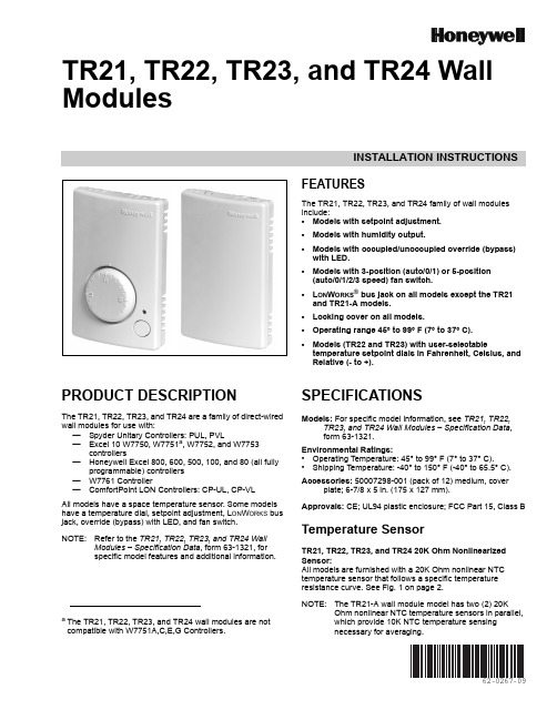
INSTALLATION INSTRUCTIONS62-0267-09TR21, TR22, TR23, and TR24 Wall ModulesFEATURESThe TR21, TR22, TR23, and TR24 family of wall modules include:•Models with setpoint adjustment.•Models with humidity output.•Models with occupied/unoccupied override (bypass) with LED.•Models with 3-position (auto/0/1) or 5-position (auto/0/1/2/3 speed) fan switch.•L ON W ORKS ® bus jack on all models except the TR21 and TR21-A models.•Locking cover on all models.•Operating range 45° to 99° F (7° to 37° C).•Models (TR22 and TR23) with user-selectabletemperature setpoint dials in Fahrenheit, Celsius, and Relative (- to +).PRODUCT DESCRIPTIONThe TR21, TR22, TR23, and TR24 are a family of direct-wired wall modules for use with:—Spyder Unitary Controllers: PUL, PVL—Excel 10 W7750, W7751a , W7752, and W7753controllers—Honeywell Excel 800, 600, 500, 100, and 80 (all fullyprogrammable) controllers —W7761 Controller—ComfortPoint LON Controllers: CP-UL, CP-VL All models have a space temperature sensor. Some models have a temperature dial, setpoint adjustment, L ON W ORKS bus jack, override (bypass) with LED, and fan switch.NOTE:Refer to the TR21, TR22, TR23, and TR24 WallModules – Specification Data , form 63-1321, for specific model features and additional information.SPECIFICATIONSModels: For specific model information, see TR21, TR22,TR23, and TR24 Wall Modules – Specification Data , form 63-1321.Environmental Ratings:•Operating Temperature: 45° to 99° F (7° to 37° C).•Shipping Temperature: -40° to 150° F (-40° to 65.5° C).Accessories: 50007298-001 (pack of 12) medium, coverplate; 6-7/8 x 5in. (175 x 127 mm).Approvals: CE; UL94 plastic enclosure; FCC Part 15, Class BTemperature SensorTR21, TR22, TR23, and TR24 20K Ohm Nonlinearized Sensor:All models are furnished with a 20K Ohm nonlinear NTC temperature sensor that follows a specific temperature resistance curve. See Fig. 1 on page 2.NOTE:The TR21-A wall module model has two (2) 20KOhm nonlinear NTC temperature sensors in parallel, which provide 10K NTC temperature sensingnecessary for averaging.a The TR21, TR22, TR23, and TR24 wall modules are notcompatible with W7751A,C,E,G Controllers.TR21, TR22, TR23, AND TR24 WALL MODULES62-0267—092Fig. 1. Temperature vs. Resistance for Nonlinear Sensor.CommunicationsAll wall modules (except the TR21 and TR21-A models) havea L ON M ARK ® bus communications port. If needed, the jack plug must be removed in the field, and terminals 3 and 4 wired according to the installation instructions.The recommended wire size for the L ON M ARK ® bus is Level IV, 22 AWG (0.34 sq.mm) plenum or non-plenum rated, non-shielded, twisted pair, solid conductor wire.Fig. 2. Wall Module Features (TR23-F Shown).BEFORE INSTALLATIONFailure to follow proper wiring practices canintroduce disruptive electrical interference (noise).Keep wiring at least one foot away from large inductive loads such as motors, line starters, lighting ballasts, and large power distribution panels.Shielded cable is required in installations where these guidelines cannot be met.Ground shild only to grounded controller case.IMPORTANTAll wiring must comply with local electrical codes and ordinances or as specified on installation wiring diagrams.—Wall module wiring can be sized from 16 to 22 AWG (1.31 to 0.33 sq. mm) depending on the application.—The maximum length of wire from a device to a wall module is 1000 ft. (305 m).—Twisted pair wire is recommended for wire runs longer than 100 ft. (30.5 m).INSTALLATIONMount the wall module on an inside wall approximately 54 in. (1372 mm) from the floor (or in the specified location) to allow exposure to the average zone temperature. Do not mount the wall module on an outside wall, on a wall containing water pipes, or near air ducts. Avoid locations that are exposed to discharge air from registers or radiation from lights,appliances, or the sun. See “Cover Disassembly” on page 3.The wall module can be mounted on a wall, on a standard utility conduit box using No. 6 (3.5 mm) screws or on a 60mm wall outlet box (see Fig.3). When mounting directly on a wall, use the type of screws appropriate for the wall material.Fig. 3. Mounting on Standard Utility Conduit Box or60 mm Wall Outlet Box (TR23 Shown).FRONT COVERTR21, TR22, TR23, AND TR24 WALL MODULES362-0267—10Fig. 4. Wall Module Subbase Dimensions in Inches (mm) and Temperature Limit Set Screw Locations (TR23Shown).Cover DisassemblyA snap-fit locking mechanism is used to attach the cover of the wall module to its subbase. To disassemble the cover from the subbase:1.Insert a thin, flat blade screwdriver into each of the twoslots at the bottom of the module to release the two locking tabs. See Fig.2 on page 2.2.Tilt the cover out and away from the subbase to releasethe top two locking tabs.3.To change the dial (e.g. from Fahrenheit to Celsius)release the two tabs on the inside of the front cover and remove the old dial.WiringAttach the wires from the device sensor terminals to the appropriate wall module terminals. See Table 1 on page4.Screw type terminal blocks are designed to accept no more than one 16 AWG (1.31 sq. mm) conductor.Connect multiple wires that are 16-18 AWG(1.31-0.82 sq. mm) with a wire nut. Include a pigtail with this wire group and attach the pigtail to the individual terminal block.Wiring Wall ModulesWire the terminal block as follows:1.For single wires, strip 3/16 in. (5 mm); for multiple wiresgoing into one terminal, strip 1/2 in. (13 mm) insulation from the conductor.2.If two or more wires (20 to 22 AWG only) are beinginserted into one terminal, twist the wires together before inserting. See Fig. 5.3.Insert the wire in the required terminal location and tighten the screw to complete the termination.4.Review and verify the terminal connection wiring and DIP switch settings illustrated in Table 1 on page 4.NOTE:Wire the Lon connection (terminals 3 and 4) usingLevel IV 22 AWG (0.34 mm 2) plenum or non-plenum rated, unshielded, twisted pair, solid conductor wire.Wiring ExamplesTable 1 on page 4 illustrates DIP switch settings and terminal connections for the wall modules. Refer to the TR21, TR22, TR23, and TR24 Wall Modules – Specification Data , form 63-1321, for additional DIP Switch information.IMPORTANTSW 2 on DIP Switch S2 is used for factory calibration of the temperature setpoint potentiometer.Depending on calibration, this switch may be set in either the On or Off position.DO NOT change the position of this switch.NOTES:1.The TR21 and TR22 models do not use DIP Switch S1 and S3.2.DIP Switch S1 is used only on the humidity models, TR21-H and TR23-H.3.Models TR21 and TR21-A use terminals 1 and 2 only. Model TR21-J uses terminals 1, 2, 3, and 4 only.Fig. 5. Attaching Two Wires (20 to 22 AWG) to Wall ModuleTerminals.Attaching the CoverWhen all wiring is complete, attach the cover of the Wall Module as follows:1.Optional : For models with a temperature dial, insert thetwo setpoint screws into the inside of the cover to set the desired temperature range limit. See Fig.4.2.Press the cover straight down onto the subbase until itsnaps into place.3.For models with a temperature dial, insert the desireddial through the opening in the cover. Align the keyed shaft on the knob with the keyed slot into the fitting on the subbase, then press down until it snaps into place.TR21, TR22, TR23, AND TR24 WALL MODULESWiring and DIP switch settings:See Table 1 to determine DIP switch positions and terminal usage for each controller.Table 1. DIP Switch Settings and Terminal Connections.62-0267—094TR21, TR22, TR23, AND TR24 WALL MODULES562-0267—09TR22 and TR23 Setpoint AdjustmentFor the TR22 and TR23 Wall Modules with a setpointadjustment, the controller must be programmed for the values in Table 2 and Table 3.TR23-KL and TR23-H-KLThe TR23-KL and TR23-H-KL ship in packs of 20 and are supplied without setpoint adjustment knobs. Knobs can be ordered separately. See Table 4 for Knob model numbers.Humidity Settings (DIP switch S1)The humidity sensing control mode is set with this 2-position DIP switch. Refer to Fig.4 on page 3 for location of DIP switch S1.NOTE:These switch settings apply only to the TR21-H andTR23-H models.To change the setting, first disconnect the power, then set SW1 and SW2 according to Table 5.TR23 and TR24 Wall Module Override (Bypass) Pushbutton and LED OperationWhen Used With Excel 10 Controllers:The Excel 10 controllers (W7750, W7751, W7752, andW7753) provide timed occupied and unoccupied temperature setpoints for the Wall Module, see Fig. 6. The override pushbutton is used to change the controller into the modes shown in Table 6 and illustrated in Fig.7 on page 6. The override (bypass) LED displays the override status of the controller.Fig. 6. LED and override pushbutton locations(TR23-F Wall Module shown).Table 2. Setpoint Values.Setpoint Value Program Setting55°F (13°C) 2.773 V 65°F (18°C) 2.148 V 75°F (24°C) 1.345 V 85°F (29°C)0.43 VTable 3. Wall Module Setpoint Configuration.Model Setpoint Resistance (Ohms)°F Absolute 55°F 957485°F1426Relative -9°F offset from 70°F 9574+9°F offset from 70°F1426°C Absolute12°C 994530°C1150Table 4. Knob Model NumbersModel DescriptionKNOB-C Celsius scale knob (pack of 20)KNOB-F Fahrenheit scale knob (pack of 20)KNOB-ORelative scale knob (pack of 20)Table 5. DIP Switch S1 Settings.Wall Module Model Sensing Control Individual Switches 12TR21-H TR23-H0-10 Vdc OFF OFF 0-5 Vdc OFF ON 4-20 mAONOFFTR21, TR22, TR23, AND TR24 WALL MODULES62-0267—096Fig. 7. Override pushbutton operation.When Used With Excel 600/500/100/80/50 Controllers:The application engineer/programmer can program theoverride (bypass) and LED to operate in any manner desired. The override (bypass) input is a dry contact, normally open, momentary digital input when the wall module does not have a fan switch. When a fan speed switch (basically a series of resistances based on fan switch position) is present, the override button is an analog input. See Table 4 for resistances.When Used With T7350 Thermostat:TR21, TR21-A, TR21-H, TR22, TR23, and TR24 are the models compatible with the T7350 thermostat. When using with the T7350 thermostat be sure to use the relative +/- offset knob only. The Celsius and Fahrenheit knobs will not work properly with the T7350 Thermostat.TR22-F5, TR23-F3, and TR23-F5 Wall Module Fan SwitchWith the switch in the far left position (Auto), the fanautomatically runs at the speed determined by the controller temperature control algorithm.With the switch in the 0 position, the fan is off. Position 1 is fan speed 1, etc.The wall module fan speed switch overrides the temperature control algorithm.When Used With Excel 10 Controllers:The Excel 10 Controllers (W7750, W7751, W7752, andW7753) can be programmed so that the fan speed switch and override button function the way that the application engineer/programmer wants. See Table 7 for controller-programming resistances. Switch 1 on Dip Switch S2 adds 10k Ohms resistance when OPEN (for Excel 600-80 controllers) and removes it when CLOSED (for Excel 10 controllers).When Used With Excel 600/500/100/80/50 Controllers:Excel 600/500/100/80 Controllers can be programmed so that the fan speed switch and override button function the way that the application engineer/programmer wants. See Table 8 for controller-programming resistances. Switch 1 on Dip Switch S2 adds 10k Ohms resistance when OPEN (for Excel 600-80 controllers) and removes it when CLOSED (for Excel 10 controllers).Table 6. Wall Module Operation.Pushbutton Held Down Controller Model LED Status0 to 1 second No override Off 1 to 4 seconds Timed occupied override On4 to 7 seconds Unoccupied override Single blink per secondLonger than 7 seconds No overrideOffnot applicableContinuous occupied override aaRemote function, which is generated from the network.Two blinks per secondTable 7. Program Settings for Wall Modules withFan Switch using Excel 10 Controllers.For Switch Position Resistance (Ohms)Comment Auto 1861 ±119Left most position 02686 ±127Fan Off position13866 ±13923041 ±13034601 ±146Right most positionOverride button closed Closed circuitTable 8. Program Settings for Wall Modules with Fan Switch using Excel 600/500/100/80 Controllers.For Switch Position Resistance (Ohms)Comment Auto 11.861K ±119Left most position 012.686K ±127Fan Off position113.866K ±139213.04K ±130314.60K ±146Right most positionOverride button closed 10K ±100TR21, TR22, TR23, AND TR24 WALL MODULES 762-0267—09TR21, TR22, TR23, AND TR24 WALL MODULESAutomation and Control Solutions Honeywell International Inc.Honeywell Limited-Honeywell Limitée 1985 Douglas Drive North 35 Dynamic DriveGolden Valley, MN 55422Toronto, Ontario M1V 4Z9® U.S. Registered Trademark© 2009 Honeywell International Inc.62-0267—09E.K. Rev. 09-09L ON W ORKS ® is a registered trademark of Echelon ® Corporation.L ON M ARK ® and the LonMark Logo are trademarks of the LonMark Association.By using this Honeywell literature, you agree that Honeywell will have no liability for any damages arising out of your use or modification to, the literature. You will defend and indemnify Honeywell, its affiliates and subsidiaries, from and against any liability, cost, or damages, including attorneys’ fees, arising out of, or resulting from, any modification to the literature by you.。
霍尼韦尔说明书

霍尼韦尔说明书霍尼韦尔说明书简介霍尼韦尔(Honeywell)是一家全球领先的多元化科技和制造公司,总部位于美国,成立于1906年。
公司的业务涵盖航空航天、楼宇技术、性能材料、可持续性解决方案和安全解决方案等领域。
霍尼韦尔以其创新的技术、高品质的产品和可靠的性能享誉全球。
本文档旨在向用户提供关于霍尼韦尔产品的说明,并介绍如何正确使用和维护这些产品。
产品列表1. 霍尼韦尔智能温控器* 产品名称:霍尼韦尔智能温控器* 产品型号:TH9320WF5003* 产品特点:- 可与智能手机和智能家居系统连接,实现远程控制- 可编程设置温度和计划,提高能源效率- 大屏幕显示温度和湿度等信息* 使用说明:1. 将温控器与电源连接,并按照说明书设置温度和计划。
2. 下载并安装霍尼韦尔智能手机应用。
3. 打开应用,按照提示添加温控器设备。
4. 连接温控器和手机,即可实现远程控制。
2. 霍尼韦尔空气净化器* 产品名称:霍尼韦尔空气净化器* 产品型号:HFD-120-Q* 产品特点:- 高效过滤空气中的颗粒物和有害物质- 自动检测空气质量,并自动调整清洁模式- 低噪音设计,不影响正常生活* 使用说明:1. 将空气净化器放置在需要净化的房间内,并连接电源。
2. 按下电源开关,启动空气净化器。
3. 空气净化器将自动检测空气质量,并根据需要调整清洁模式。
4. 定期更换空气净化器中的滤网,以确保最佳的净化效果。
常见问题与解答Q1:为什么温控器无法连接智能手机?A:请确保智能手机和温控器处于相同的Wi-Fi网络下,并且已经下载并安装了霍尼韦尔智能手机应用。
如果问题仍然存在,请尝试重新连接温控器。
Q2:空气净化器何时需要更换滤网?A:根据使用环境和空气质量,滤网的寿命可能会有所不同。
一般建议每3至6个月更换一次滤网,或者根据空气净化器上的指示灯提示更换。
维护与保养为了保证霍尼韦尔产品的正常运行和延长使用寿命,以下是一些维护与保养的建议:1. 定期检查产品的电源和连接线,确保其无损坏和松动。
Honeywell Dolphin 6110 移动计算机说明书

Mobile Computers F E AT U R E S&B E NE F I T SUltra-lightweight device provides intuitive data entry and comfortable single-handed use ina stylish form factor.Advanced integrated802.11 a/b/g/ntechnology deliversreal-time networkaccess to criticalinformation andsupports advancedwireless securitystandards.Supports both Microsoft®Windows® CE 6.0 andWindows EmbeddedHandheld 6.5 platforms.Adaptus 6.0 imagingtechnology readslinear and 2D barcodesand captures digitalimages and electronicsignatures — enablingworkers to do morewith a single device.Constructedfor use in lightindustrial in-premiseenvironments.The Dolphin 6110 mobile computerprovides advanced data capture andreal-time wireless communication forin-premise applications including pricelookup/audits, inventory management,customer assistance and merchandising.Dolphin 6110Mobile ComputerThe stylish and reliable Honeywell Dolphin™ 6110 mobile computer provides advanced data collection and real-time wireless communication for in-premise applications including price lookup/audits, inventory management, customer assistance and merchandising. Designed with ergonomics in mind, this pocket-sized mobile computer features an angled imager that allows users to view the screen while scanning a barcode.Despite its stylish exterior, the Dolphin 6110 mobile computer wasbuilt to withstand harsh conditions. This IP54-rated device can endure exposure to dust, dirt and splashing water, as well as accidental drops from distances as high as 1.2 meters (4 feet). The high-performing Dolphin 6110 mobile computer can sustain up to 500 tumblesfrom 1 meter (3.3 feet), providing reliability for years to come.Integrated 802.11 a/b/g/n wireless connectivity providesusers with access to critical data throughout the enterprise.A long-lasting battery minimizes the need to change the batteryduring an eight-hour shift, even in wireless, scan-intensive environments. Advanced protocols enhance data security. Userscan also make phone calls using Voice over Internet Protocol (VoIP) technology, eliminating the need to carry additional devices.Powered by Adaptus™ 6.0 imaging technology, the Dolphin 6110mobile computer delivers the broadest suite of advanced datacapture capabilities, including linear and 2D barcode scanning,digital image capture and intelligent signature capture, allowingusers to increase efficiency and improve customer service.Purpose-built for in-premise applications, the Dolphin 6110 mobile computer provides mobile workers with the tools needed to streamline tasks, improve productivity and maximize investment protection.Dolphin 6110 Technical Specifications.Dolphin 6110-DS | Rev D | 08/16© 2016 Honeywell International Inc.For more informationHoneywell Sensing and Productivity Solutions9680 Old Bailes Road Fort Mill, SC 29707800-582-4263For a complete listing of all compliance approvals and certifications, please visit / compliance .For a complete listing of all supported barcode symbologies, please visit / symbologies .Dolphin and Adaptus are registered trademarks or trademarks of Honeywell International Inc. in the U.S. and/or other countries.Microsoft and Windows are either registeredtrademarks or trademarks of Microsoft Corporation in the U.S. and/or other countries.MECHANICALDimensions (L x W x H):With Standard Battery: 175 mm x 69 mm x 39 mm (6.9 in x 2.7 in x 1.5 in)With Extended Battery: 175 mm x 69 mm x 43 mm (6.9 in x 2.7 in x 1.7 in) – includes handstrap At Grip: 58 mm (2.3 in)Weight:Imager: Standard Battery: 247 g (8.7 oz); Extended Battery: 270 g (9.5 oz)Laser: Standard Battery: 252 g (8.9 oz); Extended Battery: 275 g (9.7 oz) – includes handstrapENVIRONMENTALOperating Temperature:Imager: -10°C to 50°C (14°F to 122°F)Laser: -10°C to 40°C (14°F to 104°F)Storage Temperature: -20°C to 70°C (-4°F to 158°F)Humidity: 95% humidity, non-condensing Drop: Withstands multiple 1.2 m (4 ft) drops to concrete, all axis and across operating temperature rangeTumble: 500 1 m (3.3 ft) tumbles (1,000 impacts)ESD: Air: ±15kV; Contact: ±8kVEnvironmental Sealing: Independently certified to meet IP54 standards for moisture and particle resistanceSYSTEM ARCHITECTUREProcessor: Texas Instruments OMAP3715 800 MHzOperating System: Microsoft Windows CE 6.0; Windows Embedded Handheld 6.5.3Memory: 512 MB RAM; 512 MB FlashDisplay: 7.1 cm (2.8 in) transmissive active matrix 65,000-color LCD with backlight, QVGA (240 x 320)Keypad: 28-key shifted alphanumeric with backlit keysAudio: Built-in microphone and speaker, stereo headset jackI/O Ports: High-speed USB v2.0 (480 Mbps)Voice Communication: Voice-over-IP and Push-to-Talk readyApplication Software: Honeywell Power Tools and DemosStorage Expansion: User-accessible Micro SDHC memory card slot. Please check current price guide for available qualified card optionsBattery: Standard: Li-Ion, 3.7V, 2200mAh; Extended: Li-Ion, 3.7V, 3300mAh (includes extended battery door)Expected Hours of Operation: 8+ hours (with scan and continuously transmitting)Expected Charge Time: Standard Battery: 4 hours Extended Battery: 6 hoursImager: Imager: 5603 (Laser Aimer), Standard Range (SR), High Density (HD); Adaptus 6.0imaging technology; Laser: N4313 (only for WEH 6.5 version)Decode Capabilities: Imager: Reads standard 1D and 2D symbologies; Laser: Reads standard 1D symbologiesWarranty: One-year for terminals and peripheralsWIRELESS CONNECTIVITYWLAN: 802.11a/b/g/n, Wi-Fi™ certified WLAN Security:Wi-Fi Alliance Certification, Wireless Security Supplicant (DeviceScape), 802.1x, WPA2, EAP, WEP, LEAP, TKIP, MD5, EAP-TLS, EAP-TTLS, WPA-PSK, PEAP, CCXv4WPAN:Bluetooth® Class II (10 m) v2.1 Enhanced Data Rate(EDR) with on-board antenna. BQB certified。
霍尼韦尔X4使用中文说明书
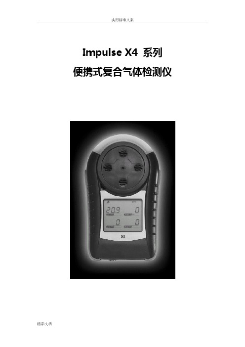
Impulse X4 系列便携式复合气体检测仪操作说明书!重要提示:!在首次使用仪器以前请认真阅读本手册,您将会掌握仪器正确的使用方法和了解仪器的功能,包括操作,维护,功能设置等容。
!为了使操作者更安全,请按照手册中的要求,定期对仪器进行标定。
!如果在使用过程中,遇到的故障或问题在本手册中没有提到,请直接联系制造商Zellweger Analytics,或联系当地的代理商/服务商。
!警告和注意:·更换任何元器件都有可能损坏仪器的本质安全结构。
·如果需要使用存储卡,请选用Zellweger Analytics 提供的存储卡(订货号2566-0435),使用其它的存储卡有可能损坏仪器的本质安全结构。
·在允许的储存期之后激活检测器,有可能影响仪器的使用性能和保质期。
·应使用许可的5号干电池,如劲量电池,不要使用质量低下的干电池,以免影响仪器的本质安全性能。
·在更换电池时,应同时更换2节型号相同的新电池。
·在电池欠压提示后,应尽快更换新电池,以免旧电池漏液损坏仪器。
·在低温环境下,电池的寿命会缩短。
·更换电池时,应该在安全环境下进行。
·当更换任何一个传感器的情况下,都需要对仪器进行标定。
·在每天使用以前,应完成仪器的自检过程。
·定期的对仪器用标气进行测试,检查声、光、振动报警是否正常。
·标定时应选用厂家或国家认证合格企业提供的标准气体。
·标定时应在良好通风的环境下进行,以避免污染。
·不要在仪器电量不足的情况下标定。
·不要在富氧的环境下使用本仪器。
·可燃气体传感器的灵敏度会受到高浓度硫化物,卤素化合物,含硅化合物,以及含铅气体或蒸汽的影响,也叫“中毒”,应避免在以上的环境中使用仪器,如果必须使用,则使用完后应对仪器进行检测和标定,以免影响以后的使用。
- 1、下载文档前请自行甄别文档内容的完整性,平台不提供额外的编辑、内容补充、找答案等附加服务。
- 2、"仅部分预览"的文档,不可在线预览部分如存在完整性等问题,可反馈申请退款(可完整预览的文档不适用该条件!)。
- 3、如文档侵犯您的权益,请联系客服反馈,我们会尽快为您处理(人工客服工作时间:9:00-18:30)。
Honeywell液晶显示器178°宽视角范围
7、宽视角范围 Honeywell液晶显示器采用广视角、高开口率的专业液晶面板 ,可视角度(H/V)达到178°,上下左右超广视角,各角度几乎 没有亮度及彩色的明显变化,并且图像明亮,最适合公共领域的多 角度观看。
10 Document control number Honeywell Proprietary
液晶面板
背光类型 分辨率 亮度(cd/㎡) 对比度 最高色彩 响应时间(ms) 功耗(W) 运行温度(℃)
AUO
LED 1920*1080 450 4000:1 10.7亿色 6.5 185 0℃~40℃
AUO
CCFL 1920*1080 500 5000:1 8bit-16.7Million 8 430 0℃~40℃
Honeywell 显示器专显产品卖点
1、长寿命,支持24小时/天的连续重负载工作 采用A级高性能液晶面板,能够满足7*24小时工作的需要、承 受大幅度的温度变化,更适合长时间显示及公共场所应用。
Honeywell显示器产品
全部采用A级专业显示器液晶面板
13 Document control number Honeywell Proprietary
Honeywell 65寸液晶显示器产品标底文件
1、★国际知名品牌,在国内拥有重点工程的成功案例; 2、★全天候应用设计:投标显示器必须是专为高负荷、全天候显示应用而设计,支持24 小时×7天不间断开机运行; 3、★屏幕尺寸: ≥65寸;液晶背光:采用LED背光源;屏幕亮度:≥500cd/m2;响 应时间:≤4ms;最高色彩:10bit-1.07Billion;物理分辨率:1920×1080 支持全高清 信号显示;对比度:≥4000:1;单边框厚度≤46.5mm 4、★接口满足: 输入:VGA×1、DVI×1、HDMI×1、YPbPr×1、AV×1、DEBUG×1; 控制:RJ45 for RS-485(环接) 5、★平均故障间隔(MTBF):≥60,000小时; 6、★额定功耗≤270W; 7、★所投设备必须满足国内和国际电气设备的安全、电磁学、质量等方面规范和标准; 具备国家3C产品认证证书; 8、★运行温度:0°C~40°C 9、★运行湿度:10~90% 10、投标商须对投标设备的技术性能指标要求给予明确响应; 注:红色★代表重要参数部分
12 Document control number Honeywell Proprietary
Honeywell 显示器专显产品卖点
10、环保健康 Honeywell液晶显示器全部采用最新LED背光技术,低耗电设 计符合国家能效标准节能等级Ⅰ级,不仅大大降低了电力消耗,同 时还减少了发电时产生的CO₂ ,低辐射,无闪烁,不伤眼,不含有 害物质(如铅,汞,镉),是最新一代的环保健康的ol number Honeywell Proprietary
Honeywell 显示器专显产品卖点
5、高对比度显示 Honeywell液晶显示器采用了高级动态对比度技术,使画面更 具层次感,对比度最高可达到4000:1,实现了精细的质感图像。
传热层 - 用特殊薄层进行防热管理 - 比普通LCD TV亮 (1.5倍)
- 7*24小时连续工作保证
- 具有高信赖性
4 Document control number Honeywell Proprietary
Honeywell 显示器专显产品卖点
传统显示,图像灰暗
高级动态对比度技术,图像水平大幅提高
8 Document control number Honeywell Proprietary
Honeywell 显示器专显产品卖点
8bit技术 10bit技术
6、高色彩度显示 Honeywell液晶显示器搭载了新型的10bit液晶技术面板,扩 大了红绿部分的可见光谱,让Honeywell液晶显示器获得了其他 8bit液晶技术更宽的广域的色再现范围,使色彩更丰富、艳丽,充 分享受绚烂多姿的自然界的色彩。
传统8bit面板技术 约16.77百万色彩 最新10bit面板技术 约10.7亿色彩
9 Document control number Honeywell Proprietary
Honeywell 显示器专显产品卖点
传统液晶可视角度变化
Honeywell 显示器专显产品卖点
普通液晶TV显示,亮度300cd/ m2
专业液晶面板显示,亮度700cd/m2
4、高亮度显示 Honeywell显示器产品采用专业高亮液晶面板,拥有更高的亮 度,可达到500-700cd/ m2,比普通液晶TV亮度提高近一倍。
Honeywell 显示器产品介绍
Honeywell 显示器产品线
65寸液晶显示器 70寸液晶显示器 84寸液晶显示器 单屏显示器(3款) HSCL-65HDSS HSCL-70HDSS HSCL-84EHSS
拼接屏显示器(8款) 42寸等离子拼接屏 HSCP-42MS 双边拼缝1.8mm 60寸等离子拼接屏 HSCP-60MS 双边拼缝1.8mm 46寸液晶拼接屏 HSCL-46HDMS 双边拼缝5.5mm,700nit 46寸液晶拼接屏 HSCL-46HDLS 双边拼缝5.5mm,450nit 47寸液晶拼接屏 HSCL-47HDMS 双边拼缝4.9mm,800nit 47寸液晶拼接屏 HSCL-47HDLS 双边拼缝4.9mm,500nit 55寸液晶拼接屏 HSCL-55HDMS 双边拼缝5.3mm,800nit 55寸液晶拼接屏 HSCL-55HDLS 双边拼缝5.3mm,500nit
Honeywell 显示器专显产品卖点
9、超强的环境适应能力 Honeywell显示器产品在防尘、防潮设计上拓展了显示器的使 用范围,增加产品的稳定性,表面的防眩处理,有效地去除变形和 眩光,保持画质的清晰。 Honeywell显示器产品可以保证在的10°至40°的温度环境 下正常运行,湿度运行环境为10%-90%(无凝霜)范围内,优于 同类液晶显示品牌。
20~80%
1378*794*39.4 19.3 32 32000-38000
10~90%
1523*894*80 45.6 54 20000-24000
Honeywell Proprietary
1540.4*909.2*8 1554*924*123. 1675*959.1*64. 8.3 9 8 53.5 52 42000-45000 54 58 55000-60000 23.5 26.8 36000-44000
LED 1920*1080 500 4000:1 10bit1.07Billion 4 270 0℃~40℃
运行湿度(%)
尺寸(mm) 边框尺寸(mm) 重量(kg) 价格区间
15 Document control number
10~90%
10~80%
10~80%
20~80%
1407*817*86 32 38 28000-34000
Honeywell 显示器专显产品卖点
3、极速响应时间 Honeywell显示器产品全部采用新一代液晶驱动技术,使显示 器产品的响应时间缩短到4ms,大大缩短了液晶的拖尾、残影现象 ,达到了市面的液晶产品的领先地位。
6 Document control number Honeywell Proprietary
Honeywell 显示器专显产品卖点
8、专业的连接功能 Honeywell显示器产品具有广泛的连接性能,提供VGA、DVI 、AV、HDMI、YPbPr、DEBUG、RJ45 RS-485等多种接口
11 Document control number Honeywell Proprietary
Honeywell 70寸液晶显示器产品标底文件
1、★国际知名品牌,在国内拥有重点工程的成功案例; 2、★全天候应用设计:投标显示器必须是专为高负荷、全天候显示应用而设计,支持24 小时×7天不间断开机运行; 3、★屏幕尺寸: ≥70寸;液晶背光:采用LED背光源;屏幕亮度:≥700cd/m2;响 应时间:≤4ms;最高色彩:10bit-1.07Billion;物理分辨率:1920×1080 支持全高清 信号显示;对比度:≥4000:1;单边框厚度≤30mm 4、★接口满足: 输入:VGA×1、DVI×1、HDMI×1、YPbPr×1、AV×1、DEBUG×1; 控制:RJ45 for RS-485(环接) 5、★平均故障间隔(MTBF):≥60,000小时; 6、★额定功耗≤430W; 7、★所投设备必须满足国内和国际电气设备的安全、电磁学、质量等方面规范和标准; 具备国家3C产品认证证书; 8、★运行温度:0°C~40°C 9、★运行湿度:10~90% 10、投标商须对投标设备的技术性能指标要求给予明确响应; 注:红色★代表重要参数部分
16 Document control number Honeywell Proprietary
70寸液晶显示器主要进口竞争品牌对比
品牌 产品型号 对角线尺寸 液晶面板 背光类型 分辨率 亮度(cd/㎡) 对比度 最高色彩 响应时间(ms) 功耗(W) 运行温度(℃) NEC P702 70 Samsung CCFL 1920*1080 600 2000:1 三星 700DX-3 70 Samsung CCFL 1920*1080 600 2000:1 三星 ED75C 75 Samsung LED 1920*1080 320 5000:1 10bit1.06Billion 4 490 0℃~40℃ 夏普 PN-E702 70 Sharp LED 1920*1080 450 4000:1 约1064百万色 6 240 0℃~40℃ 夏普 PN-R703 70 Sharp LED 1920*1080 700 4000:1 10.6亿色 6 270 0℃~40℃ Honeywell HSCL-70HDSS 70 Samsung LED 1920*1080 700 4000:1 10bit1.07Billion 4 430 0℃~40℃