SD卡MDR说明书(2011款)
MR08EX SD卡读写器说明书
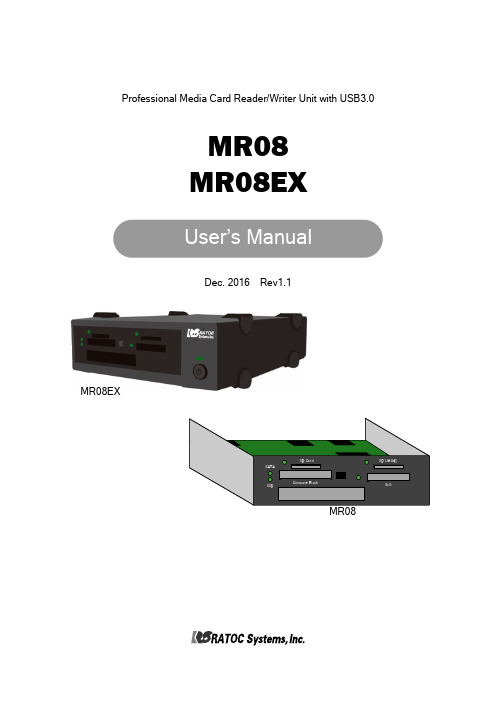
Professional Media Card Reader/Writer Unit with USB3.0MR08MR08EXRev1.1Dec. 2016 MR08EX<Cautions>1.©2016 RATOC Systems, Inc. All rights reserved.2.This user’s manual was created with thorough attention to its content.If, however, you have a question, spot an error, or find a description lacking, please contact us.3.RATOC Systems, Inc. doesn’t take responsibility for any damage arising from the use of this product.4.This publication may not be reproduced or used in whole or in part without permission of RATOC Systems,Inc.5.Design and specifications are subject to change without notice.● “REX” is a trademark owned by RICOH COMPANY, LTD. RICOH allows RATOC Systems,Inc. to use this trademark under license agreement.●SxS、SxS-1、SxS PRO、SxS PRO+ are trademark of Sony Corporation.●Apple、Mac、Mac OS are registered trademarks of Apple Inc. in the United States of America and other countries.●Windows is a registered trademarks of Microsoft Corporation in the United State of America and other countries.●All other product and company names are trademarks or registered trademarks of their respective companies.Introduction41-1.Package Contents------------41-2.System Requirement------------51-3.Supported media------------51-4.Description of each part------------62Setup82-1.Procedure to install this product-------- 82-2.Connection of a USB------------82-3.Installation of HotPlug tool and how to use it ---92-4.Direction of each media insertion---------113Drive letters123-1.Windows10------------123-2.Windows8.1------------123-3.Windows7 ------------134Installation and confirmation inMac OS X15 Thank you for purchasing our product.Be sure to read this user’s manual before using our product.<Features>●This product is a media card reader/writer with USB3.0 interface.●HotPlug tool is included. By this tool, you can centrally manage removal/insertion of all media which this product supports.-1.Package ContentsConfirm all of the items are included in the package.-2.System Requirement●Supported OS:Windows10 / 8.1 / 7 ※Compatible with both 64bit and 32bit OS Mac OS X 10.10 or later●Supported PC:WindowsPC with USB3.0/2.0 ports(It is recommended to connect USB3.0 ports) Mac with USB3.0/2.0-3.Supported media●SD SD memory card, SD memory cardSD High Speed(ver1.1), SD Pro High SpeedSDHC memory card, SDXC memory cardSDXC memory card UHS-I●SxS SxS-1、SxS PRO●CF Compact flash Type I / II、UDMA0~7●SSD SATA2.0(3Gbps) / SATA1.0(1.5Gbps)SD card slot 2, access LED-4.Description of each part UHS-II compatible SD card slot,1-4-1.MR08●Front panel●Back side of PCBAPower connectorMicro-USB port※Be sure to use the SATA cable, and power cable which are attached to this product from the beginning without removing, replacing them.1-4-2.MR08EX●Front panelEach part of memory card is the same as MR08, as described in the previous page.●Back panel2Set up2-1.Procedure to install this productConnect MR08/MR08EX to a PCvia a USB cableSet up HotPlug toolPreparation is complete2-2.Connection of a USB cable 2-2-1.Connection of MR08●It is required to install MR08 into a 5 inch bay of a PC. For further information, please refer to the User’s Manual which accompanies a PC, PC case.●Attach the bundled USB cable into the Micro-B connector of MR08. And connect the USB cable to a PC.●MR08 -----------Page 8●MR08EX-----------Page 9※The bundled HotPlug tool is for the use of Windows only. For Mac, this tool is not required, because standard removal tool in Mac is used instead.●Connect SATA-HDD 15pin power cable to the power connector of MR08.Connected MR08 PCBA alreadyAvailable from power supply unit of a PC2-2-2.Connection of MR08EX2-3-1.Installation of HotPlug toolThis section explains installation of HotPlug tool for Windows and how to use it.Mac users don’t need to install HotPlug tool. Refer to Chapter 2-3-3 for hot-plug instruction.●Before installation of Hot-Plug tool, confirm MR08/MR08EX is connected to the PC.And then, start [ REX-MRHotPlugTool-Setup.exe] at the bundled CD-ROM and follow the on-screeninstructions to finish installation.●Restart the PC. And then, connect MR 08/MR 08EX . And then, the icon will appear at the task tray at the bottom right corner.For Windows users, proceed to Chapter 2-3.Installation of HotPlug tool and how to use it.For Mac users, you have finished installation already.Proceed to Chapter 2-4.Direction of each media insertion and get started with this product.Connected SSD slot already●Connect MR08EX to a PC via a USB cable.2-3-2.How to use HotPlug tool●Click the icon at bottom right.●Black letters mean media which are inserted into the slot now.Gray letters mean media which aren’t inserted into the slot now.●If you click a media you want to remove, it will be ready for removal.Black :2-3-3.HotPlug with Mac●Mac users can hotplug each media by standard function in OS.To remove media, select [Eject] for each media.Gray :Media slot without media●SD Card+Insert SD card with the SD label facing up.+Insert it until it clicks into place.+When removing, push the media again to eject it.2-4. Direction of each media insertion Caution●Be careful of direction of media insertion when each media is inserted.●If media is inserted in the wrong direction, media or MR08/MR08EX may have damaged.Put both connectors at the right side and insert SSD into the slot slowly.●CF Card+Insert CF card with CF label facing up.+Insert it firmly.+When removing, push the eject switch.●SSD+Set the direction of SSD insertion, as shown in the bottom right.+Insert it until some part of SSD goes approx 0.6 inch beyond the front panel.+When removing, pinch the SSD protruding fromthe panel and slide it out slowly.●SxS Card+Insert SxS card with SxS label facing up.+Insert it until some part of SxS card goesapprox 0.6 inch beyond the front panel.+When removing, pinch the SxS protruding from the paneland slide it out slowly.0.6 inch●A drive letter in each media slot will be assigned automatically by Windows after installation of MR08/MR08EX. If drive letters aren’t used, a user can assign any drive letter by following the next steps.●Once the setting is made, Windows will keep the setting, and when Windows starts next time, the assigned drive letter can be used.But, the assigned drive letter may change at the following time:-At the time when a USB port of a PC connected to MR08/MR08EX change.-At the time when a PCIExpress bus slot change if a PCIExpress board for additional USB ports are used.●Right-click at Windows mark at the bottom left corner and select [Disk Management]. Next steps are the same as Windows 7. Proceed to 3-3.Windows 7. 3-1.Windows103Drive letters 3-2.Windows8.1●After selecting [Disk Management], procedure is the same as Windows 7. Proceed to 3-3.Windows 7.●Right-click at [Computer] and click [Manage].●Click [Disk Management] at the [Computer Management] window.3-3.Windows7●Right-click at a drive you want to change, and click the [Change Drive Letter and Paths...].●Select the drive letter and click [Change].●Allocable drive letter will be shown. Select a drive letter and click [OK].●The warning window will appear. Click [Yes].●Drive letter changed to the one you selected.Installation and confirmation in MacOS X4MacOS X(10.10 or later) will load driver software automatically once MR08EX is connected to Mac.∙Select [System information] –[USB]. The screen shown below will appear.This screen shows device information with MR08EX.∙[MR08(SATA-HDD)] appears only when SSD is recognized.。
SanDisk Memory Stick 記憶卡 说明书
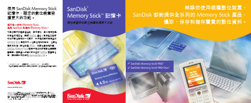
SanDisk 、SanDisk 標誌和Store Your World in Ours (「您的世界由我來存」)是SanDisk Corporation 在美國和其他國家的註冊商標。
Memory Stick 、Memory Stick PRO 、Memory Stick PRO Duo 和MagicGate 是新力(Sony) 公司的商標。
本文中提及的其他品牌名稱僅用於確認,為其各自所屬公司之商標。
© SanDisk Corporation 2006 年版權所有。
保留所有權利。
2006 年1 月第4 次修訂80-11-01309使用SanDisk Memory Stick 記憶卡,讓您的數位裝置發揮更大的功能。
這不是一般的Memory Stick...這是SanDisk 製造的Memory Stick 。
如果您要求的是最佳性能、最好價格、最大儲存容量和完全的相容性,請與SanDisk 連絡。
為滿足您目前和將來數位儲存的一切需求,我們提供業界最完全的Memory Stick 產品系列。
從數位相機到手機,從數位攝影機到個人數位助理(PDA),到數位音樂播放器,SanDisk Memory Stick 記憶卡使您的所有數位裝置盡善盡美。
若需進一步資料或附近的SanDisk 零售商名稱,請瀏覽我們的網站 。
* 1 megabyte (MB) = 1 百萬字元。
1 gigabyte (GB) = 1 千兆字元。
列出的容量有部分需供格式化與其他功能使用,因此並非全部可供資料儲存。
無論您使用哪種數位裝置,SanDisk 都能提供全系列的Memory Stick 產品,攝取、保存和儲存寶貴的數位資料。
SanDisk®Memory Stick ™記憶卡讓您最喜愛的數位裝置發揮最大功能✓SanDisk Memory Stick PRO ™✓SanDisk Memory Stick PRO Duo™最佳性能...最好價格...最大儲存容量...保證相容...唯有SanDisk 出品。
SD卡MDR说明书
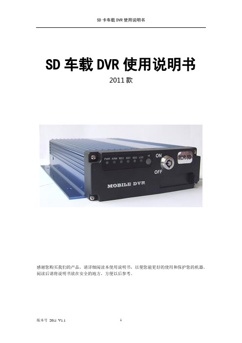
SD车载DVR使用说明书2011款感谢您购买我们的产品。
请详细阅读本使用说明书,以便您能更好的使用和保护您的机器。
阅读后请将说明书放在安全的地方,方便以后参考。
目录1.产品规格 (1)2.产品外特性 (3)32.1 整机外观 (3)32.2 前面板指示灯与接插件定义 (5)32.3 后面板接口定义 (6)32.3外接线缆定义. (7)54.3.1A V音视频输出线缆定义 (7)54.3.2电源线 (7)54.3.3报警输入输出 (8)4.5 主机安装指导 (8)3遥控器功能键说明 (9)4主机功能及操作说明 (11)4.1用户登录 (12)4.2系统设置 (13)4.2.1基本设置 (14)4.2.2开关机设置 (14)4.2.3网络设置 (15)4.2.4密码设置 (16)4.3录像设置 (17)4.3.1常规设置 (17)4.3.2通道设置 (18)4.3.3定时列表 (19)4.3.4子码流设置 (19)4.4行车设置 (20)4.4.1传感器设置 (20)4.4.2速度设置 (21)4.4.3加速度设置 (21)4.5管理工具 (22)4.5.1磁盘管理 (23)4.5.2配置管理 (23)4.5.3系统升级 (24)4.5.4日志管理 (24)4.6录像回放 (25)4.7快捷设置 (25)4.8模块管理 (25)4.9系统信息 (26)5电脑回放录像资料 (27)5.1在电脑上安装播放器 (27)5.2在电脑上使用播放器 (27)1.产品规格SD卡车载主机是专为车载视频监控和远程监控开发的一款高性价比、功能可扩展性强的设备。
它采用高速处理器和嵌入式Linux平台开发,结合IT领域中最先进的H.264视频压缩/解压缩技术。
以SD卡作为存储介质,SD卡车载主机可实现4路CIF、HD1和D1格式的音视频录像、汽车行驶信息记录功能。
SD卡车载主机产品外观简洁、具有超强抗振,安装灵活方便,功能强大,可靠性高等特点。
SD卡使用手册
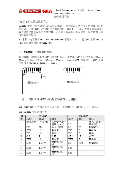
SD卡使用手册第1章 SD软件包使用手册SD/MMC 卡是一种大容量(最大可达4GB)、性价比高、体积帏、访问接口简单的存储卡。
SD/MMC 卡大量应用于数码相机、MP3 机、手机、大容量存储设备,做为这些便携式设备的存储载体,它还具有低功耗、非易失性、保存数据无需消耗能量等特点。
SD 卡接口向下兼容MMC(MutliMediaCard 多媒体卡)卡,访问SD 卡的SPI 协议及部分命令也适用于MMC 卡。
1.1 SD/MMC卡的外部物理接口SD 和MMC 卡的外形和接口触点如图1 所示。
其中SD 卡的外形帺寸为:24mm x 32mm x 2.1mm (普通)或24mm x 32mm x 1.4mm (薄SD 存储卡),MMC 卡的外形帺寸为24mm x 32mm x 1.4mm 。
表1 为SD/MMC 卡各触点的名称及作用,其中MMC 卡只使用了1 ~ 7 触点。
表1 SD/MMC 卡的焊盘分配滨:1. S:电源;I:输入;O:推挽输出;PP:推挽I/O。
2. 扩幕的DAT 线(DAT1 ~ DAT3 )在上电后处于输入状态。
它们在执行SET_BUS_WIDTH 命令后作为DAT 线操作。
当不使用DAT1 ~ DAT3 线时,主机应使自己的DAT1~DAT3 线处于输入模式。
这样定义是为了与MMC 卡保持兼容。
3. 上电后,这条线为带50KΩ上拉电阻的输入线(可以用于检测卡是否存在或选择SPI 模式)。
用户可以在正常的数据传输中用SET_CLR_CARD_DETECT(ACMD42 )命令断开上拉电阻的连接。
MMC 卡的该引脚在SD 模式下为保留引脚,在SD 模式下无任何作用。
4. MMC 卡在SD 模式下为:I/O/PP/OD。
5. MMC 卡在SPI 模式下为:I/PP。
由表1 可见,SD 卡和MMC 卡在不同的通信模式下,各引脚的功能也不相同。
这里的通信模式是指微控制器(主机)访问卡时使用的通信协议,分为两种:SD 模式及SPI 模式。
金士顿优盘、储存卡官方说明书

Kingston's CompactFlash cards have a rated error specification of less than one (1) bit in 1,000,000,000,000,000 bits read, or one (1) bit per 1015 bits read.
3.0 Features of Kingston's Flash Storage Products
Kingston's Flash storage devices offer many advantages for both consumer and industrial applications: Flash Storage Device Warranty: Kingston warrants that its Flash storage devices are free from defects in material and workmanship for the period specified below: SD and CF Cards: Lifetime DataTraveler USB Flash Drives: 5 years MobileLite 9-in1, microSD and Media Readers: 2 years For further details, see /company/warranty.asp Solid State: Flash storage devices, as semiconductor storage devices, have no moving parts and thereby are not subject to the mechanical failure issues of hard drives. Their overall data reliability enabled them to dominate the convenience-oriented portable memory products market, operating silently with a zero decibel noise level. Small Physical Size (or Form Factor): Flash storage devices are designed to be easily transported. Convenience is an important criterion, especially for consumer and corporate applications. High Data Reliability: Flash memory is very reliable and many of the Flash storage device types also include Error Correction Code (ECC) checking to detect single-bit errors.
SD卡详细资料
OCR 位 0-3 4 5 6 7 8 9 10 11 12 13 14 15 16 17 18 19 20 21
VDD 电压范围 保留 1.6~1.7 1.7~1.8 1.8~1.9 1.9~2.0 2.0~2.1 2.1~2.2 2.2~2.3 2.3~2.4 2.4~2.5 2.5~2.6 2.6~2.7 2.7~1.8 2.8~2.9 2.9~3.0 3.0~3.1 3.1~3.2 3.2~3.3 3.3~3.4
OEM/Application ASCII ID(OID) 产品名(PNM) ASCII 产品版本(PRV) BCD
识别卡的 OEM 或卡内容,由制 0x53,0x44 造商分配
40 8
[103:64] [65:56]
5 个 ASCII 字符 2 个二进制编码的十进制数
SD128 产品版本 (30)1
块写操作在DAT0数据线写操作期间使用忙信号,无论用来传输的信号线数目是多少。
命令格式如下所示:
响应标记(token)根据内容不同具有四种格式,标记长度。长度为48位或136位。数 据块的CRC算法采用16位的CCITT多项式。
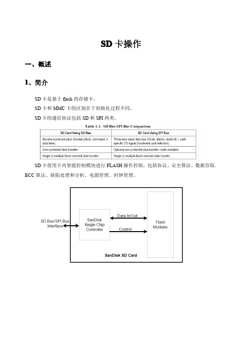
三、SD 卡协议 1 SD 总线协议
SD总线通信是基于命令和数据位流方式的,由一个起始位开始,以一个停止位结束: 命令——命令是开始开始操作的标记。命令从主机发送一个卡(寻址命令)或所有连 接的卡(广播命令)。命令在CMD线上串行传送。 响应——响应是从寻址卡或所有连接的卡(同步)发送给主机用来响应接受到的命令 的标记。命令在CMD线上串行传送。 数据——数据可以通过数据线在卡和主机间双向传送。
3.5 读写操作
Single Block Mode:主机根据事先定义的长度读写一个数据块。由发送模块产生一个 16 位的 CRC 校验码,接受端根据校验码进行检验。读操作的块长度受设备 sector 大小 (512 bytes)的限制,但是可以最小为一个字节。不对齐的访问是不允许的,每个数据块必须位于 单个物理 sector 内。写操作的大小必须为 sector 大小,起始地址必须与 sector 边界对齐。 Multiple Block Mode:主机可以读写多个数据块(相同长度) ,根据命令中的地址读取或 写入连续的内存地址。操作通过一个停止传输命令结束。写操作必须地址对齐。
金士顿移动存储设备说明书
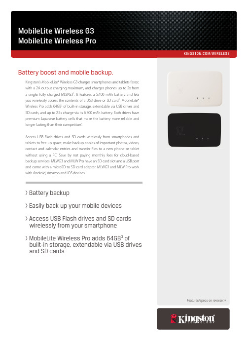
/WIRELESSKingston’s MobileLite® Wireless G3 charges smartphones and tablets faster,with a 2A output charging maximum, and charges phones up to 2x from a single, fully charged MLWG31. It features a 5,400 mAh battery and letsyou wirelessly access the contents of a USB drive or SD card2. MobileLite® Wireless Pro adds 64GB3of built-in storage, extendable via USB drives andSD cards, and up to 2.5x charge via its 6,700 mAh battery. Both drives havepremium Japanese battery cells that make the battery more reliable and longer lasting than their competitors’.Access USB Flash drives and SD cards wirelessly from smartphones andtablets to free up space, make backup copies of important photos, videos, contact and calendar entries and transferles to a new phone or tablet without using a PC. Save by not paying monthly fees for cloud-based backup services. MLWG3 and MLW Pro have an SD card slot and a USB portand come with a microSD to SD card adapter. MLWG3 and MLW Pro workwith Android, Amazon and iOS devices.Battery boost and mobile backup.Features/specs on reverse >>> Battery backup> Easily back up your mobile devices> Access USB Flash drives and SD cards wirelessly from your smartphone> MobileLite Wireless Pro adds 64GB3of built-in storage, extendable via USB drivesand SD cardsCOMPATIBILITY TABLECompatible Mobile Devices8iPad 2/3rd Gen/4th Gen/Air/Air 2 /Pro 9.7” & 12.9”iPad Mini/Mini 2/Mini 3/Mini 4。
MDR-X快速入门指南说明书

TABLE OF CONTENTS Physical Properties (2)Power and Connect (3)Pair MDR-X and Controller (3)Camera Run/Stop (4)AUX Port Modes (5)MDR-X Menu Operation (6)MDR-X Status LEDs (6)PHYSICAL PROPERTIESCOMPATIBLE DEVICES To take advantage of the features and functionality that MDR-X has to offer, you will need to pair the receiver with a compatible Teradek RT controller and configure up to three Teradek RT motors.A: Motor port B: IN-2 port C: IN-1 port D: Power input E: Status LED F: CAM input G: OLED Menu screen H: Menu buttonsConnect the motor(s) to MDR-X’s motor inputs (A) using a 4-pin to 4-pin cable. The motor(s) will then begin calibrating.23Attach the motor(s) to the rods/lens.Connect power to MDR-X’s PWR port (C).1Turn the hand controller on.43POWER AND CONNECT Wireless Pairing via ControllerWireless Pairing via MDR-X Select the same channel number as the controller to begin pairing. Press the MENU button on MDR-X, then navigate to WIRELESS>CHANNEL .21Navigate to WIRELESS>FIND RECV to scan for active receivers and automatically pair. The LED on the controller and receiver will turn green once paired.Press the MENU button on the controller.21PAIR MDR-X AND CONTROLLERIf the controller has not been paired to a receiver, you can use one of the following methods to pair both devices:Press the REC button on the controller to start/stop recording on the camera.2NOTE: If using a RED camera, the camera serial communication setting must be set to RCP (Redlink Command Protocol) for the unit to operate.Connect a camera cable from the CAM port on the MDR-X to the camera, then navigate to MENU>CAMERA to indicate which camera you have connected.1CAMERA RUN/STOP4Connect a 5-pin connector from the controller’s wired-mode input to MDR-X’s IN-1 port (B). The LED on both the controller and MDR-X will turn blue once paired.Wired Pairing (Wired Mode)Press the MENU button on MDR-X, then navigate to the RX CONFIG>IN-1 MODE menu .21Select WIRED mode.35The MDR-X’s status LED indicates when the system is ON and provides the system’s current status during operation.AUX PORT MODESA compatible controller is connected directly to the MDR-X’s IN-1 port, disabling the wireless functionality. The Status LED on both devices will turn BLUE to indicate that a connection has been established.Wired Mode A compatible Slave controller (thumbwheel, zoomrocker, or Smartknob) is connected directly to one of the MDR-X AUX ports, and can be configured to control any available axis (Focus, Iris, etc.).Knob or Rocker Mode (Slave Controllers)AUX port configurationNavigate to RX CONFIG, and select the corresponding mode for the device (Wired , Knob , or Rocker ).Connect a 5-pin cable from the device (controller, smartknob, zoomrocker, or thumbwheel) to one of MDR-X’s AUX ports.21MDR-X STATUS LEDS• OFF - Unit is powered off • YELLOW - No wireless connection • RED - Camera is recording • ORANGE - PC/Bootloader mode • WHITE - Checking RF module status • GREEN - Wireless connection established • BLUE - Wired-mode connection establishedPress the MENU button, then use the ▲, ▼ and SET button to navigate through the different menu options.• MOTORS - Configure the attached motor(s)• CAMERA - Select the make of the camera • WIRELESS - Configure wireless settings • SCREEN - Change OLED settings • BUTTONS - Assign functions to the buttons • RX CONFIG - Assign a specific function (MODE) or class (AXIS) to the receiver’s auxiliary port(s)• STATUS - Check the status of any accessories, controllers, and motors connected to MDR-X • ADV - Obtain information about the receiver and perform essential system functions such as factory resetMDR-X MENU OPERATION6Teradek regularly releases new firmware versions to improve performance, add new features, or to fix vulnerabilities. Visit https:// to update your device with the latest firmware.SUPPORT: → Contains tips, information and all the latest firmware & software updates. TERADEK SUPPORT STAFF:****************************************.2(Mon-Fri6amto 6pm PST)NEED MORE HELP?。
- 1、下载文档前请自行甄别文档内容的完整性,平台不提供额外的编辑、内容补充、找答案等附加服务。
- 2、"仅部分预览"的文档,不可在线预览部分如存在完整性等问题,可反馈申请退款(可完整预览的文档不适用该条件!)。
- 3、如文档侵犯您的权益,请联系客服反馈,我们会尽快为您处理(人工客服工作时间:9:00-18:30)。
SD车载DVR使用说明书2011款感谢您购买我们的产品。
请详细阅读本使用说明书,以便您能更好的使用和保护您的机器。
阅读后请将说明书放在安全的地方,方便以后参考。
目录1.产品规格 (3)2.产品外特性 (5)2.4外接线缆定义. (7)2.4.1 AV音视频输出线缆定义 (7)4遥控器功能键说明 (9)4主机功能及操作说明 (11)3.用户登录 (12)3.系统设置 (13)4.2.1基本设置 (14)4.2.2开关机设置 (14)4.2.3网络设置 (15)4.2.4密码设置 (16)3.录像设置 (17)4.3.1常规设置 (17)4.3.2通道设置 (18)4.3.3定时列表 (19)4.3.4子码流设置 (19)3.行车设置 (20)4.4.1传感器设置 (20)4.4.2速度设置 (21)4.4.3加速度设置 (21)3.管理工具 (22)4.5.1磁盘管理 (23)4.5.2配置管理 (23)4.5.3系统升级 (24)4.5.4日志管理 (24)3.录像回放 (25)4.7快捷设置 (25)4.8模块管理 (25)4.9系统信息 (26)5电脑回放录像资料 (27)5.1在电脑上安装播放器 (27)5.2在电脑上安装播放器 (27)1.产品规格SD卡车载主机是专为车载视频监控和远程监控开发的一款高性价比、功能可扩展性强的设备。
它采用高速处理器和嵌入式Linux平台开发,结合IT领域中最先进的H.264视频压缩/解压缩技术。
以SD卡作为存储介质,SD卡车载主机可实现4路CIF、HD1和D1格式的音视频录像、汽车行驶信息记录功能。
SD卡车载主机产品外观简洁、具有超强抗振,安装灵活方便,功能强大,可靠性高等特点。
SD卡车载主机的产品规格见表1。
表1:SD卡车载主机产品规格列表SD卡车载主机的基本电气参数如表2。
表2:SD卡车载主机基本电气参数列表2.产品外特性2.1.整机外观整机外观如图1所示图1:SD卡车载主机整机外观2.2.前后面板指示灯与接插件定义如图2所示图2:前面板指示灯图前面板接口定义如下表。
2.3. 后面板接口定义如图3所示图3:后面板接口图后面板接口定义如下表。
2.4 外接线缆定义.2.4.1 AV音视频输出线缆定义图4 AV音视频线缆接口示意图2.4.2电源线电源线如图4所示,一端是6PIN白色插头,接在设备后面板的6PIN白色接头上。
红线和黑线直接接到汽车的电瓶上。
红线接正极,黑线接负极。
黄线接点火线,主机设备在汽车打开车钥匙后自动开启,关闭车钥匙后自动延时关闭。
黄线接在车钥匙打开所有仪表盘灯时的那个档位(就是汽车启动马达之前的那个档位)。
注意:1)连接前需要确认电瓶的电压在8V—36V之间,否则超过会烧坏设备;2)连接好线后,要注意电源线之间的绝缘,防止电源线短路烧坏电瓶防。
3)黄线一定要接在点火线上,否则设备将不支持延时关机,最后的录像视频将丢失。
4)注意:车载机安装一定得从电瓶直接取正负极,不能用搭铁做地线,搭铁会产生负脉冲干扰主机的正常运行。
正负极采用的电源线线径必须为Φ1.5mm以上。
图5 电源输入线缆实物图3.报警输入输出设备有6个报警输入接口和2个报警输出接口。
报警输入检测都是电平检测,可接各种车辆行车状态,比如刹车、转向喇叭等等。
刹车检测示意图如下图所示,当刹车板踩下时,SD 卡车载主机就能检测到高电平,否则检测到低电平。
报警输出都是电平输出,驱动能力为200mA ,如果要驱动功率比较大的器件,必须外接继电器。
报警输出光电报警接线示意图如下图所示。
3.主机安装指导A. 开箱及附件检查开箱后请检查主机是否有变形或其它性质的损坏,如有以上现象存在请停止使用并与您的供应商取得联系。
B. SD 卡安装SD 卡在主板上,从主机前端可以插入SD 卡。
将SD 卡对准SD 卡口按压到位(插入SD 卡时注意正反面,反面向上)。
SD卡车载主机报警载主机传感器输入线刹车灯+24V4 遥控器功能键说明SD卡车载主机产品面板上没有直接的控制按钮,需要使用遥控器配合操作。
遥控器按键及功能介绍:1.数字键区:【0-9】键:在设置状态下,数字输入键用于选择数字。
在回放和预览时,1、2、3、4键用于通道之间的切换【+】、【-】键:调整数字增加或减少时使用。
2.设置菜单导航:,:上、下光标方向移动键;,:左、右光标方向移动键;【ENTER】键:在设置状态下,表示选择和保存;在回放状态下,按ENTER键可在屏幕上显示OSD OVERLAY菜单中选择ON的参数。
3.其它功能键:表8 遥控器其他按键的说明4 主机功能及操作说明系统包括八个模块:系统设置、录像设置、行车记录、常用工具、录像回放、快捷设置、模块管理、系统信息。
主菜单如图5所示,功能结构如图6所示。
说明:1、以下所有子菜单的设置,都必须在确认【保存】后生效,否则设置无效。
2、复选框□被填充表示选中某功能,未被填充表示不选中某功能。
3、数字输入可以按遥控器上的数字键直接输入或使用软键盘。
字母输入则必须通过软键盘完成,子菜单返回按RETURN键。
图6:主菜单功能结构3.用户登录电源线接好后,按遥控器上的LOGIN键直接进入登录界面如图7所示:图7:登录界面说明:1. 设备号:用户给每台设备设置机号,登录时会自动显示在编号输入框的右边,用户按显示的数字原样输入即可;当设备号为空2. 用户名:包括admin(管理员)和user(普通用户),以用户身份登录,只能进入查找、信息菜单,不能进入设置菜单设置参数。
以管理员身份登录,可以进行参数的设置3. 密码:根据选择的用户名输入相应的密码,。
当密码正确时,选向下键再按登录即可;密码不正确时,显示提示信息,先按向上键,再按CANCEL后重输正确密码。
用户密码的初始设置为6个1,管理员密码的初始设置为6个1。
3.系统设置系统设置界面包含四个功能选项:基本设置、开关机设置、网络设置和密码设置,如图8所示。
图8:系统设置4.2.1 基本设置主要对系统时间以及设备的一些基本属性进行设置,如图9所示。
图9:基本设置说明:1.日期格式:按ENTER能够切换日期的输出格式(年月日和日月年)。
2.日期时间设置时,请先按ENTER,再按+或-键,最后按ENTER。
3.操作超时和设备号设置时,请先按CANCEL,再按数字键。
4.公司名称、车牌号码、司机姓名和线路号设置时:ENTER—向右键—向下键—Back —中/EN;如输入中文先输中文的第一个字母会出现1—5,按数字键进行选择;如没有此字的拼音,再按REW/FWD 进行选择—RETURN。
5.当开启自动校时后,选择所在时区,当到达校时时间栏内输入的时间点时系统会自动通过GPS校时。
4.2.2 开关机设置开关机设置界面如图10所示图10:开关机设置说明:1.开关机模式: 点火模式和定时模式,开关机模式按ENTER切换选择。
点火模式即汽车发动后DVR就自动开机,定时模式即在用户设定的时间点开机。
2.延时关机设置:当用户选择点火模式时,还可以选择是否延时关机,如果开启延时关机,那么用户可以设置延时时长,设定完后,汽车熄火后DVR会继续录像延时长的时间,延长时间设置先按CANCEL再按数字键(注:时间范围是3—240分钟)。
如设置值不在这个范围内,系统会提示。
3.定时开关机时间:当用户的开关机模式选在定时时,需要在这里设置定时的时间,设定完保存后,DVR会在这个所设置的这个时间点关开机。
4.2.3 网络设置网络设置界面如图11所示图11:网络设置说明:1.本地网络:本地网络为用有线宽带上网时使用。
主要是测试时用,在DVR的运行中极少用到,用户可以不用去关注。
IP地址、掩码和网关的设置均是先按CANCEL ,再按数字键依次更改;MAC地址的设置按ENTER键,进入软件盘。
先按方向键,再按ENTER键输入所要的地址。
3.中心设置:服务器IP设置成CMS中心服务器的IP,控制端口设置成网关服务器的端口号,一般设置为8501;服务器IP、控制端口设置是先按CANCEL——数字键4.2.4密码设置密码设置界面如图12所示图12:密码设置说明:1、密码有效设置可选择开启或关闭。
2、用户密码和管理员密码均只有管理员有权限修改,修改时请先按CANCEL—数字键—保存—RETURN。
3.录像设置录像设置:常规设置、通道设置、定时设置、子码流设置。
如图13所示图13:录像设置4.3.1 常规设置常规设置界面如图14所示图14:常规设置说明:1.视屏制式请按ENTER键可选择PAL/NTSC。
2.录像模式请按ENTER键可选择开机录像/报警录像/定时录像。
3.分段时间请按ENTER键可选15/30/45/60,即录像时每这么长时间段打包一次。
4.自动覆盖按ENTER键可选择开启/关闭,当开启时如果SD卡存满时,后面的录像会自动覆盖最早时间的录像。
5.报警预录时间是指报警发生时,会把报警之前的这段时长的录像打包到报警录像里,设置请先按CANCEL再按数字键(时间范围0S-- 60S)。
6.报警录像延时(秒)是指报警停止后,会把报警停止后的这段时长的录像打包到报警录像里设置请先按CANCEL再按数字键(延时范围30—900)。
7.报警输出时间(秒)设置请先按CANCEL再按数字键(5S---240S)。
8.报警录像保护时间即报警录像在SD卡里存储的时长,在保护时间内,就算SD卡满了报警录像也不会被覆盖掉,按ENTER键可选1/3/5/7/10/15。
9.录像记录行车信息开启/关闭,当开启时,主要是记录报警信息,gps信息等等。
是和录像一起写到录像里面的,通过回放分析软件可以查看到这些信息。
4.3.2 通道设置通道设置界面如图15所示图15:通道设置说明:1.有四路视频通道,可以对每个通道的一些属性进行设置,分辨率可选D1/HD1/CIF,帧率(01----30可选)、画质(1---8),其中画质1为最高清;在设置属性时均按ENTER键进行选择。
4.3.3 定时列表图16:定时设置说明:1.如果图14中的录像模式选择“定时录像”需要在这里设置定时的时间段。
设置时请先按数字组的减号键再按数字键,按加号键再按数字键依次对时间段1每一时刻进行设置。
按向右键按照时间段1的方法设置时间段2。
4.3.4 子码流设置图17:字码流设置说明:1.比特率设置可选16/24/32/40/48/56/64/72/80/96/128/160/200/256/384,这里设置的比特率为一个通道的传输速率。
2.帧率设置可选01/02/03/04/05/07/10/13/15/20/23/25。
3.行车设置行车记录:传感器设置、速度设置、冲击设置、温度设置。
图18:行车记录设置4.4.1传感器设置图19:传感器设置说明:1.用户根据安装DVR时设置的不同接口而自定义传感器名称;按enter键后可以使用软键盘输入对应的名称。