MPU9250规格书
AD9250参数配置的程序(AD9250 参数配置 + Xilinx Kintex

AD9250参数配置的程序(AD9250 参数配置 + Xilinx Kintex1 设计简介本次的demo设计将通过上位机的设置界面,完成AD9250的参数设置。
界面通过USB2.0控制器Cy68013完成数据AD9250的配置工作。
AD9250的参数配置是通过SPI的接口完成,SPI的接口由3个IO组成:the serial clock pin SCLK:n SCLK的为时钟IO,其最高的工作频率为25MHz,并接50K的下拉电阻。
the serial data input/output pin SDIO。
n SDIO为数据传输的双向IO口,在AD9250中,SDIO的初始状态为输入IO,在获取读写命令后,IO的输入输出方向将会发生相应的变化。
the chip select bar pin CSB。
n 片选信号,低电平有效。
根据AD9250的配置参数的特性,配置的参数可以分为4个部分:ConfigurationregisterTransfer registerProgram registerJESD204B link setup parameter2 SPI接口时序SPI的时序如图所示,数据在CSB拉低时有效,并在SLCK的第一个上升沿开始SPI的数据传输。
数据在SCLK的下降沿进行更新,在SCLK的上升沿进行数据的读取。
数据的具体格式为:数据帧的第1bit的为读写控制信号,Read为1,wirte为0.数据帧的第2bit和第3bit为地址信号n W1W0 = 11:数据帧的长度不限,在CSB为低时将一直传输数据n W1W0 = 10:数字帧的数据长度为3n W1W0 = 01:数字帧的数据长度为2n W1W0 = 00:数字帧的数据长度为1数据帧的第4-16bit:访问AD的内存地址。
有效空间为0-255。
后续为写入或者读出的AD的控制数据。
3 参数配置参数可以根据其功能的不同,分为4个部分进行介绍:Configuration registern Global SPI config:LSB first 、Soft resetTransfer registern Transfer settings:该位置1表示将Program registernJESD204B link setup parameter1. Disable lanes before changingconfiguration2. Select quick configurationoption3. Configure detailed options4. Check FCHK, checksum ofJESD204B interface parameters5. Set additional digital outputconfiguration options6. Re-enable lane(s)4 配置流程//配置AD9250的寄存器的工作方式write(5F, 15); //204B link control,powerdown JESD204B link,ilas test modeWrite(0B,01); //选择时钟的分频系数Write(FF,01); //将写入的控制数据统一更新,该功能可以让输入的控制数据在向0xFF写1后统一获得更新。
MPU-9250 九轴产品中文说明书
3.6 SPI 时序特性.....................................................................................................................16
4 使用说明......................................................................................................................................19
3.4.1 D.C.电气特性 .........................................................................................................11
3.4.2 A.C.电气特性 .........................................................................................................12
4.13 MPU-250 I2C 通信解决方案 ..........................................................................................25
4.14 MPU-9250 SPI 通信解决方案.........................................................................................26
3.4.3 其他特性.......................................................................................................................14
INFIN飞控简介

面向无人机的英飞凌解决方案英飞凌推出经济实惠, 高性价比的全新系统解决方案,并确保卓越的用户体验/multicopter近年来,无人机取得了长足的进展,从玩具演变成可用于娱乐,航拍,运输,对海洋, 高压线路,灾情及气象等进行监视。
这为无人机制造商带来了挑战和机遇。
英飞凌为这个快速发展的市场提供经济划算的系统解决方案,提供卓越体验并满足最终用户的要求,如减轻重量,延长飞行时间,确保安全性和可靠性等等。
行业领先的无人机解决方案无人机解决方案英飞凌科技(奥地利)股份公司印制9500 Villach, Austria© 英飞凌科技股份公司版权所有,2016年。
保留所有权利订购编号:B131-I0171-V2-7600-EU-EC-P 日期:2016年3月请注意!本文档仅供参考,不论在任何情况下,文中给出的任何信息均不应被视作关于英飞凌产品的任何功能, 状况和/或质量, 或者适于特定用途的担保, 保证或描述。
关于英飞凌产品的技术规格,惠请参考英飞凌提供的有关产品数据表。
客户及其技术部门应当自行评估英飞凌产品用于其目标应用的适用性。
英飞凌保留随时更改本文档和/或文中给出信息的权利。
更多信息关于技术, 英飞凌产品, 英飞凌产品的应用, 交付条款和条件和/或价格的更多信息,请垂询距离您最近的英飞凌科技办事处()。
警告出于技术要求,英飞凌产品可能含有危险物质。
关于有关危险物质类型的信息,请垂询距离您最近的英飞凌科技办事处。
除英飞凌以经英飞凌科技授权代表签署的书面文件形式明确同意的之外,英飞凌产品不得用于任何存在生命危险的应用, 包括但不限于,医疗, 核, 军事或生命关键型设备,或者英飞凌产品故障或使用英飞凌产品造成的任何后果可能导致人身伤害的任何其他应用。
准备实现IMU,以用于评估和教学关于XMC4500演示板的更多信息,请访问: /demo-xmc45001. LV MOSFET:BSC0942NDI双MOSFET2. 驱动器:IR23013. 电子速度控制器(ESC):XMC1302,XMC1100,配备IRMCK0994. 高分辨率传感器,用于高度控制DPS3105. 飞行控制器:XMC45006. 电池认证:SLE950507. LED驱动器:BCR320U8. 板载调试器:XMC42009. IMU Invensense:MPU9250123。
MPU-9250 九轴产品中文说明书
4.9 运动数字处理引擎(DMP)...........................................................................................23
4.10 主 I2C 及 SPI 通信..........................................................................................................23
4.17 FIFO 数据缓存区 ............................................................................................................27
4.15 时钟方案........................................................................................................................26
4.16 数据寄存器....................................................................................................................27
4.13 MPU-250 I2C 通信解决方案 ...................................................................................PI 通信解决方案.........................................................................................26
MPU9250配置例程
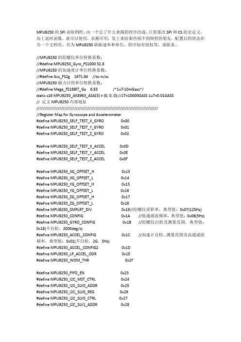
MPU9250的SPI读取例程,由一个忘了什么来源的程序改成,只需要改SPI和CS的宏定义,加上延时函数,就可以使用,亲测可用,发上来给那些找不到例程的朋友,配置后的状态在另一个文档里,名为MPU9250刷新速率和单位,程序如有侵权等,请联系…//MPU9250的陀螺仪单位转换系数://#define MPU9250_Gyro_FS1000 32.8//MPU9250的加速度计单位转换系数://#define Acc_FS2g 1671.84 //to m/ss//MPU9250磁力计的单位转换系数://#define Mega_FS16BIT_Ga 6.83/*1uT-10mGass*/static s16 MPU9250_AK8963_ASA[3] = {0, 0, 0};//1T=10000GASS 1uT=0.01GASS// 定义MPU9250内部地址////////////////////////////////////////////////////////////////////////////Register Map for Gyroscope and Accelerometer#define MPU9250_SELF_TEST_X_GYRO 0x00#define MPU9250_SELF_TEST_Y_GYRO 0x01#define MPU9250_SELF_TEST_Z_GYRO 0x02#define MPU9250_SELF_TEST_X_ACCEL 0x0D#define MPU9250_SELF_TEST_Y_ACCEL 0x0E#define MPU9250_SELF_TEST_Z_ACCEL 0x0F#define MPU9250_XG_OFFSET_H 0x13#define MPU9250_XG_OFFSET_L 0x14#define MPU9250_YG_OFFSET_H 0x15#define MPU9250_YG_OFFSET_L 0x16#define MPU9250_ZG_OFFSET_H 0x17#define MPU9250_ZG_OFFSET_L 0x18#define MPU9250_SMPLRT_DIV 0x19//陀螺仪采样率,典型值:0x07(125Hz) #define MPU9250_CONFIG 0x1A//低通滤波频率,典型值:0x06(5Hz) #define MPU9250_GYRO_CONFIG 0x1B//陀螺仪自检及测量范围,典型值:0x18(不自检,2000deg/s)#define MPU9250_ACCEL_CONFIG 0x1C//加速计自检、测量范围及高通滤波频率,典型值:0x01(不自检,2G,5Hz)#define MPU9250_ACCEL_CONFIG2 0x1D#define MPU9250_LP_ACCEL_ODR 0x1E#define MPU9250_WOM_THR 0x1F#define MPU9250_FIFO_EN 0x23#define MPU9250_I2C_MST_CTRL 0x24#define MPU9250_I2C_SLV0_ADDR 0x25#define MPU9250_I2C_SLV0_REG 0x26#define MPU9250_I2C_SLV0_CTRL 0x27#define MPU9250_I2C_SLV1_ADDR 0x28#define MPU9250_I2C_SLV1_CTRL 0x2A #define MPU9250_I2C_SLV2_ADDR 0x2B #define MPU9250_I2C_SLV2_REG 0x2C #define MPU9250_I2C_SLV2_CTRL 0x2D #define MPU9250_I2C_SLV3_ADDR 0x2E #define MPU9250_I2C_SLV3_REG 0x2F #define MPU9250_I2C_SLV3_CTRL 0x30 #define MPU9250_I2C_SLV4_ADDR 0x31 #define MPU9250_I2C_SLV4_REG 0x32 #define MPU9250_I2C_SLV4_DO 0x33 #define MPU9250_I2C_SLV4_CTRL 0x34 #define MPU9250_I2C_SLV4_DI 0x35 #define MPU9250_I2C_MST_STATUS 0x36 #define MPU9250_INT_PIN_CFG 0x37 #define MPU9250_INT_ENABLE 0x38#define MPU9250_INT_STATUS 0x3A #define MPU9250_ACCEL_XOUT_H 0x3B #define MPU9250_ACCEL_XOUT_L 0x3C #define MPU9250_ACCEL_YOUT_H 0x3D #define MPU9250_ACCEL_YOUT_L 0x3E #define MPU9250_ACCEL_ZOUT_H 0x3F #define MPU9250_ACCEL_ZOUT_L 0x40 #define MPU9250_TEMP_OUT_H 0x41 #define MPU9250_TEMP_OUT_L 0x42 #define MPU9250_GYRO_XOUT_H 0x43 #define MPU9250_GYRO_XOUT_L 0x44 #define MPU9250_GYRO_YOUT_H 0x45 #define MPU9250_GYRO_YOUT_L 0x46 #define MPU9250_GYRO_ZOUT_H 0x47 #define MPU9250_GYRO_ZOUT_L 0x48 #define MPU9250_EXT_SENS_DATA_00 0x49 #define MPU9250_EXT_SENS_DATA_01 0x4A #define MPU9250_EXT_SENS_DATA_02 0x4B #define MPU9250_EXT_SENS_DATA_03 0x4C #define MPU9250_EXT_SENS_DATA_04 0x4D #define MPU9250_EXT_SENS_DATA_05 0x4E #define MPU9250_EXT_SENS_DATA_06 0x4F #define MPU9250_EXT_SENS_DATA_07 0x50 #define MPU9250_EXT_SENS_DATA_08 0x51 #define MPU9250_EXT_SENS_DATA_09 0x52 #define MPU9250_EXT_SENS_DATA_10 0x53 #define MPU9250_EXT_SENS_DATA_11 0x54#define MPU9250_EXT_SENS_DATA_13 0x56#define MPU9250_EXT_SENS_DATA_14 0x57#define MPU9250_EXT_SENS_DATA_15 0x58#define MPU9250_EXT_SENS_DATA_16 0x59#define MPU9250_EXT_SENS_DATA_17 0x5A#define MPU9250_EXT_SENS_DATA_18 0x5B#define MPU9250_EXT_SENS_DATA_19 0x5C#define MPU9250_EXT_SENS_DATA_20 0x5D#define MPU9250_EXT_SENS_DATA_21 0x5E#define MPU9250_EXT_SENS_DATA_22 0x5F#define MPU9250_EXT_SENS_DATA_23 0x60#define MPU9250_I2C_SLV0_DO 0x63#define MPU9250_I2C_SLV1_DO 0x64#define MPU9250_I2C_SLV2_DO 0x65#define MPU9250_I2C_SLV3_DO 0x66#define MPU9250_I2C_MST_DELAY_CTRL 0x67#define MPU9250_SIGNAL_PATH_RESET 0x68#define MPU9250_MOT_DETECT_CTRL 0x69#define MPU9250_USER_CTRL 0x6A#define MPU9250_PWR_MGMT_1 0x6B//电源管理,典型值:0x00(正常启用) #define MPU9250_PWR_MGMT_2 0x6C#define MPU9250_FIFO_COUNTH 0x72#define MPU9250_FIFO_COUNTL 0x73#define MPU9250_FIFO_R_W 0x74#define MPU9250_WHO_AM_I 0x75//ID寄存器(默认数值0x71,只读) #define MPU9250_XA_OFFSET_H 0x77#define MPU9250_XA_OFFSET_L 0x78#define MPU9250_YA_OFFSET_H 0x7A#define MPU9250_YA_OFFSET_L 0x7B#define MPU9250_ZA_OFFSET_H 0x7D#define MPU9250_ZA_OFFSET_L 0x7E//#define MPU9250_I2C_READ 0x80//Magnetometer register maps#define MPU9250_AK8963_WIA 0x00#define MPU9250_AK8963_INFO 0x01#define MPU9250_AK8963_ST1 0x02#define MPU9250_AK8963_XOUT_L 0x03#define MPU9250_AK8963_XOUT_H 0x04#define MPU9250_AK8963_YOUT_L 0x05#define MPU9250_AK8963_YOUT_H 0x06#define MPU9250_AK8963_ZOUT_L 0x07#define MPU9250_AK8963_ZOUT_H 0x08#define MPU9250_AK8963_ST2 0x09#define MPU9250_AK8963_CNTL 0x0A#define MPU9250_AK8963_CNTL2 0x0B#define MPU9250_AK8963_RSV 0x0B //DO NOT ACCESS <MPU9250_AK8963_CNTL2>#define MPU9250_AK8963_ASTC 0x0C#define MPU9250_AK8963_TS1 0x0D //DO NOT ACCESS#define MPU9250_AK8963_TS2 0x0E //DO NOT ACCESS#define MPU9250_AK8963_I2CDIS 0x0F#define MPU9250_AK8963_ASAX 0x10#define MPU9250_AK8963_ASAY 0x11#define MPU9250_AK8963_ASAZ 0x12#define MPU9250_AK8963_I2C_ADDR 0x0C#define MPU9250_AK8963_POWER_DOWN 0x10#define MPU9250_AK8963_FUSE_ROM_ACCESS 0x1F#define MPU9250_AK8963_SINGLE_MEASUREMENT 0x11#define MPU9250_AK8963_CONTINUOUS_MEASUREMENT 0x16 //MODE2刷新速率100Hz#define MPU9250_AK8963_DATA_READY (0x01)#define MPU9250_AK8963_DATA_OVERRUN (0x02)#define MPU9250_AK8963_OVERFLOW (0x80)#define MPU9250_AK8963_DATA_ERROR (0x40)#define MPU9250_AK8963_CNTL2_SRST 0x01//#define MPU9250_I2C_SLV4_EN 0x80#define MPU9250_I2C_SLV4_DONE 0x40#define MPU9250_I2C_SLV4_NACK 0x10//#define MPU9250_I2C_IF_DIS (0x10)#define MPU9250_I2C_MST_EN (0x20)#define MPU9250_FIFO_RST (0x04)#define MPU9250_FIFO_ENABLE (0x40)//#define MPU9250_RESET 0x80#define MPU9250_CLOCK_MASK 0xF8#define MPU9250_CLOCK_INTERNAL 0x00#define MPU9250_CLOCK_PLL 0x01#define MPU9250_CLOCK_PLLGYROZ 0x03#define MPU9250_FS_SEL_MASK 0xE7#define MPU9250_SLEEP_MASK 0x40//#define MPU9250_XYZ_GYRO 0xC7#define MPU9250_XYZ_ACCEL 0xF8//#define MPU9250_RAW_RDY_EN (0x01)#define MPU9250_RAW_DATA_RDY_INT (0x01)#define MPU9250_FIFO_OVERFLOW (0x10)//#define MPU9250_INT_ANYRD_2CLEAR (0x10)#define MPU9250_LATCH_INT_EN (0x20)//#define MPU9250_MAX_FIFO (1024)#define MPU9250_FIFO_SIZE_1024 (0x40)#define MPU9250_FIFO_SIZE_2048 (0x80)#define MPU9250_FIFO_SIZE_4096 (0xC0)#define MPU9250_TEMP_OUT (0x80)#define MPU9250_GYRO_XOUT (0x40)#define MPU9250_GYRO_YOUT (0x20)#define MPU9250_GYRO_ZOUT (0x10)#define MPU9250_ACCEL (0x08)//////////////////////////////////////////////////////////////////////////#define SMPLRT_DIV 0#define MPU9250_SPIx_ADDR 0x00/****************************************************************************** /#define MPU9250_SPI_ReadWriteByte(x)SPI1_ReadWriteByte(x)#define MPU9250_CS_LGPIO_ResetBits(GPIOA,GPIO_Pin_4)#define MPU9250_CS_HGPIO_SetBits(GPIOA,GPIO_Pin_4)/****************************************************************************** ///////////////////////////////////////////////////////////////////////////enum MPU9250_GYRO_DLPF{MPU9250_GYRO_DLPF_250HZ = 0,MPU9250_GYRO_DLPF_184HZ,MPU9250_GYRO_DLPF_92HZ,MPU9250_GYRO_DLPF_41HZ,MPU9250_GYRO_DLPF_20HZ,MPU9250_GYRO_DLPF_10HZ,MPU9250_GYRO_DLPF_5HZ,MPU9250_GYRO_DLPF_3600HZ,NUM_GYRO_DLPF};enum MPU9250_GYRO_FSR{MPU9250_FSR_250DPS = 0,MPU9250_FSR_500DPS,MPU9250_FSR_1000DPS,MPU9250_FSR_2000DPS,MPU9250_NUM_GYRO_FSR};enum MPU9250_ACCEL_DLPF{MPU9250_ACCEL_DLPF_460HZ = 0,MPU9250_ACCEL_DLPF_184HZ,MPU9250_ACCEL_DLPF_92HZ,MPU9250_ACCEL_DLPF_41HZ,MPU9250_ACCEL_DLPF_20HZ,MPU9250_ACCEL_DLPF_10HZ,MPU9250_ACCEL_DLPF_5HZ,MPU9250_ACCEL_DLPF_460HZ2,MPU9250_NUM_ACCEL_DLPF};enum MPU9250_ACCEL_FSR{MPU9250_FSR_2G = 0,MPU9250_FSR_4G,MPU9250_FSR_8G,MPU9250_FSR_16G,MPU9250_NUM_ACCEL_FSR};enum MPU9250_CLK{MPU9250_CLK_INTERNAL = 0,MPU9250_CLK_PLL,MPU9250_NUM_CLK};//MPU9250_SPI_Write//MPU9250的SPI写一个字节函数//reg_addr 寄存器地址data 要写入的数据void MPU9250_SPI_Write(u8 reg_addr, u8 data) {MPU9250_CS_L;MPU9250_SPI_ReadWriteByte(reg_addr);MPU9250_SPI_ReadWriteByte(data);MPU9250_CS_H;}//MPU9250_SPI_Writes//MPU9250的SPI写多个字节函数// reg_addr 寄存器地址len字节数*data 要写入的数据存放的数组void MPU9250_SPI_Writes(u8 reg_addr, u8 len, u8* data){u32 i = 0;MPU9250_CS_L;MPU9250_SPI_ReadWriteByte(reg_addr);while(i < len){MPU9250_SPI_ReadWriteByte(data[i++]);}MPU9250_CS_H;}//MPU9250_SPI_Read//MPU9250的读一个字节函数//reg_addr 寄存器地址u8 MPU9250_SPI_Read(u8 reg_addr){u8 dummy = 0;u8 data = 0;MPU9250_CS_L;MPU9250_SPI_ReadWriteByte(0x80 | reg_addr);data = MPU9250_SPI_ReadWriteByte(dummy);MPU9250_CS_H;return data;}//MPU9250_SPI_Reads//MPU9250的读多个字节函数//reg_addr 寄存器地址len读取字节数*data数据存放数组void MPU9250_SPI_Reads(u8 reg_addr, u8 len, u8* data){u32 i = 0;u8 dummy = 0x00;MPU9250_CS_L;MPU9250_SPI_ReadWriteByte(MPU9250_I2C_READ | reg_addr);while(i < len){data[i++] = MPU9250_SPI_ReadWriteByte(dummy);}MPU9250_CS_H;}//以下四个函数,作用是设置磁力计int MPU9250_AK8963_SPI_Read(u8 akm_addr, u8 reg_addr, u8* data){u8 status = 0;u32 timeout = 0;MPU9250_SPI_Writes(MPU9250_I2C_SLV4_REG, 1, ®_addr);delay_ms(1);reg_addr = akm_addr | MPU9250_I2C_READ;MPU9250_SPI_Writes(MPU9250_I2C_SLV4_ADDR, 1, ®_addr);delay_ms(1);reg_addr = MPU9250_I2C_SLV4_EN;MPU9250_SPI_Writes(MPU9250_I2C_SLV4_CTRL, 1, ®_addr);delay_ms(1);do{if (timeout++ > 50){return -2;}MPU9250_SPI_Reads(MPU9250_I2C_MST_STATUS, 1, &status);delay_ms(1);}while ((status & MPU9250_I2C_SLV4_DONE) == 0);MPU9250_SPI_Reads(MPU9250_I2C_SLV4_DI, 1, data);return 0;}int MPU9250_AK8963_SPI_Reads(u8 akm_addr, u8 reg_addr, u8 len, u8* data) {u8 index = 0;u8 status = 0;u32 timeout = 0;u8 tmp = 0;tmp = akm_addr | MPU9250_I2C_READ;MPU9250_SPI_Writes(MPU9250_I2C_SLV4_ADDR, 1, &tmp);delay_ms(1);while(index < len){tmp = reg_addr + index;MPU9250_SPI_Writes(MPU9250_I2C_SLV4_REG, 1, &tmp);delay_ms(1);tmp = MPU9250_I2C_SLV4_EN;MPU9250_SPI_Writes(MPU9250_I2C_SLV4_CTRL, 1, &tmp);delay_ms(1);do {if (timeout++ > 50){return -2;}MPU9250_SPI_Reads(MPU9250_I2C_MST_STATUS, 1, &status);delay_ms(2);} while ((status & MPU9250_I2C_SLV4_DONE) == 0);MPU9250_SPI_Reads( MPU9250_I2C_SLV4_DI, 1, data + index);delay_ms(1);index++;}return 0;}int MPU9250_AK8963_SPI_Write(u8 akm_addr, u8 reg_addr, u8 data){u32 timeout = 0;uint8_t status = 0;u8 tmp = 0;tmp = akm_addr;MPU9250_SPI_Writes(MPU9250_I2C_SLV4_ADDR, 1, &tmp);delay_ms(1);tmp = reg_addr;MPU9250_SPI_Writes(MPU9250_I2C_SLV4_REG, 1, &tmp);delay_ms(1);tmp = data;MPU9250_SPI_Writes(MPU9250_I2C_SLV4_DO, 1, &tmp);delay_ms(1);tmp = MPU9250_I2C_SLV4_EN;MPU9250_SPI_Writes(MPU9250_I2C_SLV4_CTRL, 1, &tmp);delay_ms(1);do {if (timeout++ > 50)return -2;MPU9250_SPI_Reads(MPU9250_I2C_MST_STATUS, 1, &status);delay_ms(1);} while ((status & MPU9250_I2C_SLV4_DONE) == 0);if (status & MPU9250_I2C_SLV4_NACK)return -3;return 0;}int MPU9250_AK8963_SPI_Writes(u8 akm_addr, u8 reg_addr, u8 len, u8* data){u32 timeout = 0;uint8_t status = 0;u8 tmp = 0;u8 index = 0;tmp = akm_addr;MPU9250_SPI_Writes(MPU9250_I2C_SLV4_ADDR, 1, &tmp);delay_ms(1);while(index < len){tmp = reg_addr + index;MPU9250_SPI_Writes(MPU9250_I2C_SLV4_REG, 1, &tmp);delay_ms(1);MPU9250_SPI_Writes(MPU9250_I2C_SLV4_DO, 1, data + index);delay_ms(1);tmp = MPU9250_I2C_SLV4_EN;MPU9250_SPI_Writes(MPU9250_I2C_SLV4_CTRL, 1, &tmp);delay_ms(1);do {if (timeout++ > 50)return -2;MPU9250_SPI_Reads(MPU9250_I2C_MST_STATUS, 1, &status);delay_ms(1);} while ((status & MPU9250_I2C_SLV4_DONE) == 0);if (status & MPU9250_I2C_SLV4_NACK)return -3;index++;}return 0;}// MPU9250_Get9AxisRawData//MPU9250获取九轴数据// *accel 加速计数据*gyro陀螺仪数据*mag 磁力计数据数组数组大小应为3x y zvoid MPU9250_Get9AxisRawData(short *accel, short * gyro, short * mag){u8 data[22];MPU9250_SPI_Reads(MPU9250_ACCEL_XOUT_H, 22, data);accel[0] = (data[0] << 8) | data[1];accel[1] = (data[2] << 8) | data[3];accel[2] = (data[4] << 8) | data[5];gyro[0] = (data[8] << 8) | data[9];gyro[1] = (data[10] << 8) | data[11];gyro[2] = (data[12] << 8) | data[13];if (!(data[14] & MPU9250_AK8963_DATA_READY) || (data[14] & MPU9250_AK8963_DATA_OVERRUN)){return;}if (data[21] & MPU9250_AK8963_OVERFLOW){return;}mag[0] = (data[16] << 8) | data[15];mag[1] = (data[18] << 8) | data[17];mag[2] = (data[20] << 8) | data[19];//ned x,y,zmag[0] = ((long)mag[0] * MPU9250_AK8963_ASA[0]) >> 8;mag[1] = ((long)mag[1] * MPU9250_AK8963_ASA[1]) >> 8;mag[2] = ((long)mag[2] * MPU9250_AK8963_ASA[2]) >> 8;}//MPU9250_GetDeviceID//MPU9250获取IDu8 MPU9250_GetDeviceID(void){return MPU9250_SPI_Read(MPU9250_WHO_AM_I);}//MPU9250_Init//MPU9250初始化void MPU9250_Init(void){u8 data = 0, state = 0;uint8_t response[3] = {0, 0, 0};////////////////////////////////////////////////////////////////////////////MPU9250 ResetMPU9250_SPI_Write(MPU9250_PWR_MGMT_1, MPU9250_RESET);delay_ms(100);//MPU9250 Set Clock SourceMPU9250_SPI_Write(MPU9250_PWR_MGMT_1, MPU9250_CLOCK_PLLGYROZ);delay_ms(1);//MPU9250 Set Interrupt//Interrupt status is cleared if any read operation is performed.MPU9250_SPI_Write(MPU9250_INT_PIN_CFG, MPU9250_INT_ANYRD_2CLEAR);delay_ms(1);MPU9250_SPI_Write(MPU9250_INT_ENABLE, DISABLE);delay_ms(1);//MPU9250 Set Sensors//Enable all xyzMPU9250_SPI_Write(MPU9250_PWR_MGMT_2, MPU9250_XYZ_GYRO & MPU9250_XYZ_ACCEL);delay_ms(1);//MPU9250 Set SampleRate//SAMPLE_RATE = Internal_Sample_Rate / (1 + SMPLRT_DIV)MPU9250_SPI_Write(MPU9250_SMPLRT_DIV, SMPLRT_DIV);delay_ms(1);//MPU9250 Set Full Scale Gyro Range//Fchoice_b[1:0] = [00] enable DLPFMPU9250_SPI_Write(MPU9250_GYRO_CONFIG, (MPU9250_FSR_1000DPS << 3));delay_ms(1);//MPU9250 Set Full Scale Accel Range PS:2GMPU9250_SPI_Write(MPU9250_ACCEL_CONFIG, (MPU9250_FSR_2G << 3));delay_ms(1);//MPU9250 Set Accel DLPFdata = MPU9250_SPI_Read(MPU9250_ACCEL_CONFIG2);data |= MPU9250_ACCEL_DLPF_41HZ;delay_ms(1);MPU9250_SPI_Write(MPU9250_ACCEL_CONFIG2, data);delay_ms(1);//MPU9250 Set Gyro DLPFMPU9250_SPI_Write(MPU9250_CONFIG, MPU9250_GYRO_DLPF_41HZ);delay_ms(1);//MPU9250 Set SPI Modestate = MPU9250_SPI_Read(MPU9250_USER_CTRL);delay_ms(1);//Reset I2C Slave module and put the serial interface in SPI mode only. This bit auto clears after one clock cycle.MPU9250_SPI_Write(MPU9250_USER_CTRL, state | MPU9250_I2C_IF_DIS);delay_ms(1);state = MPU9250_SPI_Read(MPU9250_USER_CTRL);delay_ms(1);//Enable the I2C Master I/F module; pins ES_DA and ES_SCL are isolated from pins SDA/SDI and SCL/ SCLK.MPU9250_SPI_Write(MPU9250_USER_CTRL, state | MPU9250_I2C_MST_EN);delay_ms(1);////////////////////////////////////////////////////////////////////////////AK8963 Setup//reset AK8963MPU9250_AK8963_SPI_Write(MPU9250_AK8963_I2C_ADDR, MPU9250_AK8963_CNTL2, MPU9250_AK8963_CNTL2_SRST);delay_ms(2);//BIT: Output bit setting 4800uT// "1": 16-bit outputMPU9250_AK8963_SPI_Write(MPU9250_AK8963_I2C_ADDR, MPU9250_AK8963_CNTL, MPU9250_AK8963_POWER_DOWN);delay_ms(1);//Fuse ROM access modeMPU9250_AK8963_SPI_Write(MPU9250_AK8963_I2C_ADDR, MPU9250_AK8963_CNTL, MPU9250_AK8963_FUSE_ROM_ACCESS);delay_ms(1);//AK8963 get calibration data//Magnetic sensor X-axis sensitivity adjustment valueMPU9250_AK8963_SPI_Reads(MPU9250_AK8963_I2C_ADDR, MPU9250_AK8963_ASAX, 3, response);//AK8963_SENSITIVITY_SCALE_FACTOR//AK8963_ASA[i++] = (s16)((data - 128.0f) / 256.0f + 1.0f) ;调节校准的公式MPU9250_AK8963_ASA[0] = (s16)(response[0]) + 128;MPU9250_AK8963_ASA[1] = (s16)(response[1]) + 128;MPU9250_AK8963_ASA[2] = (s16)(response[2]) + 128;//delay_ms(1);MPU9250_AK8963_SPI_Write(MPU9250_AK8963_I2C_ADDR, MPU9250_AK8963_CNTL, MPU9250_AK8963_POWER_DOWN);delay_ms(1);//there is a stop between reads.MPU9250_SPI_Write(MPU9250_I2C_MST_CTRL, 0x5D);//400kHz的IIC通信速率delay_ms(1);MPU9250_SPI_Write(MPU9250_I2C_SLV0_ADDR, MPU9250_AK8963_I2C_ADDR | MPU9250_I2C_READ);delay_ms(1);MPU9250_SPI_Write(MPU9250_I2C_SLV0_REG, MPU9250_AK8963_ST1);delay_ms(1);//Enable reading data from this slave at the sample rate and storing data at the//first available EXT_SENS_DATA register, which is always EXT_SENS_DATA_00 for I2C slave 0.MPU9250_SPI_Write(MPU9250_I2C_SLV0_CTRL, 0x88);delay_ms(1);//连续测量MPU9250_AK8963_SPI_Write(MPU9250_AK8963_I2C_ADDR,MPU9250_AK8963_CNTL, MPU9250_AK8963_CONTINUOUS_MEASUREMENT);delay_ms(1);//function is disabled for this slaveMPU9250_SPI_Write(MPU9250_I2C_SLV4_CTRL, 0x09);delay_ms(1);//When enabled, slave 0 will only be accessed 1+I2C_MST_DLY) samples as determined by SMPLRT_DIV and DLPF_CFGMPU9250_SPI_Write(MPU9250_I2C_MST_DELAY_CTRL, 0x81);delay_ms(100);}。
MPU9250九轴陀螺仪--读接口数据

MPU9250九轴陀螺仪--读接⼝数据1.使⽤i2c链接到树莓派的scl , sda 接⼝vcc给3v引脚,gnd接树莓派gnd就ok。
2.要操作mpu必须使⽤mpu的寄存器实现对参数的设定以及读取,取官⽅下载资料看了⼀下,在github上找了⼀个python代码,运⾏不了bug 太多了,然后精简了⼀下。
终于能读出数据了,读出来的数据都是6个字节的,后来发现这哥们⽤python 读取mpu没有做字节合并,重写了⼀下,后来发现数据都是整数,不管我怎么旋转数字都是正的,看了⽹上的⼀⽚⽂章说寄存器度出来的是⼀个⽆符号整数。
后来想了半天,⽤⼿机下了⼀个陀螺仪app发现会出现负数的情况,只要向相对轴相反⽅向做运动就会出现负数,于是想了ctypes,强制转换成int这回数据看起来是有正数和负数了,不过在陀螺仪平放着的时候读书优点太⼤了都达到3000以上了,明显不是,貌似是这个数字需要转换⼀下才能使⽤,我找了N多的资料,终于找到有个⼈mpu6050的代码⾥,有⼀个固定的常亮,他使⽤acc_x乘以这个固定的常数,然后我测试了⼀下,确实可⾏,只要将加速计的值乘以16.4就可以得到正确的值!陀螺仪读数要乘以13.我搜索了半天也没有找到为什么要乘以16.4 ,不找了,如果有⼈看到这篇⽂章知道为啥乘以16.4请留⾔,谢谢使⽤如下代码需要安装smbus库,在树莓派直接 sudo apt-get install py-smbus就ok了3.python代码如下:import smbusimport sched, timeimport binasciifrom threading import Timer, Thread, Eventfrom struct import *import ctypesfrom math import acosimport sched, timeimport binasciifrom struct import *i2c = smbus.SMBus(1)addr = 0x68t0 = time.time()# ====== initial zone ======try:device_id = i2c.read_byte_data(addr, 0x75)print ("Device ID:" + str(hex(device_id)))print ("MPU9250 I2C Connected.")print("")except:print ("Connect failed")print ("")i2c.write_byte_data(0x68, 0x6a, 0x00)time.sleep(0.05);i2c.write_byte_data(0x68, 0x37, 0x02)i2c.write_byte_data(0x0c, 0x0a, 0x16)# set frequence for acceleratori2c.write_byte_data(0x68, 29, 9)# enable fifo and dmp# i2c.write_byte_data(0x68 , 106 , 32+64);# ====== intial done ======def mpu9250_data_get_and_write():# global t_a_g# keep AKM pointer on continue measuringi2c.write_byte_data(0x0c, 0x0a, 0x16)# get MPU9250 smbus block data# xyz_g_offset = i2c.read_i2c_block_data(addr, 0x13, 6)xyz_a_out = i2c.read_i2c_block_data(addr, 0x3B, 6)print("xyz_a_out" + str(list2word(xyz_a_out, calc_accelerator_value)))# print("xyz_a_out_org#:"+str(xyz_a_out))xyz_g_out = i2c.read_i2c_block_data(addr, 0x43, 6)print("xyz_g_out" + str(list2word(xyz_g_out, calc_gyro_value)))# xyz_a_offset = i2c.read_i2c_block_data(addr, 0x77, 6)# get AK8963 smb#us data (by pass-through way)xyz_mag = i2c.read_i2c_block_data(0x0c, 0x03, 6)# print("xyz_mag"+str(list2word(xyz_mag)))xyz_mag_adj = i2c.read_i2c_block_data(0x0c, 0x10, 3)def list2word(data_list=[], callback=''):data = data_list[:]if not len(data):return [];result = []for i in range(3):high_byte = data.pop(0)low_byte = data.pop(0)result.append(callback(float(ctypes.c_int16(((high_byte << 8) | low_byte)).value))) return resultdef calc_accelerator_value(value):return round(value / 16.4)def calc_gyro_value(value):return round(value / 131)def clear_i2c_and_close_file():i2c.write_byte_data(addr, 0x6A, 0x07)# solution 1: while truedef while_true_method():# max_count = raw_input("Enter how many count you want.")max_count = 100;if max_count < 1: max_count = 1000print ("Data Counts: " + str(max_count))max_count = int(max_count)count = 1print ("")print ("MPU9250 9axis DATA Recording...")while True:# if count <= max_count:mpu9250_data_get_and_write()count += 1time.sleep(0.5)# else:pass# break;while_true_method();附:寄存器地址#define SMPLRT_DIV 0X19 //陀螺仪采样率典型值为0X07 1000/(1+7)=125HZ #define CONFIG 0X1A //低通滤波器典型值0x06 5hz#define GYRO_CONFIG 0X1B //陀螺仪测量范围 0X18 正负2000度#define ACCEL_CONFIG 0X1C //加速度计测量范围 0X18 正负16g#define ACCEL_CONFIG2 0X1D //加速度计低通滤波器 0x06 5hz#define PWR_MGMT_1 0X6B//电源管理1 典型值为0x00#define PWR_MGMT_2 0X6C //电源管理2 典型值为0X00#define WHO_AM_I 0X75 //器件ID MPU9250默认ID为0X71#define USER_CTRL 0X6A //⽤户配置当为0X10时使⽤SPI模式#define MPU9250_CS PDout(3) //MPU9250⽚选信号#define I2C_ADDR 0X68 //i2c的地址#define ACCEL_XOUT_H 0X3B //加速度计输出数据#define ACCEL_XOUT_L 0X3C#define ACCEL_YOUT_H 0X3D#define ACCEL_YOUT_L 0X3E#define ACCEL_ZOUT_H 0X3F#define ACCEL_ZOUT_L 0X40#define TEMP_OUT_H 0X41 //温度计输出数据#define TEMP_OUT_L 0X42#define GYRO_XOUT_H 0X43 //陀螺仪输出数据#define GYRO_XOUT_L 0X44#define GYRO_YOUT_H 0X45#define GYRO_YOUT_L 0X46#define GYRO_ZOUT_H 0X47#define GYRO_ZOUT_L 0X48当然以上的都是把数据⼿册的地址进⾏定义。
MPU9250MPU6050与运动数据处理与卡尔曼滤波(1)
MPU9250MPU6050与运动数据处理与卡尔曼滤波(1)第⼀篇——概述和MPU6050及其⾃带的DMP输出四元数概述 InvenSense(国内⼀般译为应美盛)公司产的数字运动传感器在国内⾮常流⾏,我⽤过它的两款,9250和6050。
出于被国产芯⽚惯坏的习惯,我⾃然⽽然地认为其封装引脚和寄存器都是兼容的,所以这成功地让我打废两次板,这两款芯⽚的封装并不是⼀样的,MPU9250的要⼩很多,⽽两者都引脚也不⼀样,虽然他们都是24pin的,可能是出于MPU9250多⼀个地磁传感器,AK8963。
所以两者的差异点主要在于:1,封装(塑体⼤⼩);2,管脚功能;3,MPU9250较MPU6050多⼀个三轴地磁传感器AK8963;4,部分寄存器(待补充); MPU6050是款加速度和⾓速度传感器,有⼈也将因为其⾓速度传感器的功能将其称为陀螺仪,我其实并不能理解,我觉得能直接输出姿态数据⽐如欧拉⾓或者四元数的传感器才是陀螺仪。
多年以前我刚进⼊⼤学时听过⼀个东⼤微电⼦学院教授的讲座,讲的是MEMS技术,我只记得中间陈提出了⼀个MEMS能否⽤来制造晶振的问题,让我记住了这个⼤⼆的。
后来也有同事说过MEMS技术中封装也是很重要的,我⼀想也有道理,能把AK8963封装进去肯定不简单啊。
MPU6050能测三轴加速度和三轴加速度,加速度的量程为±2/4/6/8/16g,⾓速度量程为±250/500/1000/2000⾓度每秒,16位ADC,输出速率好像能达到⼏千赫兹,当然6050只⽀持IIC,时钟最快400KHz。
3.3V供电,⼏个毫安的功耗。
带⼀个IIC主机接⼝,⽤来外挂其他的IIC传感器⽐如GNSS或者地磁传感器。
MPU6050的DMP ⼀般运动传感器都是要靠处理器跑算法来进⾏⾓度融合以得到最终能直接使⽤的表⽰当前⾃⾝姿态的欧拉⾓或者四元数的。
我之前⽤的是卡尔曼滤波。
要⾃⼰写代码⼤家⾃然会觉得多个流程,当然有时也会觉得⾃⼰算的才靠谱,其实也是,靠6050⾃带的DMP算的并不⽐单⽚机算的准,⽽且DMP算得慢,有时是不够⽤的。
mpu9250芯片误差
mpu9250芯片误差(原创版)目录1.MPU9250 芯片概述2.MPU9250 芯片的误差类型3.MPU9250 芯片误差的原因4.MPU9250 芯片误差的解决方法5.总结正文【1.MPU9250 芯片概述】MPU9250 是一种高精度、低功耗的三轴角速度传感器,广泛应用于智能手机、平板电脑等消费电子产品中。
它能够测量物体在三维空间中的角速度,为设备的运动检测和姿态控制提供精确的数据支持。
【2.MPU9250 芯片的误差类型】MPU9250 芯片的误差主要分为两种类型:随机误差和系统误差。
随机误差是由于传感器在测量过程中受到外部环境因素的影响,如温度变化、电磁干扰等,导致测量数据不稳定。
系统误差则是由于传感器自身结构和制造工艺的缺陷,导致测量数据偏离真实值。
【3.MPU9250 芯片误差的原因】MPU9250 芯片的误差主要源于以下几个方面:(1)温度变化:温度对传感器的灵敏度和零点漂移有较大影响,可能导致测量误差。
(2)电磁干扰:强电磁场会对传感器的输出信号产生干扰,影响测量精度。
(3)传感器结构和制造工艺:传感器结构和制造工艺的缺陷可能导致零点漂移、灵敏度变化等问题,影响测量精度。
【4.MPU9250 芯片误差的解决方法】针对 MPU9250 芯片的误差问题,可以采取以下措施进行解决:(1)对传感器进行温度补偿:通过内置温度传感器获取环境温度,根据温度变化对传感器的输出数据进行补偿,降低随机误差。
(2)增加屏蔽罩:为传感器增加屏蔽罩,减少外部电磁干扰对传感器的影响,提高测量精度。
(3)采用差分测量:通过两个传感器的差分输出信号,消除共模干扰,降低电磁干扰对传感器的影响。
(4)软件滤波:通过对传感器输出信号进行低通滤波、卡尔曼滤波等处理,消除随机误差,提高测量精度。
【5.总结】MPU9250 芯片作为一款广泛应用的角速度传感器,虽然存在一定的误差,但通过对误差类型的分析和解决方法的研究,可以有效地降低误差,提高测量精度。
MPU9250资料_功耗_数据手册
MPU-9250 Product Specification Revision1.1Page1of42CONTENTS1DOCUMENT INFORMATION (4)1.1R EVISION H ISTORY (4)1.2P URPOSE AND S COPE (5)1.3P RODUCT O VERVIEW (5)1.4A PPLICATIONS (5)2FEATURES (6)2.1G YROSCOPE F EATURES (6)2.2A CCELEROMETER F EATURES (6)2.3M AGNETOMETER F EATURES (6)2.4A DDITIONAL F EATURES (6)2.5M OTION P ROCESSING (7)3ELECTRICAL CHARACTERISTICS (8)3.1G YROSCOPE S PECIFICATIONS (8)3.2A CCELEROMETER S PECIFICATIONS (9)3.3M AGNETOMETER S PECIFICATIONS (10)3.4E LECTRICAL S PECIFICATIONS (11)3.5I2C T IMING C HARACTERIZATION (15)3.6SPI T IMING C HARACTERIZATION (16)3.7A BSOLUTE M AXIMUM R ATINGS (18)4APPLICATIONS INFORMATION (19)4.1P IN O UT AND S IGNAL D ESCRIPTION (19)4.2T YPICAL O PERATING C IRCUIT (20)4.3B ILL OF M ATERIALS FOR E XTERNAL C OMPONENTS (20)4.4B LOCK D IAGRAM (21)4.5O VERVIEW (22)4.6T HREE-A XIS MEMS G YROSCOPE WITH16-BIT ADC S AND S IGNAL C ONDITIONING (22)4.7T HREE-A XIS MEMS A CCELEROMETER WITH16-BIT ADC S AND S IGNAL C ONDITIONING (22)4.8T HREE-A XIS MEMS M AGNETOMETER WITH16-BIT ADC S AND S IGNAL C ONDITIONING (22)4.9D IGITAL M OTION P ROCESSOR (22)4.10P RIMARY I2C AND SPI S ERIAL C OMMUNICATIONS I NTERFACES (23)4.11A UXILIARY I2C S ERIAL I NTERFACE (23)4.12S ELF-T EST (24)4.13MPU-9250S OLUTION U SING I2C I NTERFACE (25)4.14MPU-9250S OLUTION U SING SPI I NTERFACE (26)4.15C LOCKING (26)4.16S ENSOR D ATA R EGISTERS (27)4.17FIFO (27)4.18I NTERRUPTS (27)4.19D IGITAL-O UTPUT T EMPERATURE S ENSOR (27)4.20B IAS AND LDO (28)4.21C HARGE P UMP (28)4.22S TANDARD P OWER M ODE (28)4.23P OWER S EQUENCING R EQUIREMENTS AND P OWER ON R ESET (28)5ADVANCED HARDWARE FEATURES (29)6PROGRAMMABLE INTERRUPTS (30)6.1W AKE-ON-M OTION I NTERRUPT (30)7DIGITAL INTERFACE (32)7.1I2C AND SPI S ERIAL I NTERFACES (32)7.2I2C I NTERFACE (32)7.3I2C C OMMUNICATIONS P ROTOCOL (32)7.4I2C T ERMS (35)7.5SPI I NTERFACE (36)8SERIAL INTERFACE CONSIDERATIONS (37)8.1MPU-9250S UPPORTED I NTERFACES (37)9ASSEMBLY (38)9.1O RIENTATION OF A XES (38)9.2P ACKAGE D IMENSIONS (38)10PART NUMBER PACKAGE MARKING (40)11RELIABILITY (41)11.1Q UALIFICATION T EST P OLICY (41)11.2Q UALIFICATION T EST P LAN (41)12REFERENCE (42)1Document Information 1.1Revision History1.2Purpose and ScopeThis document provides a description,specifications,and design related information on the MPU-9250 MotionTracking device.The device is housed in a small3x3x1mm QFN package.Specifications are subject to change without notice.Final specifications will be updated based upon characterization of production silicon.For references to register map and descriptions of individual registers, please refer to the MPU-9250Register Map and Register Descriptions document.1.3Product OverviewMPU-9250is a multi-chip module(MCM)consisting of two dies integrated into a single QFN package.One die houses the3-Axis gyroscope and the3-Axis accelerometer.The other die houses the AK89633-Axis magnetometer from Asahi Kasei Microdevices Corporation.Hence,the MPU-9250is a9-axis MotionTracking device that combines a3-axis gyroscope,3-axis accelerometer,3-axis magnetometer and a Digital Motion Processor™(DMP)all in a small3x3x1mm package available as a pin-compatible upgrade from the MPU-6515.With its dedicated I2C sensor bus,the MPU-9250directly provides complete9-axis MotionFusion™output.The MPU-9250MotionTracking device,with its9-axis integration,on-chip MotionFusion™,and run-time calibration firmware,enables manufacturers to eliminate the costly and complex selection,qualification,and system level integration of discrete devices,guaranteeing optimal motion performance for consumers. MPU-9250is also designed to interface with multiple non-inertial digital sensors,such as pressure sensors,on its auxiliary I2C port.MPU-9250features three16-bit analog-to-digital converters(ADCs)for digitizing the gyroscope outputs,three 16-bit ADCs for digitizing the accelerometer outputs,and three16-bit ADCs for digitizing the magnetometer outputs.For precision tracking of both fast and slow motions,the parts feature a user-programmable gyroscope full-scale range of±250,±500,±1000,and±2000°/sec(dps),a user-programmable accelerometer full-scale range of±2g,±4g,±8g,and±16g,and a magnetometer full-scale range of±4800µT.Other industry-leading features include programmable digital filters,a precision clock with1%drift from-40°Cto85°C,an embedded temperature sensor,and programmable interrupts.The device features I2C and SPI serial interfaces,a VDD operating range of2.4V to3.6V,and a separate digital IO supply,VDDIO from1.71Vto VDD.Communication with all registers of the device is performed using either I2C at400kHz or SPI at1MHz.For applications requiring faster communications,the sensor and interrupt registers may be read using SPI at 20MHz.By leveraging its patented and volume-proven CMOS-MEMS fabrication platform,which integrates MEMS wafers with companion CMOS electronics through wafer-level bonding,InvenSense has driven the package size down to a footprint and thickness of3x3x1mm,to provide a very small yet high performance low cost package.The device provides high robustness by supporting10,000g shock reliability.1.4Applications∙Location based services,points of interest,and dead reckoning∙Handset and portable gaming∙Motion-based game controllers∙3D remote controls for Internet connected DTVs and set top boxes,3D mice∙Wearable sensors for health,fitness and sports2Features2.1Gyroscope FeaturesThe triple-axis MEMS gyroscope in the MPU-9250includes a wide range of features:∙Digital-output X-,Y-,and Z-Axis angular rate sensors(gyroscopes)with a user-programmable full-scale range of±250,±500,±1000,and±2000°/sec and integrated16-bit ADCs∙Digitally-programmable low-pass filter∙Gyroscope operating current:3.2mA∙Sleep mode current:8µA∙Factory calibrated sensitivity scale factor∙Self-test2.2Accelerometer FeaturesThe triple-axis MEMS accelerometer in MPU-9250includes a wide range of features:∙Digital-output triple-axis accelerometer with a programmable full scale range of±2g,±4g,±8g and ±16g and integrated16-bit ADCs∙Accelerometer normal operating current:450µA∙Low power accelerometer mode current:8.4µA at0.98Hz,19.8µA at31.25Hz∙Sleep mode current:8µA∙User-programmable interrupts∙Wake-on-motion interrupt for low power operation of applications processor∙Self-test2.3Magnetometer FeaturesThe triple-axis MEMS magnetometer in MPU-9250includes a wide range of features:∙3-axis silicon monolithic Hall-effect magnetic sensor with magnetic concentrator∙Wide dynamic measurement range and high resolution with lower current consumption.∙Output data resolution of14bit(0.6µT/LSB)∙Full scale measurement range is±4800µT∙Magnetometer normal operating current:280µA at8Hz repetition rate∙Self-test function with internal magnetic source to confirm magnetic sensor operation on end products2.4Additional FeaturesThe MPU-9250includes the following additional features:∙Auxiliary master I2C bus for reading data from external sensors(e.g.pressure sensor)∙ 3.5mA operating current when all9motion sensing axes and the DMP are enabled∙VDD supply voltage range of2.4–3.6V∙VDDIO reference voltage for auxiliary I2C devices∙Smallest and thinnest QFN package for portable devices:3x3x1mm∙Minimal cross-axis sensitivity between the accelerometer,gyroscope and magnetometer axes∙512byte FIFO buffer enables the applications processor to read the data in bursts∙Digital-output temperature sensor∙User-programmable digital filters for gyroscope,accelerometer,and temp sensor∙10,000g shock tolerant∙400kHz Fast Mode I2C for communicating with all registers∙1MHz SPI serial interface for communicating with all registers∙20MHz SPI serial interface for reading sensor and interrupt registers∙MEMS structure hermetically sealed and bonded at wafer level∙RoHS and Green compliant2.5MotionProcessing∙Internal Digital Motion Processing™(DMP™)engine supports advanced MotionProcessing and low power functions such as gesture recognition using programmable interrupts∙Low-power pedometer functionality allows the host processor to sleep while the DMP maintains the step count.3Electrical Characteristics3.1Gyroscope SpecificationsTypical Operating Circuit of section4.2,VDD=2.5V,VDDIO=2.5V,T A=25°C,unless otherwise noted.Table1Gyroscope Specifications3.2Accelerometer SpecificationsTypical Operating Circuit of section4.2,VDD=2.5V,VDDIO=2.5V,T A=25°C,unless otherwise noted.Table2Accelerometer Specifications3.3Magnetometer SpecificationsTypical Operating Circuit of section4.2,VDD=2.5V,VDDIO=2.5V,T A=25°C,unless otherwise noted.3.4Electrical Specifications3.4.1 D.C.Electrical CharacteristicsTypical Operating Circuit of section4.2,VDD=2.5V,VDDIO=2.5V,T A=25°C,unless otherwise noted.Table3D.C.Electrical CharacteristicsNotes:1.Accelerometer Low Power Mode supports the following output data rates(ODRs):0.24,0.49,0.98,1.95,3.91,7.81,15.63,31.25,62.50,125,250,500Hz.Supply current for any update rate can becalculated as:Supply Current inµA=Sleep Current+Update Rate*0.3763.4.2 A.C.Electrical CharacteristicsTypical Operating Circuit of section4.2,VDD=2.5V,VDDIO=2.5V,T A=25°C,unless otherwise noted.Table4A.C.Electrical Characteristics3.4.3Other Electrical SpecificationsTypical Operating Circuit of section4.2,VDD=2.5V,VDDIO=2.5V,T A=25°C,unless otherwise noted.Table5Other Electrical Specifications万联芯城-电子元器件采购网,专为用户提供电子元器件配单服务,只需提交物料清单,即可获得报价,整单付款有优惠,价格明显看得见,满足客户物料需求,解决客户采购烦恼,为客户节省采购成本,点击查看完整版PDF数据手册:MPU9250。
MPU-9250原理图
1197 Bor Tel: +1 (4CA-SDInvenSene Inc.7 Borregas, Sunnyvale, CA 94089 U.S.A +1 (408) 988-7339 Fax: +1 (408) 9888104Website: Document Number: Revision: 1.0Release Date: 09/181MPU-9250™SDK™ Reference Board User Guidember: AN-MPU-9250IMF-01 09/18/2012Table of ContentsREVISION HISTORY .............................1 PURPOSE .......................................2 REFERENCE DOCUMENTS AND 3DESCRIPTION ................................3.1 I NVEN S ENSE N INE -A XIS M OTIO 3.2 E MBEDDED M ICROCONTROLLE 3.3 B LUETOOTH MODULE (BR-LE43.4 S ERIAL F LASH ........................3.5 E XTERNAL S ENSORS . . (5)BOARD HARDWARE DESIGN ......5.1 S CHEMATICS ..........................5.2 PCB L AYOUT : ........................5.3 P OWER SUPPLY : .....................6 INSTALLATION GUIDE .................6.1 HARDWARE AND SOFTWARE SE.....................................................................................................................................................................................AND SOFTWARE PACKAGES ....................................................................................................................................OTION T RACKING D EVICE (MPU-9250) ................................OLLER (MSP430) ................................................................LE4.0-D2) ...............................................................................................................................................................................................................................................................................................................................................................................................................................................................................................................................................................................................................................................................................................................................E SETUP ............................................................................................................ 3 .................................. 4 .................................. 4 .................................. 4 ......................................... 5 ......................................... 5 ......................................... 5 .. (5)......................................... 5 .................................. 8 ......................................... 8 ......................................... 9 .. (9) (10) (10)Revision HistoryRevisionDate Revision Descript 09/18/12 1.0Initial Recription al Release1 PurposeThe InvenSense CA-SDK is designe fitness, health, and sports applicatio freedom by combining the MPU-925microcontroller, Bluetooth radio mod for developing wearable sensor app2 Reference Documents and s 2.1 InvenSense CA-SDK 5.1.1 User Guid 2.2 Embedded MotionApps v5.1.1 specification and functional module 2.3 CA-SDK with eMPL 5.1.1 release p v5.13 DescriptionThe CA-SDK provides a total solutio freedom from the InvenSense Motio I 2C serial digital interface to an MSP interfaced through the UART to the interface. Also included, is a 110mA hours of wireless data streaming. S connector provides a wired interface activity detection for fitness, sports p monitoring. The board provides eve components are incorporated into th be obtained from the relevant partneesigned to enable rapid commercialization of wearable se ications. It delivers a sensor platform capable of tracking 9250 9-axis MotionTracking device, a host of external o module, serial flash, a rechargeable battery, and battery r applications.and software packagesGuide : This document covers details on bringing up the APIs Specification : This document covers the odules. ease package : This is the firmware which is running Em solution encompassing hardware and software, with a full MotionTracking™ device, the MPU-9250. The sensors ar MSP430 MCU. A Bluetooth radio module that enables w o the MCU. There is a serial flash that interfaces to the M 10mA-hr rechargeable battery and charger circuitry, that c ng. Streaming is supported through the wireless interface erface to the SDK. The SDK is well suited for embedded ports performance, and medical applications such as reha s everything you need for sensing and communication. nto this development board, and detailed explanations of partner’s component data sheets. ble sensor solutions forcking 10-degrees-of-rnal sensors, attery charger that is ideal the CA-™ SDK.he Embedded MotionAppsng Embedded MotionApps full ten degrees of ors are interfaced via the les wireless connectivity is he MCU using the SPI that can provide up to 4 rface, and a micro USB dded applications such as rehab and outpatient . The following ns of their operation can3.1 InvenSense Nine-Axis MotionTrac MPU-9250 is a single-chip, digita optimized for wearable sensor appl can perform 6-axis MotionFusion™interface for connecting to the MC compensation for the gyro bias. Th for detecting terrestrial magnetism i circuit, a signal amplifier chain, and 3.2 Embedded Microcontroller (MSP4The Texas Instruments MSP430 fam featuring different sets of peripheral extensive low-power modes, is optim applications. The device features a contribute to maximum code efficien power modes to active mode in 3.5 supporting USB 2.0, four 16-bit time universal serial communication inter alarm capabilities, and 63 I/O pins. 3.3 Bluetooth module (BR-LE4.0-D2• Integrated AT.s command s serial (BRSP) and battery (B way SPP works on Classic •UART (2 or 4 wire with CTS • 12-Bit ADC with 8 channels • Software adjustable transm • Low power consumption: sleep.• 10 meter distance• Secure and robust commun • FHSS (Frequency Hopp • 24-bit CRC Error correc • AES-128 bit encryption •Operating temperature rang 3.4 Serial FlashThe CA-™ SDK has a 256Mbit seria flash, please refer to MX25L25635E3.5 External Sensors. Datasheets can Developers Corner. http://www.invensen• Sensirion SHT21: Te driver for retrieving th • Capella CM36682: retrieving the raw sen example and the proxi nTracking Device (MPU-9250)digital output, nine-axis MEMS gyroscope, accelerome applications. The integrated Digital Motion Processor (D sion™ and calibration routines inside the MPU. MCU. The on chip temperature sensor can enable The embedded AK8963 compass sensor die incorpora tism in the X-axis, Y-axis, and Z-axis. The MPU-9250 con and an arithmetic circuit for processing the signal from e MSP430)30 family of ultra-low power microcontrollers consists of s herals targeted for various applications. The architectu s optimized to achieve extended battery life in portable me es a powerful 16-bit RISC CPU, 16-bit registers, and con fficiency. The digitally controlled oscillator (DCO) allows w n 3.5 µs (typical). The MSP430F5528IZQE, has an integr t timers, a high-performance 12-bit analog-to-digital conv n interfaces (USCI), hardware multiplier, DMA, real-time c pins. D2)and stack for external control via UART or RF, with maste ery (BAS) profiles. BRSP allows the user to stream data assic Bluetooth devices, but at a much lower maximum da h CTS/RTS, 9600 to 460.8K baud), SPI, and I2C data inte nnels, RTC, battery monitor, temperature sensor, watchd ansmitter power (-23dBm to 10.5dBm) for short to long ra on: 40mA 4dB TX, RX 38.5mA, 590uA idle w/ UART activ mmunication link: Hopping Spread Spectrum) correction for guaranteed packet delivery ption using CCM for encryption and authentication of pac e range: -40~+85ºC.t serial flash integrated for storing activity data. For inform 5635E, LLD, v0.3.zip on the Macronix website s can be found inside the CA-SDK zip file available for do /developers/index.php?_r=default Temperature and humidity sensors. CA-SDK sof ing the raw sensor data from the sensor. 82: Light and proximity sensors. CA-SDK software pro w sensor data from the sensors. The light sensor is pro proximity sensor is disabled by default for power conc rometer, and compass ICsor (DMP™) inside the chipThe chip supports an I 2C able software temperature orporates magnetic sensors contains a sensor driving om each sensor. s of several devices cture, combined with ble measurement d constant generators that ows wake-up from low-ntegrated USB and PHY converter (ADC), two me clock module with master/slave support and data over LE similar to the um data rate. a interfaces. atchdog timer. ng range applications. active, and 90uA deep f packets. nformation on the serialor download in the K software provides there provides the driver for s provided as an interface r concerns.• Capella CM3512: UVI retrieving the UV inde • ALSP HSPPA032A : P the pressure values. : UVI (ultra violet index) sensor. CA-SDK software pr index from the sensor. Pressure sensor. CA-SDK software provides ues.re provides the driver forthe driver for retrieving4. System Block DiagramFigure 1 displays the CA- SDK system Texas MSP SPI Serial Flash * MPU-9350 is a future prod stem block diagram.exas Instruments 430F5528IZQEBlueRadio BR-LE4.0-D2Micro USBCNNBattery ChargerLiPo Battery2.6V DC/DC ConverterashJTAGCNN`e productFuel GaugeFigure 1 System Block Diagram5 Board Hardware Design5.1 SchematicsTable 1 gives the I2C addresses for Figure 3 Board Schematic. (Als Figure 2 Components on Boardes for sensors. Figure 3 shows the schematic for the CASensor 7 bit I2C Slave AddressMPU-92500x680x77Table 1 Sensor I2C Device Address(Also Located in the CA- with eMPL 5.1 Release Packag CA- SDK board.ackage)5.2 PCB Layout:Figure 4 shows the PCB layout and b5.3 Power supply:The CA-SDK board is powered by micro USB connector. An on board board power to be switched on andand board dimensions for the CA-SDK™ board.Figure 4 CA-SDK™ board layoutd by a 3.7V Lithium-ion rechargeable battery. The battery board 3.0V LDO provides power supply to all ICs. The sli n and off.attery is charged through ahe slide switch SW4 allows6 Installation Guide6.1 Hardware and Software Setu Please refer to the InvenSense CA- 5.1This information furnished by InvenSense is believed t infringements of patents or other rights of third parties right to make changes to this product, including its cir makes no warranties, neither expressed nor implied responsibility for any claims or damages arising from includes, but is not limited to, claims or damages based Certain intellectual property owned by InvenSense and patent or patent rights of InvenSense. This publicatio are the property of their respective companies. InvenS conventional or mass-destructive weapons or for any medical equipment, transportation, aerospace and nuc equipment.The information in this document is preliminary and subject to ch information contained herein. InvenSense, MotionTracking, Motio trademarks of InvenSense, Inc. Other company and product nam Setup5.1.1 SDK User Guide for hardware and software setup ved to be accurate and reliable. However, no responsibility is assumed by In rties that may result from its use. Specifications are subject to change without ts circuits and software, in order to improve its design and/or performance, mplied, regarding the information and specifications contained in this docu information contained in this document, or from the use of products an ased on the infringement of patents, copyrights, mask work and/or other intellec and described in this document is patent protected. No license is granted by im ation supersedes and replaces all information previously supplied. Trademark nvenSense sensors should not be used or sold in the development, storage other weapons or life threatening applications, as well as in any d nuclear instruments, undersea equipment, power plant equipment, disaster to change without notice. InvenSense assumes no liability for infringement of any patent, in MotionProcessing, MotionProcessor, Nasiri-Fabrication, MotionFusion, MotionApps, CA-t names may be trademarks of the respective companies with which they are associated©2012 InvenSense, Inc. All rights reserved.setup instructions.by InvenSense for its use, or for anyhout notice. InvenSense reserves the nce, without prior notice. InvenSense document. InvenSense assumes no s and services detailed therein. This ntellectual property rights. y implication or otherwise under any marks that are registered trademarks orage, production or utilization of any other life critical applications such as aster prevention and crime prevention nt, intellectual property or use of any -, DMP, and the InvenSense logo are。